
Subscribe to Our Youtube Channel
Related Manuals for Maquet 111801


Summary of Contents for Maquet 111801
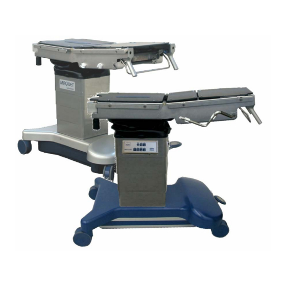
- Page 1 111801 / 02 / 03 Betaclassic / Alphaclassic Maintenance and Mobile O.R. table Repair Instructions 1118.0XGB_06 MAQUET GmbH + Co. KG · Postfach 2162 · D-76411 Rastatt Telefon (07222) 932-0 · 06.2005...
- Page 2 Wartungs- und Reparaturanleitung Alphaclassic / Betaclassic 1118 Maintenance and Repair Instruction 1118.0XGB_ 06 Page: 1...
-
Page 3: Table Of Contents
Wartungs- und Reparaturanleitung Alphaclassic / Betaclassic 1118 Maintenance and Repair Instruction Contents Page: General Design and functional description Summary of functional parts Transformer, charging unit (1118.02 / 03) Batteries (1118.02 /03) Controller unit A1 and IR-receiver board A4 (1118.03) Corded hand control (1118.03) Override board A2 (1118.03) IR-remote control (1118.03) Measurements and tests - electrical, electronic (1118.02) -
Page 4: General
Maintenance and Repair Instruction General MAQUET products are to be serviced annually (assuming between 200 and 300 hours in service each year). Damaged and/or defective components can be replaced by following the instructions given in this manual. Special tools and equipment will be required for certain repairs. - Page 5 Wartungs- und Reparaturanleitung Alphaclassic / Betaclassic 1118 Maintenance and Repair Instruction 1118.0XGB_ 06 Page: 4...
-
Page 6: Design And Functional Description
Wartungs- und Reparaturanleitung Alphaclassic / Betaclassic 1118 Maintenance and Repair Instruction 1. Design and functional description The main components: - Transformer (1118.02/03) - Charging unit, Batteries (1118.02/03) - DC motor (1118.02/03) - Hydraulic pump (1118.02/03) - Pedal pump - 6/3 directional valve with selector calotte - Lowering valve - Hydraulic pressure lines, hydraulic cylinders - Lowering valve (check valve) -
Page 7: Controller Unit A1 And Ir-Receiver Board A4 (1118.03)
Wartungs- und Reparaturanleitung Alphaclassic / Betaclassic 1118 Maintenance and Repair Instruction Controller unit A1 and IR- receiver board A4 (type 1118.03 only) The controller unit A1 is located underneath the black bellows and is covered by a metal protection plate. The IR receiver board is plugged onto the controller unit A4 as an additional board. - Page 8 Wartungs- und Reparaturanleitung Alphaclassic / Betaclassic 1118 Maintenance and Repair Instruction Charger unit (0970.2083) 1118 1118.0XGB_ 06 Page: 7...
-
Page 9: Batteries (1118.02 /03)
Wartungs- und Reparaturanleitung Alphaclassic / Betaclassic 1118 Maintenance and Repair Instruction 2. Measurements and tests - electrical, electronic Measurements at the primary part (1) - transformer T1 Voltage as per the selector position and the actual mains voltage. Measurements at the primary part (2) - transformer T1 2 x 14 ... - Page 10 Wartungs- und Reparaturanleitung Alphaclassic / Betaclassic 1118 Maintenance and Repair Instruction 90 bar 1118.01/02 100 bar 1118.03 1118.01 / 02 1118.03 1118.0XGB_ 06 Page: 9...
-
Page 11: Measurements And Tests - Hydraulic
Wartungs- und Reparaturanleitung Alphaclassic / Betaclassic 1118 Maintenance and Repair Instruction 3. Measurements and tests - hydraulic Please note: Before a hydraulic line is opened the concerned cylinder must be free from mechanical load i.e. it must be prevented from sinking down. Move the piston rod to a position in which it is free from load. In most cases this will be the lowermost position of the table movement. - Page 12 Wartungs- und Reparaturanleitung Alphaclassic / Betaclassic 1118 Maintenance and Repair Instruction 1118.01/02 1118.03 1118.0XGB_ 06 Page: 11...
- Page 13 Wartungs- und Reparaturanleitung Alphaclassic / Betaclassic 1118 Maintenance and Repair Instruction Oil tightness of the double check valve (3) or lowering valve (5) To test oil tightness of the valve (3) or (5) the function in question must be free from mechanical load and supported to prevent it from moving.
- Page 14 Wartungs- und Reparaturanleitung Alphaclassic / Betaclassic 1118 Maintenance and Repair Instruction 1118.0XGB_ 06 Page: 13...
-
Page 15: Double Check Valve (1118.03)
Wartungs- und Reparaturanleitung Alphaclassic / Betaclassic 1118 Maintenance and Repair Instruction Check valve (type 1118.03) To test oil tightness of the valve (3) the function in question must be free from mechanical load and supported to prevent it from moving. To test oil tightness of the valves (3) the segment in question must be free from mechanical load and secured. -
Page 16: Corded Hand Control (1118.03)
Wartungs- und Reparaturanleitung Alphaclassic / Betaclassic 1118 Maintenance and Repair Instruction Corded hand control (1118.03 only) Functions of the hand control can be simulated by means of the override keypad A2. If functions can be moved by the override panel but not by hand control, either the hand control or the controller unit A1 is defective. -
Page 17: Identification Of Faults - What To Do If
Wartungs- und Reparaturanleitung Alphaclassic / Betaclassic 1118 Maintenance and Repair Instruction 4. Troubleshooting – what to do if... In the course of troubleshooting please always proceed in the correct order of testing parts to ensure that the defective part can be localised and identified. Random testing of different components will hardly be crowned with success. - Page 18 Wartungs- und Reparaturanleitung Alphaclassic / Betaclassic 1118 Maintenance and Repair Instruction 1118.0XGB_ 06 Page: 17...
-
Page 19: Repair Work / Instructions For Replacement Of Components
Wartungs- und Reparaturanleitung Alphaclassic / Betaclassic 1118 Maintenance and Repair Instruction 5. Repairwork, Replacement of hydraulic and mechanical components Replacement of the column casings and the bellows Bellows Lock the O.R. table on the floor. Remove all screws (4) of the seat plate (3). Remove the seat plate (3). - Page 20 Wartungs- und Reparaturanleitung Alphaclassic / Betaclassic 1118 Maintenance and Repair Instruction 1118.0XGB_ 06 Page: 19...
-
Page 21: Guiding
Wartungs- und Reparaturanleitung Alphaclassic / Betaclassic 1118 Maintenance and Repair Instruction Guiding Separate the table top from the column: Adjust the column to its uppermost position. Remove the bellows. Lower the column casing. Adjust the tilting movement fully to the left hand side. Secure the table top to prevent it from lateral moving. - Page 22 Wartungs- und Reparaturanleitung Alphaclassic / Betaclassic 1118 Maintenance and Repair Instruction 1118.0XGB_ 06 Page: 21...
-
Page 23: Castors With Locking Lever
Wartungs- und Reparaturanleitung Alphaclassic / Betaclassic 1118 Maintenance and Repair Instruction Castors with brake lever Fixed castors: Move the table top to its uppermost position and lock it on the floor. Loosen the base casing, move it upward and secure it to the table top. Remove 2 screws (1). - Page 24 Wartungs- und Reparaturanleitung Alphaclassic / Betaclassic 1118 Maintenance and Repair Instruction 1118.0XGB_ 06 Page: 23...
-
Page 25: Pedal Pump (1118.01 / 02)
Wartungs- und Reparaturanleitung Alphaclassic / Betaclassic 1118 Maintenance and Repair Instruction Pedal actuated pump This pump is to be replaced along with the pump lever (one assembly group) Loosen the upper base casing, lift it up and secure it to the table top. Adjust the column to the uppermost position. - Page 26 Wartungs- und Reparaturanleitung Alphaclassic / Betaclassic 1118 Maintenance and Repair Instruction 1118.0XGB_ 06 Page: 25...
-
Page 27: 6/3 Directional Valve With Switch Tray (1118.01 / 02)
Wartungs- und Reparaturanleitung Alphaclassic / Betaclassic 1118 Maintenance and Repair Instruction 6/3 directional valve with switch tray Please note: If the 6/3 directional valve has to be replaced ensure that you have also a new switch tray 0799.2212) at hand – it may be destroyed during replacement work. Loosen the base casing, lift it and secure it to the table top. - Page 28 Wartungs- und Reparaturanleitung Alphaclassic / Betaclassic 1118 Maintenance and Repair Instruction 1118.0XGB_ 06 Page: 27...
-
Page 29: Lowering Valve (1118.01 / 02)
Wartungs- und Reparaturanleitung Alphaclassic / Betaclassic 1118 Maintenance and Repair Instruction Lowering valve (Model 1118.01/02) Loosen the base casing, lift it up and secure it to the table top. Adjust the column to the uppermost position. Tilt the O.R. table and lay it down on the floor. Remove the lower base casing. - Page 30 Wartungs- und Reparaturanleitung Alphaclassic / Betaclassic 1118 Maintenance and Repair Instruction 1118.01 / 02 1118.03 height tilt trendelenburg 1118.0XGB_ 06 Page: 29...
-
Page 31: Lowering Valve (1118.01 / 02)
Wartungs- und Reparaturanleitung Alphaclassic / Betaclassic 1118 Maintenance and Repair Instruction Replacement of double check valves (types 1118.01 and .02 only) Remove the column casing (see 5.1) Support the segment in question (cylinder) of the valve to be replaced to prevent it from moving during service work Disconnect the hydraulic lines (1) of the valve (2) and stopper them. - Page 32 Wartungs- und Reparaturanleitung Alphaclassic / Betaclassic 1118 Maintenance and Repair Instruction 1118.0XGB_ 06 Page: 31...
-
Page 33: Hydraulic Cylinders (Height, Tilting, Trendelenburg)
Wartungs- und Reparaturanleitung Alphaclassic / Betaclassic 1118 Maintenance and Repair Instruction Replacement of cylinders Height cylinder (1118.01 and .02 only) Remove the seat plate. Loosen the bellows. Adjust the column of the O.R. table to lowermost position. Remove the fixation brackets (5). Tilt the O.R. - Page 34 Wartungs- und Reparaturanleitung Alphaclassic / Betaclassic 1118 Maintenance and Repair Instruction 1118.02 1118.02 1118.03 1118.0XGB_ 06 Page: 33...
-
Page 35: Hydraulic Power Unit (1118.02 / 03)
Wartungs- und Reparaturanleitung Alphaclassic / Betaclassic 1118 Maintenance and Repair Instruction Hydraulic unit, motor (1118.02, 1118.03) Hydraulic unit: Disconnect the O.R. table from the mains supply. Loosen the base casing, lift it up and secure it to the table top. Unplug X3 from the charger board. - Page 36 Wartungs- und Reparaturanleitung Alphaclassic / Betaclassic 1118 Maintenance and Repair Instruction 5.10 1118.0XGB_ 06 Page: 35...
-
Page 37: Charging Unit, Batteries (1118.02)
Wartungs- und Reparaturanleitung Alphaclassic / Betaclassic 1118 Maintenance and Repair Instruction 5.10 Charger board, batteries (1118.02) Charger board: Disconnect the O.R. table from the mains supply. Loosen the upper base casing (3), lift it up and secure it to the table top. Remove 2 screws (1) of the cover (2), remove the cover. - Page 38 Wartungs- und Reparaturanleitung Alphaclassic / Betaclassic 1118 Maintenance and Repair Instruction 5.10 1118.0XGB_ 06 Page: 37...
-
Page 39: Charging Unit, Batteries (1118.03)
Wartungs- und Reparaturanleitung Alphaclassic / Betaclassic 1118 Maintenance and Repair Instruction Charger board, batteries (1118.03) Charger board: Disconnect the O.R. table from the mains supply. Loosen the upper base casing (1), lift it up and secure it to the table top. Remove the cover (2). - Page 40 Wartungs- und Reparaturanleitung Alphaclassic / Betaclassic 1118 Maintenance and Repair Instruction 5.11 1118.0XGB_ 06 Page: 39...
-
Page 41: Gas Spring (Back And Leg Plate)
Wartungs- und Reparaturanleitung Alphaclassic / Betaclassic 1118 Maintenance and Repair Instruction 5.11 Gas spring Gas spring of backrest Loosen the locking nut (1) . Remove the circlip (2) remove the pivot bolt (3) to the outside. Pay attention to the distance sleeves (4) and (5) . Turn the gas spring (7) to the front and unscrew it. - Page 42 Wartungs- und Reparaturanleitung Alphaclassic / Betaclassic 1118 Maintenance and Repair Instruction 5.12 1118.0XGB_ 06 Page: 41...
-
Page 43: Longitudinal Shift - Bowden Cable ( Type „J", „K")
Wartungs- und Reparaturanleitung Alphaclassic / Betaclassic 1118 Maintenance and Repair Instruction 5.12 Longitudinal movement – Bowden-cable (Variante “J”, “K”) Disassembly: Remove 3 screws (1). Remove the locking plate (3) from the strut (2). Loosen 2 grub screws (10). Pull the traction cable (4) back. Remove the spring guide (11) and the spring (9). Completely remove the bowden cable (7). - Page 44 Wartungs- und Reparaturanleitung Alphaclassic / Betaclassic 1118 Maintenance and Repair Instruction 5.13 1118.0XGB_ 06 Page: 43...
-
Page 45: Longitudinal Shift - Linear Guide ( Type „J", „K")
Wartungs- und Reparaturanleitung Alphaclassic / Betaclassic 1118 Maintenance and Repair Instruction 5.13 Longitudinal movement – linear guide ( types “J” and “K” ) Disassembly Adjust the column to the uppermost position, adjust the table top to level position. Support the table top by means of the assembly trolley. Remove the seat plate (1). - Page 46 Wartungs- und Reparaturanleitung Alphaclassic / Betaclassic 1118 Maintenance and Repair Instruction 5.14 1118.0XGB_ 06 Page: 45...
-
Page 47: Replacement Of Gear Parts (Spindle, Cog Wheels) Of Body Elevator (Type „G", „H")
Wartungs- und Reparaturanleitung Alphaclassic / Betaclassic 1118 Maintenance and Repair Instruction 5.14 Replacement of the gear parts (spindle, cog wheels) of the body elevator (types “G”, “H”) Disassembly: Adjust the table top to a horizontal position. Remove the parts in the order as follows: the fixation screws (1) of of the back plates (2). - Page 48 Wartungs- und Reparaturanleitung Alphaclassic / Betaclassic 1118 Maintenance and Repair Instruction 5.14 1118.0XGB_ 06 Page: 47...
- Page 49 Wartungs- und Reparaturanleitung Alphaclassic / Betaclassic 1118 Maintenance and Repair Instruction Disassembly: Remove the closing cap (16). Remove the spring pin (17). Hold the spindle nut (18) in place and rotate the spindle (19) in order to remove it along with the cog wheel (20).
- Page 50 Wartungs- und Reparaturanleitung Alphaclassic / Betaclassic 1118 Maintenance and Repair Instruction 5.15 1118.0XGB_ 06 Page: 49...
-
Page 51: Controller Unit A1 And Ir-Receiver Board A4 (1118.03)
Wartungs- und Reparaturanleitung Alphaclassic / Betaclassic 1118 Maintenance and Repair Instruction 5.15 Controller unit A1 and IR receiver board A4 (1118.03 only) Disconnect the O.R. table from the mains supply Loosen the fixation of the column casing and move the casing downward. Remove the cover plate (1) Disconnect all the connectors of the controller board A1 and the IR receiver board A4. - Page 52 Wartungs- und Reparaturanleitung Alphaclassic / Betaclassic 1118 Maintenance and Repair Instruction 5.16 1118.0XGB_ 06 Page: 51...
-
Page 53: Adjustment/Setting Of The "0"- Positioning Potentiometer (1118.03)
Wartungs- und Reparaturanleitung Alphaclassic / Betaclassic 1118 Maintenance and Repair Instruction 5.16 Adjustment of the “O“- positioning - potentiometers (1118.03 only) The “0”-positioning of the table top is controlled by potentiometers B3 (tilting) and B4 (trendelenburg). The supply voltage for the potentiometers is 5V – measured between the red and the black connector cables. - Page 54 MAQUET GmhH & Co. KG Geschäftsbereich Service Kehler Straße 31 76437 Rastatt/Germany National Service-Hotline 01 80/3 21 21 44 International Service-Hotline +49/7222/932-745 E-mail: info.service@maquet.de Internet: www.maquet.com Technische und konstruktive Änderungen vorbehalten. The right is reserved to make technical and design changes.
Need help?
Do you have a question about the 111801 and is the answer not in the manual?
Questions and answers