Table of Contents
Advertisement
Quick Links
Advertisement
Table of Contents

Subscribe to Our Youtube Channel
Related Manuals for Maquet Medap


Summary of Contents for Maquet Medap
- Page 1 OPERATING INSTRUCTIONS MEDAP HAND-HELD NEBULISER GA 5750.4172 EN 14...
- Page 2 Subject to technical modification! Illustrations and technical specifications may vary slightly from those in these Operating Instructions as a result of ongoing product development. V14 2016-07 GA 5750.4172 EN 14...
-
Page 3: Table Of Contents
Table of contents Table of contents Introduction .............................. 5 Foreword ..............................5 Environmental protection ..........................5 1.2.1 Packing ............................5 1.2.2 ATMOS products .......................... 5 Disposal ..............................5 How to use these operating instructions ....................5 1.4.1 General ............................5 1.4.2 Abbreviations .......................... - Page 4 Table of contents 3.4.5 Connection of O2 pressure reducing valve with flowmeter ............18 Operation ..............................19 Regular operation ............................. 19 Continuous nebulisation ........................... 20 Taking the unit out of operation ........................ 20 Malfunctions and troubleshooting ....................... 22 Malfunctions and troubleshooting......................22 Cleaning and disinfection ........................
-
Page 5: Introduction
Introduction Foreword Introduction Foreword Your facility has selected the leading-edge medical technology made by ATMOS. We sincerely appreciate the trust you have placed in us. Environmental protection 1.2.1 Packing The packing is made of materials compatible with the environment. ATMOS will dispose of the packing materials upon request. -
Page 6: Actions And Responses
Introduction Actions and responses 1.4.3.2 Actions and responses The „“ symbol identifies an action taken by the user while the „“ symbol identifies the reaction that this will induce in the system. Example: Turn on the light switch. Lamp lights up. 1.4.4 Definitions 1.4.4.1... - Page 7 Introduction Symbols used Symbols Identification Labelling in compliance with the EN 980 standard. Symbol for "Product number". Labelling in compliance with the EN 9801 standard. Symbol for "Name and address of the manufacturer as well as date of man- ufacture". Labelling in compliance with the EN 980 standard.
-
Page 8: Hand-Held Nebuliser
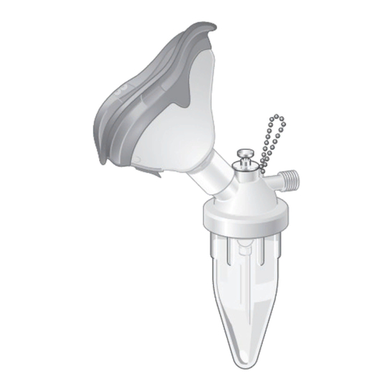
Introduction Hand-held nebuliser Hand-held nebuliser 1.5.1 Pictorial guide for hand-held nebuliser Fig. 1: Pictorial guide for hand-held nebuliser 1 Inhalation mask 9 Connection tube for compressed air or oxygen 2 Fastening chain 10 Seal 3 Nebuliser housing 11 Profile seal 4 Medicine cup 12 O-ring 5 Adapter... -
Page 9: Applicable Standards
Introduction Applicable standards When employed in a commercial or business use, this product shall be entered in the inventory. Accessories Accessories or combinations of accessories may be utilised only as and when indicated in these operating instructions. Other accessories, combinations of accessories and consumable items may be used only if they have a valid certification, are intended expressly for the particular use and will not adversely affect performance, the prescribed ambient conditions or safety requirements. -
Page 10: Incorrect Operation/Contraindications
Introduction Incorrect operation/contraindications 1.5.4.1 Incorrect operation/contraindications The hand-held nebuliser is not approved for the following purpose or under the following conditions: • for oil-based medication, • for medication generating an explosive mixture with oxygen, • for connection to respiratory systems, •... -
Page 11: Interface Description
Introduction Interface description All the components of the hand-held nebuliser can be reused following appropriate conditioning. Only devices or parts which are approved by ATMOS for combination in accordance with the accessory list or in accordance with the mounting point description may be used in conjunction with the hand-held nebuliser. -
Page 12: Principal Safety Notes
Principal safety notes General safety notes Principal safety notes General safety notes DANGER! Danger to life! The user must check the functionality and suitability of the components for the respective application and verify biocompatibility. DANGER! Incorrect use can result in fatalities! Instructions for using components made by other manufacturers are not part of these operating instructions. - Page 13 Principal safety notes General safety notes DANGER! Risk of fire! The product may ignite if the maximum operating pressure or the maximum operating temperature is exceeded. Do not exceed the maximum operating pressure or maximum operating temperature. DANGER! Health hazard! Pay attention that the product is connected to the appropriate gas type and that the screw connection is firmly seated.
-
Page 14: Ga 5750.4172 En
Principal safety notes General safety notes WARNING! Malfunction! The hand-held nebulizer may only be operated when it is vertical. The patient must be cooperative and must be able to press the hand-held nebulizer to his/her mouth and nose in vertical position. WARNING! Reasons for poor performance! Operating pressures other than 500 kPa ±... -
Page 15: Initial Operation
Initial operation Equipment inspection Initial operation Equipment inspection DANGER! Equipment inspection! Only components which are in perfect condition can ensure proper functioning of the product. The components will thus have to be carefully inspected before using the unit. WARNING! Infection hazard! Contaminated components may endanger the health of the staff and the patients. -
Page 16: Assembly And Connection Of Accessories
Initial operation Assembly and connection of accessories Assembly and connection of accessories DANGER! Danger to life! Hazard resulting from incorrect handling. Be absolutely sure to observe the operating instructions for all the products used in the configuration. WARNING! Configuration of accessory! The design of the accessory is crucial for the proper function of the tapping unit. -
Page 17: Connection Of The S Flow Flowmeter
Initial operation Connection of the S FLOW flowmeter 3.4.2 Connection of the S FLOW flowmeter Ensure that the coupling ring of the connection tube is fitted with flat gaskets. Ensure that the adapter contains a flat gasket. Screw adapter (1) directly to the flowmeter output (2) and tighten fingertight until stop. -
Page 18: Connection Of Fina Fine Regulating Valve
Initial operation Connection of FINA fine regulating valve 3.4.4 Connection of FINA fine regulating valve Ensure that the coupling ring of the connection tube is fitted with flat gaskets. Tighten the connection tube (1) with the larger coupling ring (2) fingertight onto the connector (3) of the fine regulating valve. -
Page 19: Operation
Operation Regular operation Operation The FINA fine regulating valve is used to describe the operation of the unit. WARNING! Risk of injury! The product may only be used in combination with a regulator unit. NOTE A fastening chain is attached to the hand-held nebulizer to suspend the hand-held nebulizer to a rail bracket. -
Page 20: Continuous Nebulisation
Operation Continuous nebulisation Continuous nebulisation NOTE An open knurled head screw allows continuous nebulisation. Turn knurled head screw (1) upward. Hand-held nebulizer is set to continuous nebulisation. Fig. 10: Continuous nebulisation Taking the unit out of operation The FINA fine regulating valve is used to describe how to take the unit out of operation. Taking the unit out of regular operation ... - Page 21 Operation Taking the unit out of operation Taking the unit out of continuous operation Close the knurled head screw (1) after completing inhalation. If the inhalation is interrupted for a longer time, close the gas supply on the regulating unit (2) of the fine regulating valve.
-
Page 22: Malfunctions And Troubleshooting
Malfunctions and troubleshooting Malfunctions and troubleshooting Malfunctions and troubleshooting Malfunctions and troubleshooting Defect Source of malfunction Corrective actions None or reduced Closed knurled head screw Release or open knurled head screw nebulisation Nozzle, suction sleeve or piece Clean contaminated parts of tube is contaminated Defective connection tube or Check, or, if necessary, replace... -
Page 23: Cleaning And Disinfection
Cleaning and disinfection General Cleaning and disinfection General The product must be cleaned as well as wipe disinfected after every use. DANGER! Risk due to incorrect use of detergents and disinfectants! It is strictly advised to observe the manufacturer instructions regarding how to use the detergents and disinfectants as well as the valid hospital hygiene rules. -
Page 24: Disassembly
Cleaning and disinfection Disassembly Disassembly CAUTION! Improper cleaning can cause property damage! Disassemble inhalation mask, nebulizer housing, profile gasket and medicine cup for reconditioning. Separate nozzle, suction sleeve and piece of tube to avoid that the parts stick together during reconditioning. Disassembly ... -
Page 25: Cleaning Procedure
Cleaning and disinfection Cleaning procedure CAUTION! Improper cleaning can cause property damage! Do not spray cleaning agent directly into the joints or gaps and never use a high- pressure cleaning unit! 6.3.2 Cleaning procedure Use the correct dose of multi-purpose detergent with water for the degree of surface contamination and in accordance with the instructions of the detergent manufacturer. -
Page 26: Disinfection
Cleaning and disinfection Disinfection Disinfection 6.4.1 General CAUTION! Material damage due to excessive exposure times! Exceeding the specified exposure time of the disinfectant may damage the surfaces. Remove disinfectant residues with a cloth dipped in clean water. Then dry the product with a dry, lint free cloth. -
Page 27: Disinfection Procedure
Cleaning and disinfection Disinfection procedure * Antifect (Registered trademark of Schülke und Mayr GmbH) ® * Lysetol (Registered trademark of Schülke und Mayr GmbH) ® * Gigasept (Registered trademark of Schülke und Mayr GmbH) ® * Sekusept (Registered trademark of Ecolab GmbH & Co OHG) ®... - Page 28 Cleaning and disinfection Special safety notes DANGER! Material changes! Autoclaving with heated steam accelerates the natural aging of plastics. The function of the equipment components may be impaired by material changes. Check the function of the equipment components after each treatment. DANGER! Health hazard! The product is used to administer medication.
-
Page 29: Maintenance
Maintenance Visual and functional inspections Maintenance DANGER! Health hazard! The product is used in the treatment of patients. The product or some of its components may be contaminated. Clean and disinfect the product before maintenance and repair. Repair work may be performed by personnel authorized by ATMOS. - Page 30 Maintenance Repairs These authorised service technicians can obtain descriptions, circuit diagrams, spare parts lists and testing schedules for system components that ATMOS has deemed to be repairable in the field. If defects are detected the product may not be used any longer. Make a note of the deficiencies and the REF number on the data plate and notify the responsible ATMOS Service.
-
Page 31: Technical Specifications
Technical specifications General Technical specifications NOTE Technical specifications refer to an operating pressure of 500 kPa. The technical specifications may be different if other operating pressures are used. General Classification as per Annex IX of the 93/42/EEC Class IIb Directive Operating principle Venturi system Max. -
Page 32: Particle Size Distribution
Technical specifications Particle size distribution Particle size distribution Particle size distribution of the aerosol spray (share in %; particle size in μm). The dark bar indicates the mean value. Fig. 15: Particle size distribution depends on the recorded particle size class GA 5750.4172 EN 14... -
Page 33: Cumulative Frequency
Technical specifications Cumulative frequency Cumulative frequency Diagram of cumulative frequency of the average particle size distribution of the aerosol spray (share in %; particle size in μm). The darker line indicates the mean value. Fig. 16: Diagram of the cumulative size distribution of the results GA 5750.4172 EN 14... -
Page 34: Delivery Program
Delivery program Accessories Delivery program Accessories The following accessories are not part of the scope of delivery and must be ordered separately: FINA FLOW O 15 See price information FINA DFLOW O 15 See price information FINA FLOW A 15 See price information S FLOW O 15... - Page 35 Notes...
- Page 36 Manufacturer: Distributor: MAQUET GmbH ATMOS Kehler Str. 31 MedizinTechnik GmbH & Co. KG 76437 Rastatt Ludwig-Kegel-Str. 16 Baden-Wuerttemberg 79853 Lenzkirch GERMANY GERMANY Telephone: +49 7222 932-0 Phone: +49 7653 689-0 www.maquet.com www.atmosmed.com...
Need help?
Do you have a question about the Medap and is the answer not in the manual?
Questions and answers