
Related Manuals for Maquet 1133.12B1


Summary of Contents for Maquet 1133.12B1
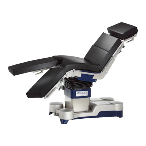
- Page 1 ALPHAMAXX 1133.12B1/B3/ F1/F3 Operating instructions Universal operating table GA113312EN02...
-
Page 2: Pictorial Guide
1133.12B1/B3/F1/F3 Pictorial guide Head plate (e.g. 1130.64) Fastening screws for head plate Locking lever for extension segment 1131.31XX Locking lever for extension segment 1131.31XX (optional) Mounting point for back plates Lower back plate Bellows Leg plates 1133.53XX (optional) Locking lever for leg plate abduction... -
Page 3: Table Of Contents
1133.12B1/B3/F1/F3 Table of contents Pictorial guide ............................. 2 Important safety notes ........................5 Important information ........................7 Important information on these operating instructions: .............. 7 Intended use of an operating table .................... 7 Intended purpose: ........................7 Fundamental safety aspects ....................7 III. - Page 4 1133.12B1/B3/F1/F3 VI. Care and maintenance ......................44 Cleaning ..........................44 Disinfection ..........................44 Maintenance .......................... 45 Malfunctions .......................... 45 Environmental protection ......................46 VII. Technical specifications ......................47 Operating table adjustments ....................47 Electrical specifications ......................47 VIII. List of accessories ........................48 Accessories for head-side mounting point: ................
-
Page 5: Important Safety Notes
Hazard of damage! Avoid any collisions between the accessories and the operating table during adjustment procedures! Consult MAQUET prior to using accessories produced by other manufacturers if they affect the longitudinal geometry of the table top. There is no explosion protection while recharging the batteries or when the operating table is on mains power. - Page 6 I. Important safety notes 1133.12B1/B3/F1/F3 Injury hazard! Before aligning the leg plates horizontally, check the patient’s position carfully, particularly when using knee crutches. Hazard of pinching and crushing! Do not touch the side rails in the area of the joints when adjusting the table top.
-
Page 7: Important Information
Intended use of an operating table The operating tables distributed by MAQUET are to be used exclusively in the field of human medicine. Before the equipment is used, all users must be instructed in its proper use. This familiarization session is confirmed in an acceptance log. -
Page 8: General Description
III. General description 1133.12B1/B3/F1/F3 III. General description General features In princliple, the operating table 1133.12 ALPHAMAXX is suitable for the following surgical procedures: • in the thorax and abdominal areas • in the head area • in gynaecology • in urology •... -
Page 9: Control Of Functions
III. General description 1133.12B1/B3/F1/F3 Control of functions The electrohydraulic functions of the operating table can be activated using one of the following control elements: • Corded hand control (see 2.1) • Override system = emergency operation(see 2.2) or optionally via: •... -
Page 10: Corded Hand Control
III. General description 1133.12B1/B3/F1/F3 2.1 Corded hand control The corded hand control is connected to the operating table at one of the two sockets (14) (for simultaneous connection of corded hand control and foot switch) on the override panel (13). The electric motor-powered ad-... -
Page 11: Override System = Emergency Operation
III. General description 1133.12B1/B3/F1/F3 0-position Resets the lateral tilt, Trendelenburg/reverse Trendelenburg, back plate and leg plate ad- justments to the horizontal position. If the function button z is pressed, the operating table top will first reset the adjustments in the following order: lateral tilt, Trendelenburg/re- verse Trendelenburg, back plate. - Page 12 III. General description 1133.12B1/B3/F1/F3 The functions of the override control panel are shown in the following: A) LED-Status indicators of the operating table Note: The status indicators are only active when the corded hand control or the IR remote control is switched on.
-
Page 13: Ir Remote Control (Optional)
III. General description 1133.12B1/B3/F1/F3 DOWN Slope leg plate downward LOCK Operating table immobilized UNLOCK Operating table on its castors, can be dis- placed 2.3 IR remote control (optional) The operating table can be equipped with an IR remote control, as desired. -
Page 14: Ir System Code
III. General description 1133.12B1/B3/F1/F3 2.3.1 IR system code Every IR remote control is unequivocally assigned to an operating table by way of the electronic encoding. The operating table has the same system code as the as- sociated IR remote control. -
Page 15: Charging Station
III. General description 1133.12B1/B3/F1/F3 2.3.2 Charging station Recharging the IR remote control: • Connect the mobile charging station to the mains. The green LED in the charging station indicates whether the required supply voltage is available or not. • Place the IR remote control in the charging station as follows: –... -
Page 16: Control Via Foot Switch 1009.81Dx (Optional)
Observe the operating instructions for the foot switch. 2.6 „Neurolock“ function If requested, the MAQUET service personnel can set the „Neurolock“ function at the operating table. This function avoids adjustments of the table position due to unintentional actuation of the buttons on the hand control. -
Page 17: General Features
III. General description 1133.12B1/B3/F1/F3 Table top 3.1 General features The table top 1133.12 has been designed to meet the requirements of various surgical disciplines. Selecting from a variety of modules lets you adapt the geometry of the table top to accommodate the individual patient height. -
Page 18: Mechanical Adjustments
III. General description 1133.12B1/B3/F1/F3 3.2 Mechanical adjustments 3.2.1 Mount / remove the head plate Note Use and handling are described in detail in the op- erating instructions for this product. Note The head plate adapter 1130.81A0 is required to mount head plates at the back plate mounting point. - Page 19 1133.12B1/B3/F1/F3 III. General description ⌧ Tighten the locking screws (E). ⌧ Pull on either side of the seat plate extension to ensure that it is properly secured. Fig.III-16: Mount and secure the head plate Remove the head plate ⌧ Loosen the locking screws (E).
- Page 20 III. General description 1133.12B1/B3/F1/F3 3.2.1.2 Mount / remove the joint adapters 1131.82A0 Note The joint adapter consists of a left and a right part. Please observe the markings L and R. If the joint adapters are mixed up, they cannot be used since the eccentric levers will point to the mid- dle of the table top.
- Page 21 III. General description 1133.12B1/B3/F1/F3 ⌧ Pull on the adapter to ensure that it is properly secured. Fig.III-20: Check to ensure proper attachment Remove the joint adapters ⌧ Swivel the joint adapters (L) and (R) upward in the direction of the arrows, up to the stop.
- Page 22 III. General description 1133.12B1/B3/F1/F3 3.2.1.3 Change out accessories at the joint adapter 1131.82A0 ⌧ If a back plate (A) is already mounted: Hold the back plate. ⌧ On either side: Press on the safety push-button (B) and open the eccentric lever (C).
-
Page 23: Extension Segment 1131.31B0/F0
III. General description 1133.12B1/B3/F1/F3 3.2.2 Extension segment 1131.31B0/F0 The table top is extended to position taller patients or to optimize the patient position. Mount the extension segment ⌧ If necessary, remove the head plate ⌧ Insert the pins of the extension segment (A) in the mounting sockets (B) at the front of the table top, up to the stop. -
Page 24: Collision Protection At The Leg Plate Mounting Point
III. General description 1133.12B1/B3/F1/F3 3.3 Collision protection at the leg plate mounting point The table top is fitted with an accessory recognition feature at the leg plate mounting point. When using encoded leg plate accessories, this feature recognizes the accessories and avoids collision with the operating table or the floor during leg plate adjustment. -
Page 25: Seat Plate Extensions
III. General description 1133.12B1/B3/F1/F3 3.3.1 Seat plate extensions The seat plate extension is suitable for use during pro- cedures in gynaecology and urology. Seat plate extension 1133.55BC • To mount or remove the seat plate extension, actu- ate the release lever (A) and insert the seat plate extension in the mounting sockets up to the stop or remove it. -
Page 26: Leg Plates
III. General description 1133.12B1/B3/F1/F3 3.3.2 Leg plates Split leg plate 1133.53BC • To mount the split leg plates, press the push-button (10) and insert the leg plate pins in the mounting sockets, up to the stop (Abb. III-30). • The leg plate is locked as soon as the push-button is released (10) (Fig.III-31). -
Page 27: Accessories
Accessories which are mounted on the side rails of the operating table provided for this purpose should also be drawn exclusively from the MAQUET line of accesso- ries. When developing MAQUET accessories, close attention is paid to careful harmonization with the MAQUET operating tables. -
Page 28: Autodrive In The Base
III. General description 1133.12B1/B3/F1/F3 Autodrive in the base The operating table version 1133.12B3/F3 is equipped with an autodrive in the base. The operating table will start moving slowly and will slow down softly after re- leasing the function button (i or k). -
Page 29: Use Of The Operating Table
IV. Use of the operating table 1133.12B1/B3/F1/F3 IV. Use of the operating table General The operating table’s electrical conductivity has to be checked once a year! This check should be performed only by trained servicing person- nel. Note: Connect the operating table to the potential equali- zation system in the OR during the surgical proce- dure (see DIN VDE 0100 standard, Part 1). -
Page 30: Operation On Mains Power
IV. Use of the operating table 1133.12B1/B3/F1/F3 Note: We recommend to recharge the batteries overnight, but at least every 2 days, even if „low charge level“ of the batteries has not been indicated yet. Regular recharging of the batteries will ensure suffi- cient battery power for the daily OR programme. -
Page 31: Patient Positioning
1133.12B1/B3/F1/F3 V. Patient positioning V. Patient positioning General The 1133.12 modular operating table offers the possibil- ity to use various modules as the back plate, thus pro- viding advantages for adaptation of the patient position to different surgical disciplines. Note: The NORMAL patient orientation is preferable to the REVERSE patient orientation. - Page 32 V. Patient positioning 1133.12B1/B3/F1/F3 Injury hazard! If the operating table is not wide enough to en- able an ergonomic patient position, then the pa- tient may be injured. The table width extenders (1001.75A0 / 76A0) may be mounted on the side rails of the operat- ing table to enable ergonomic patient position- ing.
-
Page 33: Positioning A Patient Weighing Between 225 Kg And 450 Kg (500 Lb - 1000 Lb)
1133.12B1/B3/F1/F3 V. Patient positioning Positioning a patient weighing between 225 kg and 450 kg (500 lb - 1000 lb) 2.1 Approved accessories Injury hazard! The accessories which are mounted may not exceed the maximum length as specified in the sketch below. -
Page 34: Positioning A Patient Weighing Between 135 Kg And 225 Kg (300 Lb - 500 Lb)
V. Patient positioning 1133.12B1/B3/F1/F3 Fig. V-3: NORMAL patient orientation 450 kg (1000 lb) max. patient weight LOCK Positioning a patient weighing between 135 kg and 225 kg (300 lb - 500 lb) 3.1 Approved accessories Injury hazard! The accessories which are mounted may not exceed the maximum length as specified in the following sketch. -
Page 35: Normal Patient Orientation / Operating Table Not Immobilized (Unlock)
1133.12B1/B3/F1/F3 V. Patient positioning 3.2.1 NORMAL patient orientation / operating table not immobilized (UNLOCK) Fig. V-4: NORMAL patient orientation 225 kg (500 lb) max. patient weight UNLOCK GA113312EN02... -
Page 36: Reverse Patient Orientation / Operating Table Not Immobilized (Unlock)
V. Patient positioning 1133.12B1/B3/F1/F3 3.2.2 REVERSE patient orientation / operating table not immobilized (UNLOCK) Fig. V-5: REVERSE patient orientation 225 kg (500 lb) max. patient weight UNLOCK GA113312EN02... -
Page 37: Operating Table Immobilized (Lock)
1133.12B1/B3/F1/F3 V. Patient positioning 3.3 Operating table immobilized (LOCK) 3.3.1 NORMAL patient orientation / operating table immobilized (LOCK) Fig. V-6: NORMAL patient orientation 225 kg (500 lb) max. patient weight LOCK GA113312EN02... -
Page 38: Reverse Patient Orientation / Operating Table Immobilized (Lock)
V. Patient positioning 1133.12B1/B3/F1/F3 3.3.2 REVERSE patient orientation / operating table immobilized (LOCK) Fig. V-7: REVERSE patient orientation 225 kg (500 lb) max. patient weight LOCK GA113312EN02... -
Page 39: Positioning A Patient Weighing Up To 135 Kg (300 Lb)
V. Patient positioning 1133.12B1/B3/F1/F3 Positioning a patient weighing up to 135 kg (300 lb) 4.1 Approved accessories Injury hazard! The accessories which are mounted may not exceed the maximum length as specified in the sketch. For further accessories, please refer to the accessories list in chapter VIII. -
Page 40: Normal Patient Orientation / Operating Table Not Immobilized (Unlock)
V. Patient positioning 1133.12B1/B3/F1/F3 4.2.2 NORMAL patient orientation / operating table not immobilized (UNLOCK) Fig. V-9: NORMAL patient orientation 135 kg (300 lb) max. patient weight UNLOCK GA113312EN02... -
Page 41: Reverse Patient Orientation / Operating Table Not Immobilized (Unlock)
V. Patient positioning 1133.12B1/B3/F1/F3 4.2.3 REVERSE patient orientation / operating table not immobilized (UNLOCK) Fig. V-10: REVERSE patient orientation 135 kg (300 lb) max. patient weight UNLOCK GA113312EN02... -
Page 42: Operating Table Immobilized (Lock)
V. Patient positioning 1133.12B1/B3/F1/F3 4.3 Operating table immobilized (LOCK) 4.3.1 NORMAL patient orientation / operating table immobilized (LOCK) Fig. V-11: NORMAL patient orientation 135 kg (300 lb) max. patient weight LOCK GA113312EN02... -
Page 43: Reverse Patient Orientation / Operating Table Immobilized (Lock)
1133.12B1/B3/F1/F3 V. Patient positioning 4.2.2 REVERSE patient orientation / operating table immobilized (LOCK) Fig. V-12: REVERSE patient orientation 135 kg (300 lb) max. patient weight LOCK GA113312EN02... -
Page 44: Care And Maintenance
VI. Care and maintenance 1133.12B1/B3/F1/F3 VI. Care and maintenance Cover the operating table with surgical drapes when not in use. Cleaning Use a slightly alkaline general detergent (soap suds) containing tensides and phosphates as the active clean- ing agents to clean the operating table and the acces- sories. -
Page 45: Maintenance
UNLOCk function must not be actu- ated, otherwise the base will be lowered and cannot be mobilized again. If there is a malfunction, please inform the local MAQUET representative or the factory. Please give an accurate description of the symptoms and quote the serial number to facilitate our response and make it possible to rectify the problem more quickly. -
Page 46: Environmental Protection
VI. Care and maintenance 1133.12B1/B3/F1/F3 Environmental protection Packaging materials: The packaging used for MAQUET products is made of materials compatible with the environment. They are made of untreated wood, cardboard, recyclable plas- tics or other reusable materials. MAQUET will dispose of the packaging materials upon request. -
Page 47: Technical Specifications
1133.12B1/B3/F1/F3 VII. Technical specifications VII. Technical specifications Operating table adjustments Length without accessories: 866 mm (34.1 in.) Length incl. accessories 1130.67xx / 1131.31xx / 1133.53xx: 2090 mm (82.3 in.) Width: 530 mm (20.9 in.) Width across side rails: max. 580 mm (22.8 in.) -
Page 48: List Of Accessories
VIII. List of accessories 1133.12B1/B3/F1/F3 VIII. List of accessories Fig. VIII-1: Accessories for patients weighing up to 450 kg (1000 lb). For further approved accessories, please refer to the accessories list in chapter VIII. GA113312EN02... - Page 49 VIII. List of accessories 1133.12B1/B3/F1/F3 Fig. VIII-2: Accessories for patients weighing up to 225 kg (500 lb). For further approved accessories, please refer to the accessories list in chapter VIII. GA113312EN02...
- Page 50 1133.12B1/B3/F1/F3 VIII. List of accessories Fig. VIII-3: Accessories for patients weighing up to 135 kg (300 lb). For further approved accessories, please refer to the accessories list in chapter VIII. GA113312EN02...
-
Page 51: Accessories For Head-Side Mounting Point
VIII. List of accessories 1133.12B1/B3/F1/F3 Accessories for head-side mounting point: 1.1 For patients weighing up to 450 kg (1000 lb) 1130.67X0 Head plate with gas strut assisted adjustment, washable 1.2 For patients weighing up to 225 kg (500 lb) 1130.52X0 Head plate, simple version 1130.53X0... -
Page 52: Accessories For The Back Plate Mounting Point
VIII. List of accessories 1133.12B1/B3/F1/F3 Accessories for the back plate mounting point 2.1 For patients weighing up to 450 kg (1000 lb) 1131.82A0 Joint adapter 1150.36A0 Head plate adapter 1131.31B0 Extension segment 1131.31F0 Extension segment 1130.81A0 Head plate adapter 2.2 For patients weighing up to 225 kg (500 lb) 1131.82A0... -
Page 53: Accessories For Side Rails
VIII. List of accessories 1133.12B1/B3/F1/F3 Accessories for side rails 1001.62A0 Hand operating table, Europe 9092.3214 Padding 1001.28C0 Wrist support 1001.44C0 Arm posturing device 300 mm 1001.44D0 Arm posturing device 450 mm 1001.45C0 Upper arm posturing plate 1001.4700 Leg restraint cuff 1001.56A0... -
Page 54: Special-Purpose Accessories
VIII. List of accessories 1133.12B1/B3/F1/F3 Special-purpose accessories 1000.5600 1000.5700 Head ring, PU foam 1000.5900 Gel head ring 1000.6800 Pad, segmented (for percutaneous kidney operations, spinal column) 1003.7400 PU pad for kidney operations Control units 1009.81D0 Foot switch with the following functions: height, Trendelenburg/rev. Trendelenburg, back plate 1009.81D1... -
Page 55: Spare Parts List
• IR remote control IR remote control with charging station 1133.91A0 System digits and letters 9801.6234 Cover (for transfer board 1132.65A0) 9082.1223 Control cable with two plugs for foot switch 1009.81DX 0200.4273 Use only spare parts approved by MAQUET. GA113312EN02... - Page 56 All notes and technical data in these operating instructions reflect the status at the publication date. Since we constantly strive to improve all MAQUET products, however, we reserve the right to adopt modifications at any time, without prior notice. There might therefore be minor differences between the illustrations in these operating instructions and the product’s current design.
Need help?
Do you have a question about the 1133.12B1 and is the answer not in the manual?
Questions and answers