Table of Contents
Advertisement
Quick Links
Advertisement
Chapters
Table of Contents

Related Manuals for Maquet SERVO-i V3.1


Summary of Contents for Maquet SERVO-i V3.1
- Page 1 User’s manual (US Version) VENTILATOR SYSTEM SERVO-i V3.1...
- Page 3 Contents 1 Before use ...............3 2 Ventilation ..............15 3 Patient safety............71 4 Device description ..........81 5 Set-ups and preparations........119 6 Pre-use check .............145 7 Operating your Servo-i ........157 8 Routine cleaning ..........191 9 Maintenance ............211 10 Troubleshooting..........225 11 Technical data ...........241 12 Abbreviations and definitions ......255 13 Appendix: User Interface........259 14 Index ..............273...
- Page 4 Servo… User´s manual US edition Infant Adult Universal Options Order No: 66 00 261...
-
Page 5: Table Of Contents
1. Before use Contents Brief device description ..... 4 Intended use ......4 Intended user . -
Page 6: Brief Device Description
We hope that you will be very sufficient experience in ventilator treatment. satisfied with your new system. For the latest Intended population information about it, call your local MAQUET representative. Before use, please read the The Servo-i Ventilator System can be general information below. -
Page 7: Symbols
Before use Symbols Patient Unit CE label The device complies with User Interface the requirements of the Medical Audio off Silence alarm or confirm Device Directive 93/42/EEC. alarm. CSA label The device complies Alarm off . with the Canadian standards. Audio pause Silence alarm or Class I equipment, Type B The confirm alarm. - Page 8 Before use 12V DC / Ext. bat 12V Single use external +12V DC inlet. Note: The symbol has two different labels depending on panel version. Special waste Caution: When external +12 V DC This product contains electronic is used, at least one installed and electrical components.
-
Page 9: Support Material Related To The Servo-I System
Warnings, cautions and important Support material related to This concept comprises components intended to cover the needs of a clinical user. the Servo-i system It is divided into different components according to use to facilitate accessibility of information. If you have any comments or suggestions regarding this information material, please let us know. - Page 10 Warnings, cautions and important This User´s manual The information in this User´s manual is valid for Servo-i Ventilator System 3.1 unless stated otherwise. Here you will find the information needed to use the Servo-i system safely. It is divided into five main sections: •...
-
Page 11: General Warnings
Servo-i Ventilator System. If external Declaration are met and an agreement equipment such as computers, monitors, with Maquet is signed. Disregard of these humidifiers or printers are connected, the conditions may cause deactivation of the total system must comply with IEC 60601- system functions and may result in 1-1. -
Page 12: General Cautions
• MAQUET has no responsibility for the safe operation of the equipment if service or • It is not recommended to use the Servo repair is done by a non-professional or by Evac 180 in the Nasal CPAP mode. - Page 13 Servo-i Ventilator System. • Data on pressures can be given in cmH where: • Only original parts from MAQUET must be 1 kPa ~ 10 cmH used in the system. 100 kPa = 1bar ~1atm ~1kgf/cm (kp/cm •...
-
Page 14: Context-Related Warnings
Warnings, cautions and important • Documentation for Servo-i Ventilator • If any malfunctions are detected during the System consists of: start-up procedure, please refer to Chapter, Troubleshooting (page 225). – User´s manual • If a malfunction persists, the ventilator – Brief instructions may not be connected to the patient. - Page 15 Warnings, cautions and important Nebulization • The nebulizer must not be left unattended when connected to a patient. • Servo Humidifier/HME must be • Continuously check that the buffer liquid disconnected during nebulization level is between MIN. and MAX. during otherwise the humidifier may be blocked nebulization (page 187).
- Page 16 Notes ............................................................................................................................................................................................................................................................................................................................................................................................................Servo… User´s manual US edition Infant Adult Universal Options Order No: 66 00 261...
- Page 17 2. Ventilation Contents Modes of ventilation..... . . 16 Important definitions ..... . 21 Trigger sensitivity .
-
Page 18: Modes Of Ventilation
Modes of ventilation Ventilatory management Scope - ventilatory needs The Servo-i Ventilator System is designed for safe and effective treatment. It can be set for continuous adaptation to the patient´s prevailing condition or for manually controlled operations. The servo systems for pressure, flow and timing operate in all modes of ventilation (set time in control modes and patient-related timing in support... - Page 19 Modes of ventilation Implementation Extra flow and extra breaths In flow/volume- oriented modes of ventilation, additional on-demand flow can be triggered during inspiration. Additional breaths can always be triggered between the ordinary breaths if the set trigger criteria are met. Timing In controlled ventilation modes, timing is related to preset values.
- Page 20 Modes of ventilation Basic functionality - An overview Servo… User´s manual US edition Order No: 66 00 261 Infant Adult Universal Options...
- Page 21 Modes of ventilation 1.(PRVC) Pressure Regulated Volume Control Breaths are delivered mandatorily to assure preset volumes, with a constant inspiratory pressure continuously adapting to the patient´s condition. The flow pattern is decelerating. 2. Volume Control Breaths are delivered mandatorily with a constant flow to assure preset volumes.
- Page 22 Modes of ventilation Combined modes - An overview Automode The ventilator continuously adapts to the patient's breathing capability and allows the patient to better interact with the ventilator. The ventilator automatically shifts between controlled ventilation, supported ventilation and spontaneous ventilation. Each controlled ventilation mode has a corresponding support mode.
-
Page 23: Important Definitions
Important definitions ServoS-0046_XX The graphic display of flow, pressure and Flow-Time waveform. Points and volume is visualized in wave forms. Modes of regions of interest ventilation directly affect flow, pressure and X. Inspiration time volume patterns. Y. Pause time Volume Control Z: Expiration time 7. - Page 24 Important definitions ServoS-0047_XX Pressure Control Volume-Time waveform. Points and regions of interest Pressure-Time waveform. Points X. Inspiration time and regions of interest Z.: Expiration time X. Inspiration time 8. Start of inspiration Z. Expiration time 9. End inspiration 1. Start of Inspiration 10.
-
Page 25: Trigger Sensitivity
T r i g g e r s e n s i t i v i t y rigger functionality Trigg. Flow Trigg. Pressure The ventilator continuously delivers a gas SVX-638_EN flow during expiration, which is measured in the expiratory channel. This determines the level of patient effort to trigger the ventilator to inspiration. - Page 26 Trigger sensitivity Weak patient effort Stronger patient effort Trigg. Pressure Trigg. Flow SVX-142_EN SVX-141_EN 1. At a Trigger sensitivity level below zero 1. At a Trigger sensitivity level above zero (0), the ventilator senses negative (0), the ventilator senses deviations in pressures created by the patient.
-
Page 27: Settings
Settings Inspiratory rise time Inspiratory cycle-off Insp rise time SVX-205_XX Inspiratory Cycle-off is the point at which 100 % inspiration changes to expiration in spontaneous and supported modes of ventilation. A decrease of the inspiratory flow to a preset level causes the ventilator to switch to expiration. - Page 28 Settings Breath cycle time Trigger timeout Trigger Timeout is the maximum allowed apnea time in Automode before controlled ventilation is activated. It is applicable in: Automode: < > Volume Control Volume Support < > PRVC Volume Support < > Pressure Control Pressure Support The settings are within the ranges: •...
- Page 29 Settings I:E ratio / Inspiration time Volume setting The setting of breathing parameters in Depending on the ventilator configuration the Servo-i can be configured in two different inspiratory volume can be set as: ways, based on: – Minute Volume or, •...
- Page 30 Settings Previous ventilation mode 1. Time when previous mode was inactivated. 2. Press the pad Show previous mode to recall the previous accepted ventilation mode. 3. Activate the previous used ventilation mode settings by pressing the Accept pad. Note: • The previous ventilation mode function is not available after a Pre-use check, changing of patient category, admitting a new patient, use of the same ventilation...
-
Page 31: Special Functions
Special functions Fixed keys Start breath The ventilator will initiate a new breath cycle according to the current ventilator settings. 1. Start breath 2. O breaths 3. Expiratory hold 4. Inspiratory hold can all be chosen by manually pressing the respective fixed key. - Page 32 Special functions breaths Expiratory hold Expiratory and inspiratory valves are closed This function allows 100% oxygen to be after the expiration phase is completed, for given for 1 minute. After this time the oxygen as long as the fixed key is depressed, up to a concentration will return to the pre-set value.
- Page 33 Special functions Inspiratory hold Back-up ventilation Pressure support/ Pressure control CPAP Apnea Volume support Volume control SVX-647_EN Back-up ventilation is available in all support modes (not applicable in Automode and NIV Pressure Support mode). The Back-up function switches Volume Support to Volume Control, Pressure Support and CPAP to Pressure Control.
-
Page 34: Controlled Ventilation - Prvc
Controlled ventilation - PRVC Functional description PRVC The Pressure Regulated Volume Control (PRVC) mode is a controlled breathing mode. The ventilator delivers a pre-set Tidal Servo-i Ventilator can be configured to set Volume. The pressure is automatically Tidal Volume or Minute Volume. The regulated to deliver the pre-set volume but following parameters are set: limited to 5 cmH... - Page 35 Controlled ventilation - PRVC PRVC in detail SVX-9006_XX 1. PRVC assures a set target minute ventilation to the patient. The target volume is based upon settings for Tidal Volume, frequency and inspiration time. 2. The inspiratory pressure level is constant during each breath, but automatically adapts in small increments breath-by- breath to match the patient´s lung...
- Page 36 Controlled ventilation - PRVC SVX-697_EN The first breath of a start sequence is a volume-controlled test breath with Pause time set to 10%. The measured pause pressure of this breath is then used as the pressure level for the following breath. An alarm is activated if the pressure level required to achieve the set target volume cannot be delivered due to a lower setting of...
-
Page 37: Controlled Ventilation - Volume Control
Controlled ventilation - Volume Control Functional description Volume Control The airway pressure is dependent on the Volume Controlled ventilation ensures that tidal volume, inspiration time and the the patient receives a certain pre-set Minute/ resistance and compliance of the respiratory Tidal Volume. - Page 38 Controlled ventilation - Volume Control Volume Controlled ventilation has, by tradition, delivered each breath with a constant flow and constant inspiratory and expiratory times, according to the settings. The Servo-i gives the possibility to the patient to modify both flow rate and timing. So, if a pressure drop of 3 cmH O is detected during inspiration, the ventilator cycles to...
- Page 39 Controlled ventilation - Volume Control Volume Control in detail SVX-9002_XX 1. Volume Control assures a preset tidal volume with constant flow during a preset inspiratory time at a preset frequency. 2. The inspiratory flow is constant and depends on User Interface setting. 3.
-
Page 40: Controlled Ventilation - Pressure Control
Controlled ventilation - Pressure Control Functional description Pressure Control The Pressure Controlled mode is a controlled breathing mode. The following parameters are set: The delivered volume is dependent upon the pressure above PEEP, lung compliance and 1. PC (Pressure Control level) above PEEP resistance in the patient tube system and (cmH airways. - Page 41 Controlled ventilation - Pressure Control Pressure Control in detail SVX-9003_XX 1. Pressure Control assures that the preset Active expiratory valve inspiratory pressure level is maintained constantly during the entire inspiration. Breaths are delivered according to the preset frequency, inspiration time and inspiratory pressure level resulting in a decelerating flow.
-
Page 42: Supported Ventilation - Volume Support
Supported ventilation - Volume Support Functional description Volume Support The Volume Support mode is a patient initiated breathing mode, where the patient will be given support in proportion to their inspiratory effort and the target Tidal Volume. If the patient’s activity increases the The following parameters are set: inspiratory pressure support will decrease 1. - Page 43 Supported ventilation - Volume Support SVX-657_EN The start breath is given with 10 cmH In this mode it is also important to set the support. From that breath the ventilator apnea time appropriate to the individual calculates and continuously regulates the patient situation.
- Page 44 Supported ventilation - Volume Support Volume Support in detail SVX-9005_XX 1. Volume Support assures a set target Tidal Volume upon patient effort by an adapted inspiratory pressure support. 2. The inspiratory pressure level is constant during each breath, but alters in small increments, breath-by-breath, to match the patient´s breathing ability and lung mechanical properties.
-
Page 45: Supported Ventilation - Pressure Support
Supported ventilation - Pressure Support Functional description Pressure Support Pressure Support is a patient initiated breathing mode in which the ventilator supports the patient with a set constant pressure. During Pressure Supported ventilation the The following parameters are set: patient regulates the respiratory rate and the 1. - Page 46 Supported ventilation - Pressure Support SVX-661_XX Inspiratory Cycle-off is important for the patient’s comfort and ventilator synchronization with the patient. Inspiratory Cycle-off is the point when inspiration switches to expiration. E.g. for a patient with expiratory resistance the inspiratory Cycle- off should be set to a high value to guarantee enough time for expiration.
- Page 47 Supported ventilation - Pressure Support Pressure Support in detail SVX-9004_XX 1. Pressure Support assures that a preset inspiratory pressure level is constantly maintained upon patient effort. 2. The preset pressure level is controlled by the ventilator, while the patient determines frequency and inspiration time.
-
Page 48: Spontaneous/Cpap
Spontaneous/CPAP Functional description Spontaneous breathing/CPAP The mode Continuous Positive Airway Pressure is used when the patient is breathing spontaneously. A continuous positive pressure is maintained The following parameters are set: in the airways. Properly set this may prevent 1. PS (Pressure Support level) above PEEP collapse of airways. - Page 49 Spontaneous/CPAP Spontaneous breathing/CPAP in detail – True spontaneous breathing will occur: a. In Volume Support when the target volume is maintained without support (automatically regulated by the ventilator) b. In Pressure Support when the inspiratory pressure level is set to zero c.
-
Page 50: Automode
Automode Automode Functional description SVX-602_EN Automode is a ventilator functionality where the ventilator adapts to the patient's varying breathing capacity and automatically shifts between a control mode and a support mode using a fixed combination of ventilation modes. There are three different combinations, depending on the modes installed: •... - Page 51 Automode Volume Control<->Volume Support Pressure Control<->Pressure Support In this combination of Automode - Pressure The ventilator uses the plateau pressure in Control and Pressure Support - the Direct the Volume Controlled breath as a reference Access Knob will regulate the PC above pressure for the first Volume Supported PEEP (Pressure Control level).
- Page 52 Automode Automode in detail 1. The ventilator starts in control mode and operates according to the Volume Control, PRVC or Pressure Control mode. If the patient triggers a breath, the ventilator will turn to support mode, to encourage the patient's respiratory drive.
- Page 53 Automode PRVC - Volume Support SVX-165_EN Volume Control - Volume Support SVX-222_EN Pressure Control - Pressure Support SVX-167_EN Servo… User´s manual US edition Order No: 66 00 261 Infant Adult Universal Options...
-
Page 54: Simv
SIMV Functional description SIMV SIMV is a combination mode where the The Breath cycle time is the length of the patient receives mandatory breaths mandatory breath in seconds. synchronized with his breathing efforts and For example: A SIMV rate of 6, a breath cycle according to the selected SIMV mode. - Page 55 SIMV SIMV (PRVC) + Pressure Support The following parameters are set: 1. Tidal Volume (ml)/Minute Volume (l/min) 2. SIMV rate (b/min) 3. PEEP (cmH 4. Oxygen concentration (%) 5. I:E ratio / Insp. time 6. Inspiratory rise time (%/s) 7. Breath cycle time (s) Note: The soft key Breath cycle time is not shown when an SIMV mode is selected and inspiration time is...
- Page 56 SIMV SIMV (PRVC) + Pressure Support SIMV SIMV Breath cycle Spont. period Breath cycle time time time time SVX-9027_EN SIMV - in detail 1. This combined control and pressure support/spontaneous function allows for preset mandatory breaths synchronized with the patient's breathing. 2.
- Page 57 SIMV SIMV (Volume Control) + Pressure Support The following parameters are set: 1. Tidal Volume (ml)/Minute Volume (l/min) 2. SIMV rate (b/min) 3. PEEP (cmH 4. Oxygen concentration (%) 5. I:E ratio / Insp. time 6. Pause time (%/s) 7. Inspiratory rise time (%/s) 8.
- Page 58 SIMV SIMV (Volume Control) + Pressure Support SIMV SIMV Breath cycle time Spont. period Breath cycle time time time SVX-9011_EN SIMV - in detail 1. This combined control and pressure support/spontaneous function allows for preset mandatory breaths synchronized with the patient's breathing. 2.
- Page 59 SIMV SIMV (Pressure Control) + Pressure Support The following parameters are set: 1. PC (Pressure Control level) above PEEP (cmH 2. SIMV rate (b/min) 3. PEEP (cmH 4. Oxygen concentration (%) 5. I:E ratio / Insp. time 6. Inspiratory rise time (%/s) 7.
- Page 60 SIMV SIMV (Pressure Control) + Pressure Support SIMV SIMV Breath cycle Spont. period Breath cycle time time time time SVX-9027_EN SIMV - in detail 1. This combined control and pressure support/spontaneous function allows for preset mandatory breaths synchronized with the patient's breathing. 2.
-
Page 61: Bi-Vent
Bi-Vent Bi-Vent Functional description Bi-Vent is pressure controlled breathing that In the Bi-Vent mode the ventilator uses two allows the patient the opportunity of shifting pressure levels, with the patient unrestricted spontaneous breathing. Two being able to breath spontaneously on both pressure levels are set together with the these levels. - Page 62 Bi-Vent Bi-Vent in detail SVX-184_XX This function allows for spontaneous breathing / pressure supported ventilation at two different pressure levels. These basic levels are individually set, as well as the time in seconds at each level.The ventilator always tries to synchronize with the patient´s breathing.
-
Page 63: Non Invasive Ventilation (Niv)
Non Invasive Ventilation (NIV) Non Invasive Ventilation Read more about NIV This chapter refers to when the Servo-i is Intended population page 4 used during Non Invasive Ventilation (NIV). Ventilation modes (NIV): pages 62, 63 NIV refers to ventilation, where the patient is Alarm settings: page 73 not intubated or tracheotomized. -
Page 64: Niv - Pressure Control
NIV - Pressure Control Differences from invasive Pressure Functional description control mode: Pressure Control • When the Standby key is pressed a The Pressure Controlled (NIV) mode is a waiting position dialog is shown. All controlled breathing mode. patient related alarms are turned off during 120 seconds. -
Page 65: Niv - Pressure Support
NIV - Pressure Support Differences from invasive Pressure Functional description support mode: Pressure Support • When the Standby key is pressed a Pressure Support (NIV) is a patient initiated waiting position dialog is shown. All breathing mode in which the ventilator patient related alarms are turned off during supports the patient with a set constant 120 seconds. -
Page 66: Niv - Nasal Cpap
NIV - Nasal CPAP Functional description Nasal Differences from invasive CPAP CPAP • When the Standby key is pressed a waiting position dialog is shown. All The mode Nasal Continuous Positive Airway patient related alarms are turned off during Pressure is used when the patient is 120 seconds. -
Page 67: Open Lung Tool
Open Lung Tool Open Lung Tool Clinical performance The Open Lung Tool is a tool for graphically visualizing measured and calculated values for easier interpretation of already available ventilation data. Three simultaneous graphical trends are presented with a fixed set of parameters as a function of a number of collected breaths. -
Page 68: Ventilatory Parameters, Overview
Ventilatory parameters, overview SVX-202_EN When a ventilation mode is selected, the only 9. Trigger sensitivity parameters shown are those affecting the a) Below zero: Trigger sensitivity is pressure actual mode. Below are all the mode-related dependant. The pressure below PEEP which parameters presented. - Page 69 Ventilatory parameters, overview SVX-218_EN SVX-203_EN 12. Breath cycle time (Breath cycle T) Total cycle time per mandatory breath in SIMV (inspiratory + pause + expiratory). Set in seconds. 13. SIMV rate Rate of controlled mandatory breaths (b/min). 14. Trigger timeout The maximum allowed apnea time in Automode, after which the system switches to controlled ventilation (s).
- Page 70 Ventilatory parameters, overview SVX-204_XX 15. Time high (T ) Time at P level in High High Bi-Vent (s). 16. Time PEEP (T ) Time at PEEP level in PEEP Bi-Vent (s). 17. Pressure Support above Pressure high (PS above P ) Inspiratory pressure High support level for breaths triggered during the...
- Page 71 Notes ............................................................................................................................................................................................................................................................................................................................................................................................................Servo… User´s manual US edition Order No: 66 00 261 Infant Adult Universal...
- Page 72 Notes ............................................................................................................................................................................................................................................................................................................................................................................................................Servo… User´s manual US edition Order No: 66 00 261 Infant Adult Universal...
- Page 73 3. Patient safety Contents Alarms- General ......72 High priority alarms ..... . . 72 Medium priority alarms .
-
Page 74: Alarms- General
Alarms- General Several measures have been taken to design Alarm output connection this system for safe treatment and use. option The alarms are based on three priority levels; High, Medium and Low. An Alarm output connection option makes it possible to connect the ventilator to an High priority alarms external alarm signal system. -
Page 75: The Alarm Profile Window
The alarm profile window Alarm profile window Non Invasive Ventilation SVX-9016_XX 1. Press the Alarm profile key 1. Press the Alarm profile key to show the applicable alarms for Non Invasive Shows all applicable alarms and settings for both lower and upper limits. Also used for Ventilation (NIV). -
Page 76: The Alarm Window
The alarm window Current alarms window This window can be displayed if more than one alarm is active. 1. Press the bell (s) in the alarm message pad. 2. All alarms are shown in a window. This is dynamic and will be updated if more alarms occur while the window is open. -
Page 77: Alarms - Visual / Audible
Alarms - Visual / audible Visual Audible An active alarm is indicated by a distinct, but soft alarm signal. The sound level can be adjusted, e.g. lowered during the night time. (Set sound level is indicated in the Alarm profile window.) Technical errors may also be indicated by a signal similar to that a medium priority alarm, generated by a sounding device in the... -
Page 78: Audio Off (Silence / Pre-Silence Of Alarm)
Audio off (Silence / Pre-silence of alarm) General Audio off (Silence of alarms) At any time while the ventilator is operating (either Invasive or Non Invasive Ventilation modes), alarms can be placed into a state of audio off (silence alarms). Non Invasive Ventilation When Non Invasive Ventilation is chosen, the following alarms can be placed into a state of... - Page 79 Audio pause (Silence / Pre-silence alarm) Audio pause/Prolong pre-silence Pre-silence alarm (Audio pause) period/Clear latched alarm SVX-5099_EN SVX-5098_EN 1. If you press the Audio pause (Silence/ 1. Press the Audio pause (Silence/Pre- Pre-silence alarm) key for more than two silence alarm) key briefly, for less than seconds: two seconds: •The active alarms are silenced (Audio...
-
Page 80: Built-In Safety Precautions
Built-in safety precautions For patient safety your Servo-i Ventilator NIV rate System also has a range of built-in safety During Pressure support (NIV) the system precautions. ensures a minimum Back-up Rate and Apnea alarm maintains the set Inspiratory pressure and PEEP level. - Page 81 Notes ............................................................................................................................................................................................................................................................................................................................................................................................................Servo… User´s manual US edition Infant Adult Universal Options Order No: 66 00 261...
- Page 82 Notes ............................................................................................................................................................................................................................................................................................................................................................................................................Servo… User´s manual US edition Infant Adult Universal Options Order No: 66 00 261...
- Page 83 4. Device description Contents The system ......82 An overview ......83 Configuration .
-
Page 84: The System
The system The ventilator All ventilatory settings are made on the User Interface panel. It can either be operated by the touch screen and the Main Rotary Dial or by using the Main Rotary Dial only. Flow and pressure are continuously measured by transducers and controlled by a feedback system in the Patient Unit. -
Page 85: An Overview
The system An overview 1. The ventilator can be delivered in three 2. The User Interface, where all settings are configurations. Your configuration is made and effects are monitored. clearly indicated on the Patient Unit, at 3. The Patient Unit, where gases are start up and in the Brief Instructions. - Page 86 The system In the system Default values give fast system start-up. An alarm output connection option User set values tailor the ventilatory makes it possible to connect the management. Signals are fed to the Patient ventilator to an external alarm signal Unit, which executes ventilation managed by system the servo control system.
-
Page 87: Configuration
Configuration System elements; overview Reference in Functionality/Configuration this manual Basic Extended Alarm output connection option pages 72, 150 Automode, pressure page 48 Automode, PRVC page 48 Automode, volume page 48 Bi-Vent page 59 Analyzer pages 104, NIV (Non Invasive Ventilation) pages 61, 160 Nasal CPAP page 64... -
Page 88: Options / Accessories
Options / Accessories General options / accessories Reference in this manual Aeroneb Professional Nebulizer System Refer to separate manual Battery module Servo-i page 108 Analyzer Servo-i pages 104, 151, 207, 238 ,247 Compressor Mini pages 115, 248 Drawer kit Servo-i page 99 Extra Expiratory cassette. -
Page 89: User Interface - General
User Interface - General An overview Mode Volume control SVX-5001_EN Read more about the User The User Interface is ergonomically designed. You can operate it via the touch Interface screen or by means of the Main Rotary Dial. Fixed keys allow immediate access. Direct Positioning: page 93 Access Knobs allow for immediate... -
Page 90: User Interface - Connections And Labels
User Interface - Connections and labels Servo… User´s manual US edition Order No: 66 00 261 Infant Adult Universal Options... - Page 91 User Interface - Connections and labels It consists of: 1. Patient category. 20. A section where measured values and set alarm limits are displayed in boxes. 2. Active mode of ventilation. You can choose which parameter values Automode On/Off. to show. 4.
-
Page 92: Touch Screen
User Interface - Functionality Touch screen Main Rotary Dial SVX-6021_XX 1. Activate the desired menu touch pad by 1. Turn the Main Rotary Dial until the pressing it. desired menu touch pad is marked with a blue frame. 2. Activate the desired parameter by pressing the touch pad (highlighted 2. -
Page 93: Fixed Keys
User Interface - Functionality Fixed keys Adjusting parameter values SVX-5089_EN There are two kinds of fixed keys: 1. Short-cut to function or screen. 2. Start special ventilatory function, which Immediate adjustment demands continuous supervision when used. 1. Turn the Direct Access Knob to the Press to activate. -
Page 94: Waveforms
User Interface - Functionality Waveforms Measured value boxes The measured value boxes show measured/ As default four waveforms are shown calculated values in numerics and the unit simultaneously (If Analyzer is being used. connected). 1. Set Lower and Upper alarm limits are 1. -
Page 95: User Interface - Positioning
User Interface - Positioning User Interface positioning The User Interface can be positioned on the Mobile Cart, a table, a shelf or a pipe. 1. Lift the User Interface straight up. 2. Place the panel on a table, shelf or on a pipe and fasten it securely by turning the handle of the locking screw. -
Page 96: User Interface - Accessories
User Interface - Accessories Knob cover The knob cover protects the Direct Access Knobs against inadvertent activation. Raise the cover to access the Direct Access Knobs. Servo… User´s manual US edition Order No: 66 00 261 Infant Adult Universal Options... - Page 97 User Interface - Accessories User Interface panel cover The User Interface panel cover protects the screen from inadvertent activation of settings and mechanical damage during transport. While attached the user can still access the vital settings. Raise the cover to access the screen.
-
Page 98: Patient Unit - Connections And Labels
Patient Unit - Connections and labels Note: Refer to chapter Before use (page 5) for more information about symbols on the Servo-i Ventilator system. Servo… User´s manual US edition Order No: 66 00 261 Infant Adult Universal Options... - Page 99 Patient Unit - Connections and labels Read more about the patient 1. Handle unit 2. Gas inlet for air 3. Gas inlet for O Positioning: pages 123, 124 Cleaning: page 191 4. Air / Luft Technical data: page 241 5. O 6.
-
Page 100: Patient Unit - Expiratory Cassette
Patient Unit - Expiratory cassette Gas flow through the Patient Unit 1. Gas inlet for O 8. The patient system´s expiratory tubing is connected to the expiratory inlet. The 2. Gas inlet for air. inlet also contains a moisture trap. 3. -
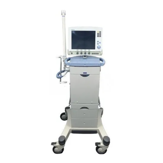
Page 101: Mobile Cart Servo-I
Mobile Cart Servo-i Mobile Cart Front and rear side Drawer kit SVX-696_XX The drawer kit with two drawers can be mounted on the Mobile Cart. SVX-008_XX SVX-571_XX The Mobile Cart Servo-i is designed for carrying the User Interface, the Patient Unit and all required optional equipment. -
Page 102: Holders
Holders Humidifier Holder Servo-i Holder SVX-568_XX SVX-037_XX The Humidifier Holder can be attached on The universal holder allows for positioning of the Mobile Cart. the Patient Unit on a bed, a stretcher or a standard rail. Servo-i Shelf base IV Pole SVX-695_XX The shelf base allows for positioning of the Patient Unit on a shelf. - Page 103 Holders Servo-i Gas trolley SVX-605_XX The Gas trolley can be attached on the Mobile Cart or to a separate wall clamp. Servo-i Gas cylinder restrainer SVX-572_XX The Gas cylinder restrainer is mounted onto the Mobile Cart. For details, please refer to the Installation instructions.
-
Page 104: Servo Ultra Nebulizer
Servo Ultra Nebulizer Note: Servo Ultra Nebulizer • For information about the stand alone The Servo Ultra Nebulizer is intended for nebulizing drugs to patients requiring Aeroneb Professional Nebulizer System, mechanical ventilation or positive pressure refer to separate manual. breathing assistance via an endotracheal •... - Page 105 Servo Ultra Nebulizer Basic principles Nebulizer Holder SVX-135_XX SVX-136_XX The holder can be used when the Servo Ultra 1. Gas from ventilator. Nebulizer is not in use or when filling with 2. Cable from ventilator. medication. 3. The ultrasonic generator produces Read more about the Servo ultrasonic waves.
-
Page 106: Co Analyzer Servo-I
The CO Analyzer processes data and • Only MAQUET airway adapter may be derives values for the following parameters: used together with the Capnostat sensor. Instantaneous CO (Capnogram) – the instantaneous value of the CO level;... - Page 107 Analyzer Servo-i Analyzer parts 1. CO Analyzer module. Basic principles 2. Connection for sensor. 3. Connector. 4. Airway adapter. 5. Capnostat sensor. 6. Reference cell. 7. Zero cell. 1. Gas flow through the airway adapter in the Capnostat sensor. 2. The sensor uses a solid state and IR based optical system with no moveable parts.
-
Page 108: Y Sensor Measuring
Y Sensor measuring automatically reactivate the Y Sensor Y Sensor measuring measuring and the dialog will disappear. The Y Sensor measuring function is based on fixed orifice, differential pressure sensor Note: technology, and allows the pressure and flow • It is recommended to place an HME or to be measured as close as possible to the patient’s airway. - Page 109 Y Sensor measuring Y Sensor measuring parts SVX-9037 1. Y Sensor module 2. Connector for sensor 3. Connector 4. Y piece 5. Y Sensor 6. Endotracheal tube Servo… User´s manual US edition Order No: 66 00 261 Infant Adult Universal Options...
-
Page 110: Battery Module
Battery module Servo-i General Important: • When delivered, the Battery modules may Battery modules are used as a power backup not be fully charged. Check the status of in the Intensive Care Unit (ICU) and during transportation. The batteries used are the batteries via the User Interface and, if “smart”... - Page 111 Battery module Servo-i Charging/Operating time The ventilator can be run for at least 30 minutes per Battery module, i.e. two Battery modules for 60 minutes. SVX-9036 The estimated remaining battery backup time, in minutes, is indicated on the User Interface – see time on Status button (when operating from batteries) at the top-right of screen.
- Page 112 Battery module Servo-i Checking battery status If, as shown in the picture, a battery needs to be replaced due to either old age or poor Pre-use check operational capacity, perform the following: A Pre-use check can be run each time the •...
- Page 113 Battery module Servo-i Battery status window The following information is displayed for each mounted Battery module: The Battery status window contains status • Slot number information on each of the Battery modules mounted in the ventilator. It also displays the •...
- Page 114 Battery module Servo-i Informative text message Text message Remedy Check battery status Mains voltage disappears. Problem with battery module. One or more Battery modules must be replaced. Open the Battery status window for information. Replace and discard battery. Activity instructions Activity instruction Remedy Expires soon...
- Page 115 Battery module Servo-i Alarms and safety The status of the Battery modules is continuously monitored by the ventilator. If the status is unsatisfactory, two types of message information can be displayed at the top of the User Interface: • Informative text message see page 230. •...
-
Page 116: Ventilation Record Card
Ventilation Record Card Ventilation record card The Ventilation record card allows for transfer of patient data or copy of screen from the ventilator system to a personal computer. Patient data can then be further processed and stored. Accessible patient data in the ventilator are the logged events, trends, recordings and Open Lung Tool data, including patient name, patient identification code, ventilator... -
Page 117: Compressor Mini
The Compressor Mini is designed to supply a ventilator with dry, filtered, compressed air. The Compressor Mini is designed to work together with all MAQUET ventilators. The Compressor Mini is equipped with a Standby function. In Standby mode, the compressor will start to deliver compressed air to the ventilator if the central compressed air supply fails. -
Page 118: System Transport And Storage
System transport and storage Before transport During transport Before transporting the ventilator with or During transportation of the ventilator with or without a patient connected, make sure that without a patient connected, make sure that the following conditions are fulfilled: the following conditions are fulfilled: •... - Page 119 System transport and storage WARNING! If the trigger sensitivity is set too high, a self-triggering (auto-triggering) condition may be reached. This condition can also be reached if there is leakage in the breathing system, e.g. if an uncuffed endotracheal tube is used. Triggering will then be initiated by the system and not by the patient.This should always be avoided by decreasing the trigger sensitivity (page 23).
- Page 120 Notes ............................................................................................................................................................................................................................................................................................................................................................................................................Servo… User´s manual US edition Order No: 66 00 261 Infant Adult Universal...
- Page 121 5. Set-ups and preparations Contents Set-ups Set-ups - Patient breathing system ..120 Preparations Preparations - Mobile Cart Servo-i ... . 123 Preparations - Holder .
-
Page 122: Set-Ups - Patient Breathing System
Set-ups - Patient breathing system 10 mm diameter SVX-017_XX 1. Servo guard, viral/bacterial filter - must 11. Servo humidifier - must be disconnected always be connected during nebulization during nebulization (page 136). 2. Nipple connector 12. Angled connector for endotracheal tube. 3. - Page 123 Set-ups - Patient breathing system 15 mm diameter 1. Servo guard, viral/bacterial filter - must 10. Angled connector for endotracheal tube. always be connected during 11. Water trap - mandatory if a heated nebulization. humidifier is used. 2. Support Arm 12.
- Page 124 Set-ups - Patient breathing system 22 mm diameter SVX-251_XX 1. Servo guard, viral/bacterial filter - must 10. Nipple connector always be connected during 11. Humidifier (Fisher &Paykel) - must not be nebulization. active during nebulization (page 127). 2. Support Arm 12.
-
Page 125: Preparations - Mobile Cart Servo-I
Preparations - Mobile Cart Servo-i Mobile Cart/positioning 1. Press the brakes to lock the wheels. Cautions: • The ventilator must only be used in an 2. Place the Patient Unit on the console upright position. plate using the guide pins. •... -
Page 126: Preparations - Holder
Preparations - Holder Holder/positioning 1. Place the Patient Unit on the holder. 2. Secure the Patient Unit with the handle. 3. Adjust the support and secure with the screws. 4. Place the holder on a Rail (or bed or stretcher). 5. -
Page 127: Preparations - Support Arm
Preparations - Support Arm Support Arm 177 1. Insert the Support Arm into the side track. 2. Tighten the screw firmly. SVX-148_XX Adjust the Support Arm, CO airway adapter and snap the breathing system into the grip. Cautions: • Use the Support Arm to relieve the patient from the weight of the tubing system. -
Page 128: Preparations - Gas Trolley
Preparations - Gas trolley Gas trolley/positioning 1. Place the gas trolley in position. 2. Hinge the gas trolley and lift it up into locking position (a "click" is heard). 3. Secure the docking with the security chains. Note: Press the brakes to lock the wheels on the Mobile Cart before positioning the gas trolley. -
Page 129: Preparations - Fisher & Paykel
• During operation the water traps must be checked regularly and if necessary emptied. Important:It is recommended only to use original tubing from MAQUET. Soft tubing may negatively effect the performance of the SVX-636_XX ventilator. Humidifier Holder 22 mm breathing system SVX-567_XX Read more about the Fisher &... -
Page 130: Preparations - Servo Ultra Nebulizer
Preparations - Servo Ultra Nebulizer Servo Ultra Nebulizer WARNINGS! • During nebulization a filter must be connected to the expiratory inlet of the • Servo Humidifier/HME must be ventilator. Always carefully monitor the disconnected during nebulization. airway pressure during nebulization. Otherwise the humidifier may be blocked. - Page 131 Preparations - Servo Ultra Nebulizer Filling 1. Make sure the nebulizer is turned off. Refill 2. Pour sterile water to the MAX level indication. 3. Attach a new medication cup. 4. Fill the medication cup with medication (max. 10 ml for adults, max. 4 ml for Infants).
- Page 132 Preparations - Servo Ultra Nebulizer Connection Connect the nebulizer between the inspiratory tube and Y-piece. Connect the cable from the nebulizer to the Patient Unit of the ventilator. Refer to page 120 to 122. 10 mm breathing system SVX-144_XX 15 mm breathing system SVX-631_XX 22 mm breathing system SVX-560_XX...
- Page 133 Preparations - Servo Ultra Nebulizer SVX-554_XX 1. Make sure the patient unit is filled with buffer water to the appropriate level. 2. Remove the T-piece and fill the medication cup with approximately 5 ml water. 3. Put the T-piece back. 4.
- Page 134 Preparations - Servo Ultra Nebulizer 9. Check that mist is produced. 10. Disconnect the connection cable from the Servo Ultra Nebulizer Patient unit. 11. Make sure an alarm text is given. 12. Connect the connection cable. 13. Stop the nebulizer. Servo…...
-
Page 135: Preparations - Modules
Preparations - Modules WARNING! Only accessories and auxiliary equipment that meet current IEC standards (e.g. IEC 60601-1, IEC 950) may be connected to the Servo-i Ventilator System. If external equipment such as computers, monitors, humidifiers or printers are connected, the total system must comply with IEC 60601-1-1. -
Page 136: Preparations - Co Analyzer Servo-I
Preparations - CO Analyzer Servo-i Analyzer The ventilator immediately recognizes when a CO Analyzer is inserted and the Capnostat sensor is connected. 1. Insert the CO Analyzer into the module Read more about the CO compartment of the Patient Unit. Analyzer Note: The slots are numbered (1,2,3...) Description:... -
Page 137: Preparations - Y Sensor Measuring
Preparations - Y Sensor measuring Y Sensor measuring SVX-9031 The ventilator immediately recognizes when • Avoid kinking the sensor tubing, otherwise an Y Sensor module is inserted and the Y the measuring is impaired. Sensor is connected. • Condensed water or other fluids in the Y 1. -
Page 138: Preparations - Servo Humidifier
WARNING! Servo Humidifier/HME must be disconnected during nebulization. Otherwise the humidifier may be blocked. Important:It is recommended only to use original tubing from MAQUET. Soft tubing may negatively effect the performance of the ventilator. Read more about the Servo humidifier... -
Page 139: Preparations - Servo Guard
Preparations - Servo guard Change filter Servo Guard filter SVX-147_XX The Servo Guard viral/bacterial filter can be used on both expiratory and/or inspiratory limbs of the breathing circuit Connect a Servo Guard bacterial filter to the expiratory inlet. A bacterial filter must always be connected during nebulization (see pages Disconnect and change filter: 120, 121, 122). - Page 140 Water collector Water collector SVX-6110_XX Condensation at the expiratory outlet may occur when dual heated patient tubing are in use, and there is a draught from an air condition, patient-cooling fan etc. that cools down the expiratory outlet. To avoid problems with condensation a water collector can be connected to the expiratory outlet.
-
Page 141: Preparations - Battery Module Servo-I
Preparations - Battery module Servo-i Inserting batteries Removing batteries Insert a Battery module into the patient unit. To remove a Battery module: Ensure the module is fully inserted so that the • Push and press the battery release button battery release button returns to a to the right (2) until the battery is released completely ‘closed’... -
Page 142: Preparations - Ventilation Record Card
Preparations - Ventilation Record Card Ventilation record card (insert and remove) SVX-9012_XX 1. Gently pull out the slot cover and turn the slot cover aside. 2. Insertion – Insert the Ventilation record card into the slot guide. – Gently push the card into the slot guide until the eject button comes out. -
Page 143: Preparations - Start-Up Configuration
Preparations - Start-up configuration Start-up configuration Edit a Start-up configuration The ventilator always start-up with the set Start-up configuration. The following Start-up configuration settings can be set by the user: • Patient category • Type of ventiation (Invasive or NIV) •... - Page 144 Preparations - Start-up configuration Copy configuration SVX-9048 1. Press Copy configuration pad and follow the on-line instructions. 5. Press the touch pad to change the settings Note: It is possible to either save or Note: Press Restore mode settings pad restore a configuration.
-
Page 145: Overview - Starting The System
Work flow Overview - Starting the 3. Always perform a Pre-use check before connection to patient. The check covers system tests of internal technical functionality, internal leakage, pressure transducers, cell / O sensor, flow transducers, safety valve, battery, leakage in the patient breathing system, modules and calculation of the circuit compliance, which can be automatically... - Page 146 Notes ........................................................................................................................................................................................................................................................................................................................................................................................................................................ Servo… User´s manual US edition Infant Adult Universal Options Order No: 66 00 261...
- Page 147 6. Pre-use check Contents Pre-use check......147 Start-up ....... 147 Internal tests.
- Page 148 Important: • If the breathing circuit is changed after the calculation of the circuit compliance compensation factor, perform a new calculation. • Use only the blue test tube from MAQUET. Read more about Pre-use check messages Troubleshooting: page 218 Servo… User´s manual...
-
Page 149: Pre-Use Check
Pre-use check Start-up 1. Connect – To mains. – Gas: Air and O 2. Set the ventilator to On. 3. To start the automatic test: Press Yes and follow the on-line instructions. Note: If the Pre-use check is not performed, a dialog will appear, asking if old patient related data shall be erased or kept. -
Page 150: Automatic Switch Between Mains/Battery
Pre-use check Automatic switch between mains/battery If at least one Battery module is connected, a test of automatic switch to battery/mains will be performed. 5. When on-line instruction appears: – Disconnect the ventilator from mains. 6. When on-line instruction appears: –... -
Page 151: Compensate For Circuit Compliance
Pre-use check Compensate for circuit Note: Considerable leakage may occur around the endotracheal tube if it is uncuffed. compliance The combination of small tidal volumes, leakage around the tube and activated compliance compensation may trigger the Low Expiratory Minute Volume alarm, due to a very low expiratory flow passing from the patient through the expiratory channel. -
Page 152: Alarm Output Connection Option Test
Pre-use check Complete the Pre-use check Alarm output connection option test SVX-6091_XX A message is shown after each test case If the Alarm output connection option is when the test is completed. Refer to page installed a test of the external alarm function 218 for Pre-use check messages. -
Page 153: Calibration /Co 2 Analyzer Servo-I
Calibration /CO Analyzer Servo-i Analyzer calibration Preparation 1. Insert the CO Analyzer into the module compartment of the Patient Unit. Note: The slots are numbered (1,2,3...) from top to bottom. 2. Connect the Capnostat sensor to the Analyzer. Note: The Capnostat sensor must be warm before calibration can begin. - Page 154 Calibration /CO Analyzer Servo-i Contents of CO calibration window: 4. Cell zero: The cell zero calibration is used when the Capnostat sensor has been shifted. There are 2 alternatives for calibration: Cell 5. Verification: The verification calibration zero and Verification. includes cell zeroing, verification against 1.
-
Page 155: Cell Zero
Calibration /CO Analyzer Servo-i Cell zero SVX-5078_XX 1. Select Cell zero if the Capnostat sensor has been shifted. 2. When instruction appears on screen: place the Capnostat sensor on the zero cell. Note: For information about CO calibration error messages refer to page 221. Servo…... -
Page 156: Verification
Calibration /CO Analyzer Servo-i Verification 1. Select Verification when the airway adapter is altered, if a faulty Capnostat sensor is suspected or when prompted. When instruction appears on screen: 2. Place the Capnostat sensor on the zero cell. 3. When instruction appears on screen: Place the Capnostat sensor on the reference cell. - Page 157 Notes ............................................................................................................................................................................................................................................................................................................................................................................................................Servo… User´s manual US edition Order No: 66 00 261 Infant Adult Universal...
- Page 158 Notes ............................................................................................................................................................................................................................................................................................................................................................................................................Servo… User´s manual US edition Order No: 66 00 261 Infant Adult Universal...
- Page 159 7. Operating your Servo-i Contents Getting started Turn on the ventilator ..... 159 Initial settings - Type of ventilation ... 160 Initial settings - Patient category .
- Page 160 If auxiliary equipment that has not been manufactured by MAQUET is • Always disconnect the ventilator if any used, MAQUET denies all responsibility for operation which may involve risk for the the accuracy of signal processing.
-
Page 161: Getting Started Turn On The Ventilator
Turn on the ventilator SVX-9026_XX SVX-9041 1. Use the On/Off switch on the rear side of the User Interface to turn the ventilator to the on position. Starting the ventilation, refer to page 163. Note: The plug-in battery continues to charge when connected to the mains, refer to page 88. -
Page 162: Initial Settings - Type Of Ventilation
Initial settings - Type of ventilation Select type of ventilation Select type of ventilation: 1. Invasive ventilation or 2. NIV (Non Invasive Ventilation). Note: The background color on the touch pads is changed when NIV is activated. 3. Press the Standby key to start the ventilation. -
Page 163: Initial Settings - Patient Category
Initial settings - Patient category Selecting patient category Changing patient category Select patient category: In running mode: 1. Adult or 1. Press on the Menu pad 2. Infant. 2. Press the Change patient category pad This selection determines default values, alarm limits and operating ranges. -
Page 164: Initial Settings - Admit Patient Data
Initial settings - Admit patient data Entering patient data 11. When ID is activated, a keyboard is shown in the window for entering data. 12. To confirm press Accept. 13. If you want to cancel the information 1. Press the Admit patient pad. press Cancel. -
Page 165: Initial Settings - Starting Ventilation
Initial settings - Starting ventilation NIV (Non Invasive Ventilation) Mode NIV Pressure Support 00:14 SVX-9028_EN Start/Stop ventilation (Standby). 1. When the Standby key is pressed a 1. Standby: waiting position dialog is shown. – Condition for warming up the ventilator Note: All patient related alarms are electronics. -
Page 166: Initial Settings - Setting Ventilation Mode
Initial settings - Setting ventilation mode 1. Activate the pad Mode. 2. Press the arrow at the active Mode pad 5. When you have selected another mode, and available ventilation modes appear. all related parameters can be set in this window. -
Page 167: Initial Settings - Setting Alarm Limits
Initial settings - Setting alarm limits Showing Alarm profile Audio pause(Silence/Pre- silence) alarms 1. Silence or pre-silence (Audio pause) 1. Press the fixed key Alarm profile. alarms for two minutes. 2. Press the alarm limit you want to adjust 2. The Alarm Audio pause symbol is then or the sound level pad. -
Page 168: Initial Settings - Direct Access Knobs
Initial settings - Direct Access Knobs The four Direct Access Knob parameters are automatically selected depending on the active mode of ventilation. 1. Turn the knob to the desired value shown in the corresponding Set parameter box above the knob. 2. -
Page 169: Initial Settings - Additional Settings
Initial settings - Additional settings SVX-9001 Shortcut for adjusting parameter values Note: The trigger sensitivity bar has different colors based on the setting. A green bar 1. Press the pad Additional settings to see indicates a normal setting for the flow all settings available. -
Page 170: Initial Settings - Additional Values
Initial settings - Additional values SVX.5092_EN 1. Press the Additional values pad. 2. Check desired values. 3. If desired, activate Next page for more additional values. Note: In NIV only one page of additional values is shown. In Nasal CPAP there is no additional value page available. -
Page 171: Operating - Waveform Configuration
Operating - Waveform configuration Adjusting waveforms scales Waveform configuration: Makes it possible to increase the space for viewing the pressure – Scales: Set sweep speed and amplitude for flow waveforms. displayed waveforms (auto scale is possible). 1. Press the fixed key Quick access. 1. -
Page 172: Operating - Suction Support
Operating - Suction Support Preparation phase This function makes it possible to automatically inhibit the ventilator from The user has 120 seconds for preparation cycling during a tracheal suction procedure before the ventilator automatic returns to without disturbing alarms. ventilation with previous oxygen setting. The ventilator will stop cycling and enter the WARNING! Suction Support is not intended disconnect phase if the patient is... - Page 173 Operating - Saving data 1. The fixed key Save can be used either to – save one recording or – Copy screen on a Ventilation record card. Note: Copy screen only possible if a Ventilation record card is inserted. Servo… User´s manual US edition Order No: 66 00 261 Infant...
-
Page 174: Operating - Save One Recording
Operating - Save one recording Recorded waveforms To save one recording of the current 1. Press the fixed key Menu waveform and parameter values: 2. Press the Review pad 1. Press the fixed key Save. 20 seconds of 3. Press the Recorded waveform pad. data will be recorded (10 seconds before activated key and 10 seconds after. -
Page 175: Operating - Copy Screen
Operating - Copy screen Ventilation record card Copy screen SVX-9007_XX To make a copy of the screen a Ventilation record card must be inserted and the Save key must be configured. It is possible to copy data (refer to page 174) to the same Ventilation record card. -
Page 176: Operating - Copy Patient Data
Operating - Copy patient data Ventilation record card Copy patient data 1. Press the fixed key Menu. 2. Press the Copy pad. 3. Press the Copy data pad. Insert the Ventilation record card. Refer to page 140. 4. Press the Copy data pad. The following data is copied: –... -
Page 177: Operating - Open Lung Tool
Operating - Open Lung Tool Showing Open Lung Tool Open Lung Tool for continuous, breath-by- 3. Activate Cursor to be able to analyze the breath graphical presentation of changes in stored breath by breath data. This may End inspiratory pressure, PEEP, V , Dynamic assist in identifying opening and compliance and tidal CO... - Page 178 Operating - Open Lung Tool scales Adjusting scales Open Lung Tool Scales: Set amplitude for displayed waveforms (Auto set possible). 1. Press the fixed key Quick access. 2. Press the Open Lung Tool scales pad. 3. Press the touch pad for desired waveform.
-
Page 179: Operating - Adjustments
Operating - Adjustments cell adjustment If the ventilator has continually been in use for a long time, the measured O concentration may drop due to normal degradation of the O cell. In order to avoid nuisance alarm in this situation, it is possible to temporarily adjust the reading of the O concentration during ventilation. -
Page 180: Operating - Patient Circuit Test
Operating - Patient circuit test Patient circuit test In Standby mode the patient circuit can be tested separately from the Pre-use check, for example when either changes are made to the circuit, or additional accessories are connected. The test evaluates circuit leakage and measures the circuit compliance. -
Page 181: Monitoring - Menu Key
Monitoring - Menu key Menu 1. Press the fixed key Menu. 2. A sheet icon indicates that there are no submenus. You will go directly to a window. 3. An arrow indicates submenus. Contents of sub menus 4. Alarm: (refer to pages 71, 165) –... -
Page 182: Monitoring - Event Log
Monitoring - Event log Showing Event log 1. Press the fixed key Menu 2. Press the Review pad 3. Press the Event log pad to view all logged events. 4. Use the arrows to scroll list. Servo… User´s manual US edition Order No: 66 00 261 Infant Adult... -
Page 183: Monitoring - Trends
Monitoring - Trends Showing trends Shows previous trend recordings for up to 24 8. Time, type of event and ventilation hours. Values are stored every 60 seconds. mode. Time valid for the cursor position Stored events and system changes such as is shown. -
Page 184: Monitoring - Loops
Monitoring - Loops Showing loops 1. Press the fixed key Quick access. 2. Press the Loops pad. 3. Press [Reference loop] to store a Loops for a graphical presentation of the reference loop. Time for the reference relationship flow-volume and pressure- loop is shown above the pad. -
Page 185: Monitoring - Status
Monitoring - Status View status When the ventilator is running on AC power an indication is shown in the Status pad. Battery indication when the ventilator is running on the battery. Estimated remaining battery capacity time with current power consumption is shown in minutes in figures. External 12V indication when the ventilator is running on external 12V DC. -
Page 186: Monitoring - View Configuration
Monitoring - View configuration View configuration SVX-9015_XX 1. Press the fixed key Menu 2. Press the Review pad 3. Press the View configuration to system configuration: –General –Units – Invasive ventilation Adult alarm limits – Invasive ventilation Infant alarm limits –... -
Page 187: Monitoring - Shown Values
Monitoring - Shown values Shown measured values Default variables in boldface. MVe sp Spontaneous expiratory minute volume (Bi-Vent) MVe sp / The relation between spontaneous expired minute volume and total expired minute volume (only applicable in Bi-Vent). Inspiratory Minute Volume Expiratory Minute Volume Leakage Leakage (%) (NIV) Inspiratory Tidal Volume... -
Page 188: Nebulization
Nebulization Cautions: Servo Ultra Nebulizer • Check that the medication cup is undamaged and that it is firmly in place WARNINGS! before the nebulizer is started. • If a nebulizer and a CO analyzer are in use • Servo Humidifier/HME must be simultaneously, the CO reading may be disconnected during nebulization. - Page 189 Nebulization Read more about the Servo Nebulization On/Off Ultra Nebulizer Description: page 102 Breathing systems: page 120 - 122 Preparations: page 128 Cleaning: page 205 Technical data: page 246 1. Press the Nebulizer pad. 2. Press the Time pad. 3. Set the time by using the Main Rotary Dial.
-
Page 190: Disconnect The Patient
Disconnect the patient Disconnecting from the patient When adequate breathing capability without the ventilator is ensured: 1. Disconnect the patient. SVX-9058 2. Press Standby. 3. Press on the Yes pad to stop ventilation. 4. Set the ventilator to Off. Use the On/Off switch on the rear side to turn the ventilator to the off position (refer to page 159.)The plug-in battery continues to charge when connected to... - Page 191 Notes .............................................................................................................................................................................................................................................................................................................................................................................................................. Servo… User´s manual US edition Order No: 66 00 261 Infant Adult Universal...
- Page 192 Notes .............................................................................................................................................................................................................................................................................................................................................................................................................. Servo… User´s manual US edition Order No: 66 00 261 Infant Adult Universal...
- Page 193 8. Routine cleaning Contents Hygiene ....... 192 Cleaning flows ......193 Preparation and Dismantling .
-
Page 194: Hygiene
• All personnel should be aware of the risk practices vary widely among health care of parts being infected when institutions, it is not possible for MAQUET disassembling and cleaning the ventilator. to specify on particular practices that will • All disposable parts must be discarded... -
Page 195: Cleaning Flows
Cleaning flows The expiratory cassette Recommended cleaning • When using an external bacterial filter the procedure only cleaning needed is wiping the Cleaning procedure when ServoGuard exterior. filter (or equivalent) has been used. • Rinsing the cassette in water (<35°C/95°F) immediately after use may be a useful alternative to disinfection. - Page 196 Cleaning flows Disinfection procedures D3) Disinfecting with liquid disinfectant and sterilization methods when no D1) Disinfecting with a medical dish external bacterial filter has been used. disinfector when an external bacterial filter has been used. SVX-6042_EN Refer to page 199. SVX-6044_EN D2) Disinfecting with medical dish Refer to page 199.
- Page 197 Sterilization of the Expiratory cassette is not necessary as it is not an invasive instrument. MAQUET have clear indications that autoclaving will reduce the lifetime of the Expiratory cassette and therefore do not recommend it as a method for cleaning.
-
Page 198: Preparation And Dismantling
Preparation and Dismantling Preparations 1. Set the ventilator to Off. 2. Disconnect the ventilator from mains and from gas supply. 3. Disconnect optional equipment from mains and from the ventilator. Expiratory cassette 1. Lift the locking handle. Important: 2. Pull out the Patient Unit. •... - Page 199 Preparation and Dismantling Wiping and discarding 1. Wipe all parts with a soft lint-free cloth Important: During normal conditions, the moistened in soap & water or detergent- filter of the cooling fan (page 96 no. 6) does based disinfectant. not need to be cleaned other than during preventive maintenance.
- Page 200 Recommended cleaning procedure Cleaning procedure when Important: When ServoGuard filter (or equivalent) is used, the only cleaning needed ServoGuard filter (or is to wipe the ventilator and accessories with equivalent) has been used. a soft lint-free cloth moistened in soap & water or detergent-based disinfectant.
-
Page 201: Disinfection Procedures
Disinfection procedures Disinfection procedures To disinfect the Expiratory cassette, you may Important: use a medical dish disinfector or a • After disinfection procedure all parts must disinfectant. be dried before use. • The Expiratory cassette must be dried before use (if not dry - the Expiratory cassette may not pass the Pre-use check). - Page 202 Disinfection procedure Disinfectant Rinse after disinfectant Let the parts soak in a disinfectant agent • Rinse the parts thoroughly in water to such as remove all traces of disinfectant. Let the – Alcohol (ethyl- or isopropyl alcohol) water flow through the parts. –...
-
Page 203: Sterilization Procedure (Not Recommended)
Sterilization of the Expiratory cassette is not use an autoclave. necessary as it is not an invasive instrument. MAQUET have clear indications that autoclaving will reduce the lifetime of the Expiratory cassette and therefore do not recommend it as a method for cleaning. - Page 204 Sterilization procedure (not recommended) Rinse Rinse the parts thoroughly in water. Let the water flow through the parts. Rinse the expiratory cassette with water (<35 °C / 95 °F) to remove organic matter e.g. blood and other residue. Drying before autoclaving Before placing the Expiratory cassette in an autoclave make sure that no water remains inside the cassette.
-
Page 205: Drying The Expiratory Cassette
Drying the expiratory cassette Drying alternatives Recommended postition. There are several drying alternatives to dry the expiratory cassette: • Carefully shake/tilt the cassette (5-7 times) • Rune the cassette in a Servo-i ventilator with a test lung for 10 minutes •... -
Page 206: Assembling
Assembling Expiratory cassette SVX-6056_XX 1. Patient Unit: Lift the locking handle (a) and pull out (b). 2. Hinge the Expiratory cassette and press it firmly down into lock position. Check that the cassette cannot be moved upwards. 3. Patient Unit: Lift the locking handle. 4. -
Page 207: Servo Ultra Nebulizer Cleaning
Servo Ultra Nebulizer cleaning Important: Servo Ultra Nebulizer • Cleaning shall be done after each patient Cleaning flow or according to hospital routine • Only T-piece and nipples can be autoclaved. • Do not autoclave or use a medical dish disinfector when cleaning the nebulizing chamber. - Page 208 Nebulizer cleaning Wiping and discarding Rinse Rinse the parts thoroughly in water. Let the water flow through the parts. Disinfection procedure (medical dish disinfector) Wash the T-piece and nipples in a medical dish disinfector at a maximum temperature of 85 - 95 °C (185 - 203 °F). Important: Do not put the nebulizing chamber in a medical dish disinfector.
-
Page 209: Co 2 Analyzer Servo-I Cleaning
Analyzer Servo-i cleaning Important: Analyzer Servo-i • Cleaning shall be done after each patient Cleaning flow or according to hospital routine. • Do not immerse the CO Analyzer module nor the Capnostat sensor in any fluid. Preparations 1. Disconnect the Capnostat sensor and airway adapter from the ventilator. - Page 210 Analyzer cleaning Disinfection procedure Disinfection procedure (airway adapter) (Capnostat sensor) Let the adapter soak in 2% Glutaraldehyde solution for about one hour. Important: Follow the disinfectant agent manufacturer’s recommendations and instructions. Rinse Rinse the parts thoroughly in distilled water. Before reusing the adapter the windows must be dry.
- Page 211 Notes ............................................................................................................................................................................................................................................................................................................................................................................................................Servo… User´s manual US edition Order No: 66 00 261 Infant Adult Universal...
- Page 212 Notes ............................................................................................................................................................................................................................................................................................................................................................................................................Servo… User´s manual US edition Order No: 66 00 261 Infant Adult Universal...
- Page 213 9. Maintenance Contents General....... . 212 Replacement of O cell/filter ....214 Assembling.
-
Page 214: General
Disposable parts not be disposed of with ordinary Use disposable- and spare parts from waste. MAQUET only. All disposable parts must be discarded according to hospital routine and in an environmentally safe way. Preventive maintenance Ventilator... - Page 215 General Sensor (if installed) cell (if installed) SVX-9050 Regularly check the cell status in the menu Status. The O cell should be exchanged if <10% is indicated for it in the Status menu. Refer to page 177 for O cell adaptation. WARNING! The sealed unit of the O cell contains a caustic liquid which may cause...
-
Page 216: Cell/Filter
Replacement of O cell/filter Preparations and dismantling SVX-076_EN 1. Unpack the O cell at least 15 minutes before replacement. Set the ventilator to off by pressing the button at the back of the screen. 2. Disconnect the ventilator from the mains and gas supply. -
Page 217: Replacement Of O
Replacement of O cell/filter Changing bacteria filter only SVX-072_EN 1. Lower the locking catch. 2. Lift the O cell. 3. Remove and discharge the bacteria filter. Hazardous waste (infectious) The filter must not be disposed of with ordinary waste! – Ensure that the rubber seal is intact, then firmly put a new bacteria filter into 4. - Page 218 Replacement of O cell/filter Changing O cell including bacterial filter and rubber seal SVX-073_EN 1. Lower the locking catch. 2. Disconnect the connector. – Lift and discharge the O cell with the rubber seal. Special waste This product contains electronic and electrical components.
-
Page 219: Assembling
Assembling, Nebulizer membrane Assembling SVX-077_XX 1. Put the cover in position. 2. Tighten the screw. 3. Angle up the handle and push it down in position. Perform a Pre-use check For further information see page 145. Nebulizer membrane A faulty injection membrane on the Servo Ultra Nebulizer Servo-i may cause system leakage and must be replaced. -
Page 220: Extended Cleaning Of Inspiratory Channel
Extended cleaning of Inspiratory channel Important: Always perform a regular cleaning and an extended cleaning of the Inspiratory channel before a preventive maintenance. The extended cleaning must only be performed by personnel who are well trained in its use. Preparations SVX-589_XX 1. - Page 221 Remove the O cell / O sensor If an O cell is installed ServoS-0114_XX 1. Lower the locking catch. 2. Disconnect the connector and lift the O cell. If an O sensor is installed SVX-9060_XX 1. Disconnect the connector and carefully unlock the latches.
- Page 222 Remove / insert the Inspiratory channel, tube Remove the the inspiratory Insert the Inspiratory channel channel and tube and tube Hazardous waste (infectious) ServoS-0112_XX ServoS_0113_EN 1. Put the new bacteria filter in position and 1. Press the latches and lift the Inspiratory connect the filter to the tube.
- Page 223 Insert the O cell / O sensor If an O cell is used ServoS-0111_XX 1. Connect the O cell connector and put the O cell in position. 2. Close the locking catch. If an O sensor is used SVX-9059_XX 1. Put the O sensor in position.
- Page 224 Assembling SVX-077_XX 1. Put the cover in position. 2. Tighten the screw. 3. Angle up the handle and push it down in position. SVX-588_XX 4. Patient Unit: Lift the locking handle and, 5. push back the unit until you hear a "click".
- Page 225 Notes ........................................................................................................................................................................................................................................................................................................................................................................................................................Servo… User´s manual US edition Order No: 66 00 261 Infant Adult Universal...
- Page 226 Notes ........................................................................................................................................................................................................................................................................................................................................................................................................................Servo… User´s manual US edition Order No: 66 00 261 Infant Adult Universal...
- Page 227 10.Troubleshooting Contents High priority alarms ..... . 226 Medium priority alarms ....230 Low priority alarms.
-
Page 228: High Priority Alarms
High priority alarms Problem Possible cause Remedy (Display message) Apnea Preset or default alarm limit Check patient and breathing exceeded. system. Check ventilator settings. Time between two consecutive inspiratory efforts exceeds the set alarm limit. Backup ventilation An apnea has caused the ventilator Check patient. - Page 229 High priority alarms Problem Possible cause Remedy (Display message) Leakage out of range Leakage to high. The mask / prongs Check patient and breathing may not be applied correct on the system. Check mask / prongs size patient. Make sure a proper size of and accurate adaptation to the the mask / prongs is used.
- Page 230 High priority alarms Problem Possible cause Remedy (Display message) concentration: Low Measured O concentration is below Check O supply line. Perform a the set value by more than 6 Vol.%, Pre-use check. or concentration below 18 Vol.% Refer to page 177 for O cell which is independent of operator adaptation.
- Page 231 High priority alarms Note: Expiratory Minute Volume: Low Considerable leakage may occur around the endotracheal tube if it is uncuffed. The combination of small tidal volumes, leakage around the tube and activated compliance compensation may trigger the Low Expiratory Minute Volume alarm, due to a very low expiratory flow passing from the patient through the expiratory channel.
-
Page 232: Medium Priority Alarms
Medium priority alarms Problem Possible cause Remedy (Display message) Air supply pressure: High Air supply pressure above 6.5 kPa x Check the gas supply lines. Perform 100. a Pre-use check. If the problem still remains contact a service Air supply pressure at gas inlet is too technician. - Page 233 Medium priority alarms Problem Possible cause Remedy (Display message) sensor error Hardware error in CO Capnostat Check that the Capnostat sensor is sensor. The values in the Capnostat properly plugged in. Re insert the memory failed the internal test. Capnostat sensor if necessary. Calibrate the Capnostat sensor (refer to page 151).
- Page 234 Medium priority alarms Problem Possible cause Remedy (Display message) supply pressure: High O supply pressure above 6.5 kPa x Check the gas supply lines. Perform 100. a Pre-use check. If the problem still remains contact a service supply pressure at gas inlet is too technician.
- Page 235 Medium priority alarms Problem Possible cause Remedy (Display message) VT inspiratory overrange Setting causing larger volume than Check the adjustment for the allowed for the selected category. inspiratory Tidal Volume. Limited adjustment of too high tidal volume. Y Sensor mismatch Y Sensor does not match the Check patient category setting.
-
Page 236: Low Priority Alarms
Low priority alarms Problem Possible cause Remedy (Display message) Touch screen or knob Screen or knob has been pressed Check screen and knobs. If the press time exceeded for more than one minute. Screen or problem still remains contact a knob hardware time out. -
Page 237: Pre-Use Check Messages
Pre-use check messages Message Description Remedy if test fails Cancelled The test was cancelled by the user. It is recommended to perform a Pre- use check before connecting the ventilator to a patient. Failed The test did not pass. Check all connections and the Expiratory cassette. - Page 238 Pre-use check messages Pre Use Check messages in detail Test Description Remedy, if test fails (Display message) Alarm state test Checks that no Technical error Refer to Service. alarms are active during the Pre-use check. Checks the barometric pressure Check the Barometric pressure Barometer test measured by the internal barometer value in the Status window.
- Page 239 Pre-use check messages Test Description Remedy, if test fails (Display message) Patient circuit leakage Checks the patient circuit leakage, If the internal leakage test has test with patient tubing connected, using passed, the leakage is to be located the inspiratory and expiratory to the patient circuit.
-
Page 240: Analyzer - Calibration Error Messages
Pre-use check messages Analyzer - Calibration error messages Error Description Remedy, if calibration fails (Display message) An error was detected during the Perform a verification calibration. If Adapter zero: Failed verification calibration (adapter problem persists it may be a zero). The airway adapter is hardware error. -
Page 241: Technical Error Messages
Technical error messages Error code no. Possible cause/ part of sub Remedy system Technical error no. xxxx Technical problem, identified by the Restart the ventilator and perform a (General) error code xxxx. Pre-use check. If the problem still remains, take the unit out of operation and contact a service technician. - Page 242 Notes ............................................................................................................................................................................................................................................................................................................................................................................................................Servo… User´s manual US edition Order No: 66 00 261 Infant Adult Universal...
- Page 243 11.Technical data Contents The system......242 The ventilator ......242 Standard condition specification .
-
Page 244: The System
The gases supplied must be free from water, oil and Immunity: Extended test to 30V/m The EMC declaration, Information to the responsible particles and other contaminants. organization is available from MAQUET. Air: O < 7 g/m Patient range Adult (weight: 10-250kg) Oil < 0.5 mg/m Infant (weight: 0.5-30kg) -
Page 245: Standard Condition Specification
Technical data Standard condition Expiratory channel specification Pressure drop Max. 3 cmH O at a flow of 1 l/s Internal compressible factor Max. 0.1 ml/cmH Inaccuracy in this document is given under the following PEEP regulation Microprocessor controlled valve standard conditions and for the worst case, i.e. all errors are summarized positive. -
Page 246: Alarms
Technical data Alarms Audio pause (Alarm silence/reset) 2 minute silence and reset of latched alarms. Airway pressure (upper) Adult: 16 - 120 cmH Infant: 16 - 90 cmH Ventilation modes High continuous pressure Set PEEP level + 15 cmH exceeded for more than 15 seconds. Controlled ventilation: concentration Set value ±6vol% or <... -
Page 247: Trend Function
Technical data Trend function Open lung tool trend Peak Airway Pressure Ppeak Pause Airway Pressure Pplat PEEP Mean Airway Pressure Pmean End Expiratory Pressure PEEP Continuous Positiv Airway Pressure CPAP C dyn i Spontaneous breaths per minute RRspont VTCO Analyzer) Breathing frequency Spontaneous Exp. -
Page 248: Communication/Interface
• Battery modules must be replaced after 3 years. • Original parts from MAQUET must be used. • Service repair must be done only by MAQUET authorized personnel. • Service mode should only be used without a patient connected to the ventilator. -
Page 249: Co 2 Analyzer Servo-I
Technical data Analyzer Servo-i General Performance Standard compliance EN864, ISO9918. Measuring method Mainstream, dual-wavelength, non- dispersive infrared. Classification Class I equipment. According to IEC 60 601-1/EN 60 601-1. Type BF. Stability (within 8-hour period) 0 to 100 mmHg ±2mmHg, 0 to 13.3 kPa ±0.3 kPa, 0 to 13.2% ±0.3% (at Size a barometric pressure of 1013hPa). -
Page 250: Y Sensor Measuring
Technical data Y Sensor measuring Compressor Mini Size: Dimensions W 430,D 330,H 250 mm – Y Sensor Module 154 x 90 x 43 mm Weight Approximately 26 kg (70 lbs) – Y sensor adult Length 84 mm Power supply 115 V AC,60 Hz, 220 –240 V AC,50 Hz –... -
Page 251: Default Values And Parameter Settings
Default values and parameter settings Default values and parameter settings (standard configuration) Parameter Factory set default Setting range Universal Universal Infant Adult Infant Adult Infant Adult Infant Adult Automode ON/OFF ON/OFF ON/OFF ON/OFF ON/OFF Automode trigger 3 - 7 7 - 12 3 - 7 7 - 12 timeout (s) - Page 252 Default values and parameter settings Parameter Factory set default Setting range Universal Universal Infant Adult Infant Adult Infant Adult Infant Adult Maximum permitted absolute pressure (cmH Minute Volume (l/min) 0.5-60 0.3-20 0.5-60 Mode (in NIV) Mode (Invasive ventilation) Nebulizer ON/OFF ON/OFF ON/OFF ON/OFF...
- Page 253 Default values and parameter settings Parameter Factory set default Setting range Universal Universal Infant Adult Infant Adult Infant Adult Infant Adult Tpause (%) 0 - 30 0 - 30 0 - 30 Tpause (s) 0-1.5 0 - 1.5 0-1.5 TPEEP (s) 0.2 - 10 0.2 - 10 0.2 - 10...
-
Page 254: Alarm Limits
Default values and parameter settings Alarm limits Factory set default Setting range Universal Universal Infant Adult Infant Adult Infant Adult Infant Adult Airway pressure, 16 - 90 16-120 16 - 90 16 - 120 upper limit (cmH Airway pressure, upper limit (cmH O) in 16 - 60 16-60... - Page 255 Default values and parameter settings etCO lower limit in Note: In NIV low limit can be set to 0 (zero). 0 - 20 0 - 20 0 - 20 0 - 20 mmHg 0 - 100 0 - 100 0 - 100 0 - 100 0 - 14 0 - 14...
- Page 256 Notes ............................................................................................................................................................................................................................................................................................................................................................................................................Servo… User´s manual US edition Order No: 66 00 261 Infant Adult Universal...
- Page 257 12.Abbreviations and definitions b/min Breaths per minute. MVe sp Spontaneous expiratory minute volume. Bias flow The continuous flow during the expiratory phase. MVe sp / MVe The relation between spontaneous expired minute volume and Breath cycle time Total cycle time per total expired minute volume (only applicable mandatory breath in SIMV (inspiratory + in Bi-Vent).
- Page 258 Abbreviations and definitions Re expiratory resistance. RH Relative Humidity. Respiratory Rate Rate of controlled mandatory breaths or used for calculation of target volume (b/min). Ri inspiratory resistance. RR Respiratory Rate. Service card Field Service Software card. SIMV Synchronized Intermittent Mandatory Ventilation.
- Page 259 Notes ............................................................................................................................................................................................................................................................................................................................................................................................................Servo… User´s manual US edition Order No: 66 00 261 Infant Adult Universal...
- Page 260 Notes ............................................................................................................................................................................................................................................................................................................................................................................................................Servo… User´s manual US edition Order No: 66 00 261 Infant Adult Universal...
- Page 261 13.Appendix: User Interface Contents General ....... 260 Start / Stop (Standby) key, Main Rotary Dial . 262 Direct Access Knobs .
-
Page 262: General
General Mode Volume control SVX-5001_EN The User Interface is ergonomically designed. You can operate the unit via the soft keys on the touch screen or by means of the knobs or dial and fixed keys. There is a Main Rotary Dial, fixed keys and Direct Access Knobs which allow immediate adjustments. - Page 263 General 1. Patient category 2. Menu touch pad 3. Text and alarm messages 4. Fixed keys 5. Waveform area 6. Measured value boxes 7. Main Rotary Dial 8. Special function keys 9. Direct Access Knobs 10. Mains indicator (green) 11. Start ventilation/Stop ventilation (Standby) 12.
- Page 264 Start / Stop (Standby) key, Main Rotary Dial Start/Stop Ventilation Main Rotary Dial (Standby) SVX-6021_XX The Main Rotary Dial is a hardware dial that provides a means of selecting on-screen Start/Stop ventilation (Standby). elements and changing values by turning and pressing.The Main Rotary Dial can be turned 1.
-
Page 265: Direct Access Knobs
Direct Access Knobs The four Direct Access Knob parameters are automatically selected depending on the active mode of ventilation. SVX-6020_XX 1. Turn the knob to the desired value The Direct Access Knobs allow for shown in the corresponding Set immediate adjustment of vital parameters: parameter box above the knob. -
Page 266: Keys
Keys Fixed keys Audio off / Audio pause (Silence or pre-silence alarms) SVX-580_EN Note. Autoset is not possible in NIV. Note. In NIV the alarm sound can be permanently silenced (Audio off). The Save key can be used either to: - copy screen or - save one recording (10 s before and 10 s after pressing the key). -
Page 267: Special Function Keys
Keys Special function keys Start breaths The ventilator will initiate a new breath cycle according to the current ventilator settings. This function allows 100 % oxygen to be given for 1 minute. After this time the oxygen concentration will return to the pre-set value. The oxygen breaths can be interrupted by repressing the O 2 breaths fixed key during the 1 minute interval. -
Page 268: Quick Access Key
Keys Quick access key This function allows the user to disconnect the patient from the ventilator and turning off the alarms (for apnea, minute volume, frequency alarm, check tubing, EtCO2, low PEEP) during suction support. Suction Support Note. Suction Support is not available when NIV or O2 Breaths is activated. -
Page 269: Main Screen Key
Keys Main Screen key Main The Main screen fixed key will return you to the Main screen, Main screen screen cancelling current work, from wherever you are in the Menu/dialog windows. SVX-582_EN Servo… User´s manual US edition Order No: 66 00 261 Infant Adult Universal... -
Page 270: Menu Key (In Standby Mode)
Keys Menu key (in Standby mode) Alarm profile setup By pressing the autoset in controlled Possible selections: - Pressure (upper) modes of ventilation the alarm limits are automatically set for: - Minute Volume (lower and upper) - Respiratory Rate (lower and upper) - Pressure - Volume - End Expiratory Pressure (lower) -
Page 271: Menu Key (During Ventilation)
Keys Menu key (during ventilation) Alarm profile setup Possible selections: By pressing the autoset in controlled - Pressure (upper) modes of ventilation the alarm limits are - Minute Volume (lower and upper) automatically set for: - Respiratory Rate (lower and upper) - Pressure - End Expiratory Pressure (lower) - Volume... -
Page 272: Biomed Menu (Standby Mode)
Keys Biomed menu (Standby mode) Enter code 1973 to access the Biomed menues. Note. The access code can be change by the user. SVX-632_EN Technical alarms Alarm sound level NIV adult alarm NIV infant alarm Start-up configuration Copy configuration to/from PC Card. Change Change access code to Biomed menu. -
Page 273: Screen Touch Pads
Touch pads Screen touch pads SVX-579_EN O cell/sensor Batteries Status of O cell/sensor CO Module Status ofY Sensor module (if available) Status of batteries Y Sensor Measuring the bar is white when the pressure triggering is selected. NIV Backup This pad is only visible during NIV Pressure Support mode Note. - Page 274 Notes ............................................................................................................................................................................................................................................................................................................................................................................................................Servo… User´s manual US edition Order No: 66 00 261 Infant Adult Universal...
- Page 275 14.Index Battery storage 113 Mobile Cart 99 Before use 3 Patient Unit 96 Abbreviations 255 Biomed 179, 270 The system 82 Activity instructions 112 Bi-Vent 20, 59, 85, 244 Ultra Nebulizer 102 Additional settings 167, 185 Breath cycle time 26, 67 User Interface 87 Additional values 168 Brief device description 4, 82...
- Page 276 Index Humidifier holder 100 PEEP 26, 66, 255 IV Pole 100 Power supply 242 Nasal CPAP 19 Shelf base 100 Pre-silence alarm 165 Nasal mask 61 Support arm 100 Pre-silence alarm (Audio off) 77 Nebulizer Technical data 248 Pressure and volume in focus Basic principles 103 Humidifier Cleaning 205...
- Page 277 Index Software versions 8 User Interface 87, 88, 89, 93, Special function keys 29, 93, Y Sensor measuring 106, 212 User´s manual 8 Spontaneous breathing/CPAP 19, 46 Ventilation Standard configuration 249 Automode 48 Standards 242 Basic functionality 18 Standby 163, 188 Bi-Vent 59 Start breath 29 Combined modes 20...
- Page 278 Notes ............................................................................................................................................................................................................................................................................................................................................................................................................Servo… User´s manual US edition Order No: 66 00 261 Infant Adult Universal...
- Page 280 User Interface elements 1. Patient category. 13. Start/Stop (Standby) ventilation key. 2. Active mode of ventilation. 14. On/Off switch (rear side) 15. Slot for Ventilation record card Automode On/Off. 16. Luminiscens detector. 4. Admit patient/Entered patient data and admission date. 17.
- Page 281 SVX-701_XX Turn page according to picture above for more information about the User Interface. Servo… User´s manual US edition Infant Adult Universal Options Order No: 66 00 261...
- Page 282 ARJO for patient hygiene, Please visit our website patient handling and wound care. GETINGE for infection control and prevention within healthcare and life science and MAQUET for www.maquet.com Surgical Workplaces, Cardiopulmonary and Critical Care.
Need help?
Do you have a question about the SERVO-i V3.1 and is the answer not in the manual?
Questions and answers