
Related Manuals for Vicon Andex 844


Summary of Contents for Vicon Andex 844
- Page 1 Andex 844 Assembly instructions Original assembly instructions Edition 10.2012 Date of print 10.2012 Language Machine number VF65882401 – Model VF6588 Document number VF16649595.EN...
- Page 2 Kverneland Group Kerteminde AS Taarupstrandvej 25 DK-5300 Kerteminde Denmark Tel: +45 65 19 19 00 Copyright by Kverneland Group Gottmadingen N. V., Germany. Reproduction, transfer to other media, translation or the use of extracts or parts of this manual without the explicit permission of Kverneland, is not permitted. All rights reserved. The contents of this operating manual are subject to change without notice.
-
Page 3: Table Of Contents
Table of contents Table of contents Preliminary information ......Final operations ......... Target group for Introducing air to the hydraulic cylinder these assembly instructions Trial run Meaning of the symbols Environment Safety ............For your safety Screw and bolt tightening torques Direction and rotary direction Overview ............ - Page 4 Table of contents...
-
Page 5: Preliminary Information
Preliminary information Target group for These instructions are intended for authorised dealers, workshops Preliminary information and agents qualified in the field of agricultural mechanical engi- these assembly neering. instructions For your safety You must familiarise yourself with the contents of these assembly instructions before assembly or operating the machine. -
Page 6: Safety
Safety For your safety Please carefully read and observe the safety information in this Safety chapter prior to assembly. All persons involved in assembling or setting up this machine must read and pay close attention to the assembly instructions that follow. Danger indicators signify the risk of serious injury or death. - Page 7 Safety General safety and • Responsibilities for the various activities on the machine must be clearly defined and maintained. There must not be any confusion accident prevention regarding responsibilities, otherwise the safety of the assembly regulations personnel is put at risk. •...
-
Page 8: Screw And Bolt Tightening Torques
Safety Screw and bolt Note the tightening torques that are shown in the table or specified in the text. The torque specifications refer to a dry coefficient of friction tightening torques (0.12). 10.9 12.9 9.9 Nm (7.3 ft.lbs) 14 Nm (10.3 ft.lbs) 17 Nm (12.5 ft.lbs) 24 Nm (17.7 ft.lbs) 34 Nm (25 ft.lbs) -
Page 9: Overview
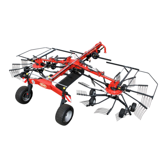
Overview Designation of Overview components Deflector bar Tine support Rotor gear Tines Steering Transport chassis Transport holder for tine supports Lifting arm Telescopic arm Rotor arm shaft Main frame Attachment carrier Sustainer Drive Swath former Deflector bar Rotor chassis... -
Page 10: Small Parts
Overview Small parts Control cables Main frame assembly material Lynch pins Lighting cable Deflector bar assembly material Gear box assembly material... -
Page 11: Crate Packaging
Overview Crate packaging Overview of assembly groups Transport chassis Right lifting arm Rotor Bearing housing Hydraulic cylinder Lifting arm console Left lifting arm Front main frame Intermediate shaft Attachment carrier Rotor gear Rotor chassis Assembly group Page Fitting the attachment carrier Connecting the main frame to the transport chassis. -
Page 12: Pallet Packaging
Overview Pallet packaging Overview of assembly groups Wheel Transport chassis Right lifting arm Left lifting arm Wheel hub Rotor chassis Front main frame Side shaft Assembly group Page Connecting the front main frame to the rear main frame. Fitting the wheels onto the transport chassis. Fitting the rotor chassis onto the rotor gear. -
Page 13: Crate Packaging
Crate packaging Requirements • Suitable flat surface approx. 10 x 10 m as assembly space. Crate packaging • Lifting gear with lifting accessories for at least 1,500 kg • Floor conveyor (pallet truck or fork lift) with a fork length of at least 1,800 mm. -
Page 14: Main Frame
Crate packaging Main frame Use suitable lifting accessories to remove the frame elements from the crate. Loosen all fastenings (wires, lashing straps). Fitting the Fit the attachment carrier to the main frame. To do this, proceed as follows: attachment carrier ... - Page 15 Crate packaging Attachment carrier assembly drawing Dowel pins Attachment carrier Front main frame Drive in the dowel pins at 90° to each other.
- Page 16 Crate packaging Fitting the transport chassis Fitting the transport chassis to the main frame. Steering arm Raise the frame of the transport chassis and screw it to the rear main frame (torsion-free). Raise the main frame and transport chassis. ...
- Page 17 Crate packaging Transport chassis assembly drawing Spacer sleeve M 16 x 140 290 Nm Dowel pins Spacer sleeve Wheel chock 290 Nm M 16 x 80 Reflector (35 cm above driving surface) M 16 x 120 290 Nm Drive in the dowel pins M 18 x 1.5 wheel nuts...
- Page 18 Crate packaging Fitting the main Screw both parts of the main frame together at the flange piece. frame Please note: First guide the inside hydraulic and electrical lines through the openings in the flange pieces of the two main frames. Use the internal assembly cable for the electrical line.
- Page 19 Crate packaging Main frame assembly drawing Rear main frame Front main frame Tine cover holder Clamping sleeve 290 Nm Nuts and washers 3 hydraulic lines Bolts and washers 1 electrical line First thread the electrical lines (lighting cables) from the front to the rear through the front main frame.
- Page 20 Crate packaging Fitting the hose guide Fit the hose guide and cable guide to the attachment carrier. Cable guide Hose guide Quantity Part Hose guide and cable guide Perforated plate M 10 x 30 mushroom head bolts 11 x 20 x 2 washers Self-locking nuts...
-
Page 21: Steering
Crate packaging Steering The rear steering rod is fitted to the swinging arm. The front steering rod is fitted onto the attachment carrier. Fit and attach the other steering rods as follows. Use a grease gun to grease all of the pins. ... - Page 22 Crate packaging Fitting the left and right steering rod Connect the rear and left steering rods with the swinging arm. The steering is preset at the factory. Right steering rod Connect and align the right steering rod with the swinging arm. ...
- Page 23 Crate packaging Fitting the steering rods to the transport chassis Connect the right and left steering rods to the lever on the transport chassis. Ensure that the wheels are positioned correctly. Right steering rod Lever Straighten up the transport chassis wheels . ...
- Page 24 Crate packaging Connecting the steering rods The steering is preset at the factory. Fit the lower part of the bearing shells to the main frame. Rear steering rod Place the steering rod into the bearing shells. Connect the clevis of the rear steering rod with the adapter of the front steering rod.
-
Page 25: Lifting Arms
Crate packaging Lifting arms Fit the lifting arms with hydraulics and the transport locking bars for both rotors to the main frame. Secure the lift arms and the hydraulic cylinders using suitable lifting accessories. Lifting arm console Right lifting arm Flange bearing Left lifting arm Bearing shaft... - Page 26 Crate packaging Fitting the lifting Fit the lifting arms in a position whereby the bearing shafts for fitting the rotors point forwards. arms See the overview on page 26. When fitting them, secure the lifting arms using suitable lifting accessories and stands.
- Page 27 Crate packaging Insert M 12 bolts. Screw the flange pieces tight (torsion-free). M 12 bolt 120 Nm Quantity Part Lifting arms Flange piece 50 x 62 x 1 shims 50 x 62 x 3 supporting discs M 12 x 50 bolts M 8 x 50 bolts M 12 washers M 8 washers...
-
Page 28: Hydraulics
Crate packaging Hydraulics Fitting the lift limiter and hydraulic cylinder Grease the pins with a brush. Insert the pin between the hydraulic cylinder and the lifting arm console. Fit the lift limiters. When doing so, make sure that the lift limiters do not jam. - Page 29 Crate packaging Fitting the piston rod Pull the piston rod of the hydraulic cylinder up to the mounting point on the lifting arm. Piston rod Push the bleed valve on the hydraulic cylinder and pull out the piston rod. ...
-
Page 30: Laying The Hydraulic Lines
Crate packaging Laying the Lay the hydraulic hoses and secure using cable ties. hydraulic lines Correctly guide the hydraulic lines through the chain links. Fit the scouring protection coil. Observe the labelling of the hydraulic hoses. See »Raising the lifting arms«, page 31. - Page 31 Crate packaging Raising the lifting Plan overview for connecting to tractor's single-acting hydraulic control unit. arms Hydraulic cylinder Hydraulic cylinder for swath former Ball valve Telescoping the Plan overview for connecting to tractor's double-acting hydraulic control unit. lifting arms “Slave”...
- Page 32 Crate packaging Electrohydraulic Connection to solenoid valves and pilotbox control and tractor's single-acting hydraulic control unit. single lift [+] For assembly, see »Fitting the electrohydraulic single lift [+]«, page...
-
Page 33: Lighting Equipment And Electrics
Crate packaging Lighting equipment and electrics Lighting cables and Loosen the bolts on the warning signs. warning signs Insert the warning sign into the keyhole on the main frame with bolts and allow to lock into place at the bottom. Transport chassis Keyhole Illuminated warning signs... - Page 34 Crate packaging Laying the lighting Lay and connect up the lighting cables of the rear light as illus- trated. cables for the Connect both of the short lighting cables to the rear lights. Lead the lighting equipment plugs through the opening in the transport chassis beneath the frame.
- Page 35 Crate packaging Laying the lighting Lay the lighting cable and hydraulic hoses as illustrated and secure using cable ties. cable and hoses on Lay the control cables as illustrated and secure using cable the attachment stoppers. carrier See »Control cable«, page 39. ...
-
Page 36: Swath Former
Crate packaging Swath former The swath former is fitted under the main frame. The control arms for the swath former are fitted to the swath former holder. Front main frame Rear main frame Hydraulic cylinder Spring Control arm with hydraulic cylinder Control arm ... - Page 37 Crate packaging Fitting the control Attach both control arms under the main frame using pins and washers. Secure the pin with a split pin. Place the hydraulic cylinder under the main frame using pins and washers. Connect the piston rod pin to the rear control arm. ...
- Page 38 Crate packaging Fitting the swath Place the swath former between the control arms and insert the bolt, washer and spacer tube. former Fit the swath former in the hole pattern shown below and screw tight. Control arm Swath former Bolt and Spacer tube washer...
- Page 39 Crate packaging Connecting the swath former hydraulics Connect the hydraulic hose on the swath former hydraulic cylinder to the T-piece. T-piece Hydraulic cylinder Control cable For both lifting arms, hitch the control cable to the transport locking bar and guide through the ceramic eyelet. Control Ceramic eyelet ...
-
Page 40: Parking Stands
Crate packaging Parking stands Fitting the parking stands Mount the parking stands for the tine supports beneath the main frame and beneath the transport chassis. When fitting the parking stands, make sure that they are parallel. Parking stands Bolt Washer Self-locking nuts Parking stands Quantity... -
Page 41: Rotor
Crate packaging Rotor Fitting the rotor The rotor gears are pre-fitted on the rotor chassis. Rotor gear Wheel 20 Nm wheel nut Quantity Part Pre-assembled rotor chassis with rotor gear 16 x 6.5 wheels Cover caps... - Page 42 Crate packaging Fitting the wheels Fit the wheels onto both rotor chassis. Tighten the wheel nuts on the wheels to 20 Nm. Fit the wheel caps to the wheels. Adjust the rotor pitch on all wheel carriers in advance. ...
- Page 43 Crate packaging Fitting the bearing Fit the bearing housings to both rotors. housing to the rotor Observe the "Left" sticker. Lower the bearing housing into the correct position using suitable loading accessories. Slide the rotor into the correct position. ...
- Page 44 Crate packaging Fitting the rotors Fit both rotors onto the lifting arms. onto the lifting arms Lower the lift arm into the correct position. Use a brush to grease the lift arm bearing shaft. Slide the rotor with the bearing housing into the correct position. ...
-
Page 45: Drive
Crate packaging Drive During the fitting process, make sure that the shaft ends lock onto the PTO stub shafts. Fitting the side Use a brush to grease the PTO stub shafts. shafts Place the side shaft onto the gear box and allow to lock into place. ... -
Page 46: Protective Equipment
Crate packaging Protective Fit the protective equipment onto both rotors. equipment Left rotor Bearing housing Deflector carrier Retainer plate Deflector bar Quantity Part Deflector carrier M 12 x 35 bolts M 12 self-locking nuts M 12 washers Clamp for crank locking device Retainer plates M 12 x 55 bolts Deflector bar... - Page 47 Crate packaging Fitting the deflector Fit the deflector carrier onto the bearing housing. Insert the bolts from the outside to the inside and connect with the washer and self- carrier locking nuts. Fit the flexible shaft to the gear box and secure with a dowel pin. ...
- Page 48 Crate packaging Fitting the deflector On both rotors, fit the deflector bar onto the deflector carrier. Remove the spring, washers and split pin from the deflector bar. Push the deflector bar into the rear opening on the deflector carrier. ...
-
Page 49: Fitting The Balance Spring
Crate packaging Fitting the balance spring On both rotors, fit and adjust the balance spring. Hook the spring to the support on the rotor. Hook the eye bolt to the spring and place it through the hole. Tighten the eye bolt. •... -
Page 50: Final Assembly
Crate packaging Final assembly Proceed as follows to complete the assembly: with crate »Setting up work«, see page 60. »Accessories«, see page 65. packaging »Final operations«, see page 70. -
Page 51: Pallet Packaging
Pallet packaging Requirements • Suitable flat surface approx. 10 x 10 m as assembly space. Pallet packaging • Lifting gear with lifting accessories for at least 1,500 kg • Floor conveyor (pallet truck or fork lift) with a fork length of at least 1,800 mm. -
Page 52: Pallet Assembly
Pallet packaging Pallet assembly Use suitable lifting accessories to lift the frame elements. Loosen all fastenings (wires, lashing straps). Follow the handling instructions below. Fitting the main Screw both parts of the main frame together at the flange piece. Please note: First guide the inside hydraulic and electrical lines frame through the openings in the flange pieces of the two main frames. - Page 53 Pallet packaging Using 4 bolts, loosely connect the flange pieces from the front and Rear main frame rear main frames. Secure the flange pieces using 2 clamping sleeves (torsion-free). Insert the remaining bolts. Connect the flange pieces using 12 bolts (torsion-free). Front main frame Front main frame Rear main frame...
- Page 54 Pallet packaging Fitting the transport chassis Lift the main frame with transport chassis using suitable lifting accessories and secure. Transport chassis Use a brush to grease the bushes of the wheel hub. Fit the wheel hub onto the axles. Axle ...
-
Page 55: Hydraulics
Pallet packaging Hydraulics In the case of pallet packaging, the machine hydraulics are completely connected up. Couple the machine to the tractor. Do not couple the PTO shaft. Connect the machine hydraulics to the tractor. Position the main frame horizontally with the tractor's power lever. Please note the instructions for commissioning in the »Final operations«... -
Page 56: Fitting The Rotor Chassis
Pallet packaging Fitting the rotor The rotor gears are pre-fitted on the two lifting arms. Proceed as follows: chassis Fit the wheels onto both rotor chassis. See »Fitting the wheels«, page 42. Use the tractor's hydraulic control unit to fold back the lift arms until the underside of the rotor gears is approx. - Page 57 Pallet packaging Fitting the rotor onto Use a floor conveyor to align the rotor chassis at a right angle under the rotor gear, and slowly lift until the spindle for the working the chassis depth sits on the profile shaft of the rotor gear. ...
- Page 58 Pallet packaging Fit the adjusting screw for tine lifting Fit the gaiter onto the rotor chassis. Gaiter Fit the adjusting screw for tine lifting. Fit the self-locking nut to prevent the spindle turning out from the rear. The gap between the self-locking nut and the hexagonal profile is around 5 mm.
-
Page 59: Final Assembly With Pallet Packaging
Pallet packaging Final assembly Proceed as follows to complete the assembly: with pallet »Steering«, see page 21. packaging »Lifting arms«, see page 25. »Laying the hydraulic lines«, see page 30. »Swath former«, see page 36. »Drive«, see page 45. ... -
Page 60: Setting Up Work
Setting up work Length of the PTO The length of the PTO shaft was selected at the factory to suit almost Setting up work all types of tractor. Only in exceptional cases is a correction of the PTO shaft shaft length required on individual tractors. Check the length of the PTO shaft on each tractor prior to first use. - Page 61 Setting up work Shortening the PTO shaft Pull the PTO shaft apart and connect one half to the tractor PTO shaft drive and the other half to the machine and secure them. Place the two shaft halves next to each other and: •...
-
Page 62: Steering
Setting up work Steering The steering is preset at the factory. If the factory setting needs to be modified, the lock nut must be used to secure the steering rod from being twisted. Checking the track If the machine rolls at an offset angle to the tractor when driving a straight line, the directional stability is set incorrectly. -
Page 63: Fitting The Tine Supports
Setting up work Fitting the tine supports Loosen and remove the lynch pin from the tine support. Lynch pins Rear hole Secure the lynch pin in the rear hole of the tine support. Fit the tine supports. ... -
Page 64: Adjusting The Rotor Pitch
Setting up work Adjusting the rotor pitch It is possible to adjust the position of the rotors laterally to the direction of travel. Undo the four bolts on the wheel carrier slightly. Push the wheel carriers into the required position (see graphic below). -
Page 65: Accessories
Accessories Electrohydraulic The electrohydraulic single lift enables the deposit of the crop with one Accessories rotor. single lift [+] Fitting the electrohydraulic single lift [+] Fit the solenoid valves and the electrical plugs to the hydraulic block. Hydraulic block holder ... - Page 66 Accessories Ball valve Lifting arm console Hydraulic block Solenoid valve Hydraulic block holder Electrical plug Control box...
-
Page 67: Spare Wheel [+]
Accessories Spare wheel [+] Fit the spare wheel to the machine. Spare wheel Tine saver [+] For a good swath deposit, both tine legs must run parallel to one another after fitting the tine saver. Fit one tine saver for each tine pair. ... -
Page 68: Circuit Diagrams
Circuit diagrams Hydraulics circuit Circuit diagrams diagram Left lifting arm Right lifting arm Swath former Lift arm extension Restrictor Restrictor 1.5 mm 1.5 mm Restrictor Electrohydraulic single lift 0.5 mm Tractor hydraulics... -
Page 69: Lighting Equipment Circuit Diagram
Circuit diagrams Lighting equipment circuit diagram 2/54g 3/31 5/58R 6/54 7/58L Connecting plug 7-pin in accordance with ISO 1724 Yellow Green White Brown Black Connectors and sockets 7-pin in accordance with ISO 1724 Yellow Black Right indicator Right brake light Earth Left indicator Right rear light... -
Page 70: Final Operations
Final operations Introducing air to The lifting arm hydraulic cylinders need a cushion of air to enable them Final operations to function properly, such as folding out on a slope. Proceed as the hydraulic follows: cylinder Couple the machine to the tractor. ... -
Page 71: These Assembly Instructions 5 Trial Run
Final operations Trial run No persons within the slewing range There is an extreme risk of injury within the slewing range from slewing or folding machine parts. Referring to the operating manual, adjust the machine and carry out a trial run. ...
Need help?
Do you have a question about the Andex 844 and is the answer not in the manual?
Questions and answers