
Related Manuals for Vicon Andex 353


Summary of Contents for Vicon Andex 353
- Page 1 Andex 353 Operating manual Original operating manual Edition 06.2012 Date of print 05.2012 Language Machine number VF69508670 Model VF6950 Document number VF16649742.EN...
- Page 2 Machine identification In order for your dealer to assist you as efficiently as possible, you will need to provide some information about your machine. Please enter the details here. Designation Andex 353 Working width 3.50 m Weight 420 kg Machine...
-
Page 3: Table Of Contents
Table of contents Table of contents Preface ............Cleaning and care ........53 Target group for this operating manual Safety Symbols used Cleaning Care Safety ............For your safety Parking and storage ........55 Who is authorised to operate the machine? 9 Setting down the machine in a... -
Page 4: Preface
Preface Target group for This operating manual is intended for trained farmers and individuals Preface who are otherwise qualified to perform agricultural activities and who this operating have received instruction in the operation of this machinery. manual For your safety You must familiarise yourself with the contents of this operating manual before assembly or initial operation of the machine. -
Page 5: Symbols Used
Preface Symbols used In this operating manual, the following symbols and terms have been used: • A bullet point accompanies each item in a list. A triangle indicates operating functions which must be performed. An arrow indicates a cross-reference to other sections of this manual. -
Page 6: For Your Safety
Safety For your safety This chapter contains general safety instructions. Each chapter of the Safety operating manual contains additional specific safety information which is not described here. Observe the safety information: • in the interest of your own safety. • in the interest of the safety of others. - Page 7 Safety Warning signs Safety-related labels attached to the machine indicate potential hazards. The labels must not be removed. Illegible or missing labels should be replaced. You can obtain new labels as spare parts from your dealer. Warning signs on the machine...
- Page 8 Safety Meaning of warning signs Read the operating manual Read and follow the operating and safety instructions before using the machine for the first time. The machine must not be used for the first time until the operating manual has been read and understood. This applies in particular to the safety information.
-
Page 9: Who Is Authorised To Operate The Machine
Safety Who is authorised Only qualified personnel Only qualified persons who have been informed of the dangers to operate the associated with handling the machine are permitted to operate, machine? service or repair the machine. The necessary knowledge can be gained in the course of agricultural vocational training, professional training or intensive instruction. - Page 10 Safety Switch off the PTO shaft drive when lifting the machine Switch off the PTO shaft drive on the tractor if there are people present who might enter the working area of the machine while it is being lifted. Rotating, unprotected parts can damage the machine and cause life- threatening injuries.
- Page 11 Safety Never work on the machine while it is running No operations may be performed on the machine while it is running. Objects or persons can be caught, drawn in or crushed. Serious or fatal injury may be caused as a result. Safety distance from raised and unsecured loads Never work under suspended loads.
-
Page 12: Coupling
Safety Coupling Increased risk of injury When the machine is being coupled to the tractor, there is an increased risk of injury. Therefore: • Secure the tractor against rolling away, shut off the engine and remove the ignition key. • Never stand between the tractor and machine. -
Page 13: Road Transport
Safety Road transport Ensuring road safety The machine must conform to current national traffic regulations if you intend to drive with it on public roads. Ensure the following: • Lighting, warning and protective equipment must be fitted • The permissible transport widths and weights, axle loads, tyre load-bearing capacities, laden weights and national speed restric- tions must be complied with. - Page 14 Safety Speed adjustment In poor road conditions and at high speeds, significant forces can be generated which subject the tractor and machine material to high or excessive stresses. Adjust your driving speed to the road conditions. A driving style which is not adapted to conditions can cause accidents. Accidents with serious or fatal injuries may be caused as a result.
-
Page 15: Operation
Safety Operation Operate for the first time only after proper training The machine may only be put into operation after proper training has been provided by an employee from a dealership or the manufacturer, or by a factory representative. Operation without training can lead to damage to the machine due to incorrect operation, or cause accidents. -
Page 16: Uncoupling
Safety Uncoupling Increased risk of injury There is an increased risk of injury when uncoupling the machine from the tractor. Therefore: • Secure the tractor against rolling away, turn off the engine and remove the ignition key. • Never stand between the tractor and machine. •... -
Page 17: Care And Maintenance
Safety Care and Observe the care and maintenance intervals Observe the periods specified in the operating manual for recurrent maintenance checks and inspections. If these periods are not observed, damage to the machine and accidents may be caused as a result. Use original parts Many components have special properties that are essential for the stability and correct operation of the machine. -
Page 18: Further Regulations
Safety Further Observe the regulations In addition to the safety information given above, please observe the regulations following: • Accident prevention regulations. • Generally recognised safety regulations, occupational health requirements and national road traffic regulations. • The instructions provided in this operating manual. •... -
Page 19: Getting To Know The Machine
Getting to know the machine Range of This product is classified as replaceable equipment in accordance Getting to know the machine with EC directive 2006/42/EC. application The machine is a single-wheel rake, which is suitable only for the raking together of mown, stalked material (for example, hay or straw). Proper use Any other use, for example, for silo distribution, any form of soil prep- aration, road sweeping or for the transmission of power to other... -
Page 20: Component Designations
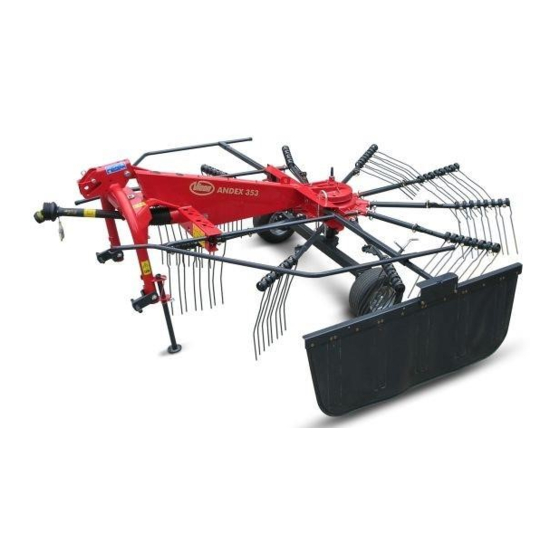
Getting to know the machine Component designations Deflector bar Tine supports Rotor gear Tines Rotor chassis Main frame Transport locking bar Attachment Drive Parking Transport holder for Transport locking device Swath former carrier stand tine supports for tine supports... -
Page 21: Technical Specifications
Getting to know the machine Technical specifications Dimensions in transport position Model 6950 Length 3.33 m Height 1.70 m Transport width 1.73 m Height of bottom reflectors 0.40 m Distance between bottom reflectors 1.10 m Track 1.55 m Distance, machine's centre of gravity 1.05 m... - Page 22 Getting to know the machine Dimensions in work position Model 6950 Length 3.33 m U’ Swath width 2.65 m Working width 3.50 m U’...
- Page 23 Getting to know the machine Weights Model 6950 Total weight 420 kg Load supported on parking stand 160 kg Required tractor equipment Output / connections Minimum output of the tractor 20 kW (28 hp) Lighting power supply 12 V, 7-pin plug socket ISO 1724 Maximum PTO shaft speed 540 rpm Lower link...
- Page 24 Getting to know the machine Machine equipment Model 6950 Swath deposit Swath former Standard Rotors / tine supports / tines Number of rotors Number of tine supports per rotor Number of tines per tine support Removable tine supports Standard Rotor height adjustment Mechanical Tine saver Crank extension...
-
Page 25: Centre Of Gravity Considerations
Getting to know the machine Centre of gravity Observe the total weight, axle loads, tyre load-bearing capacity and minimum ballast specifications. considerations The front or rear attachment of machines must not cause the tractor's permissible total weight, its permissible axle load or its tyre load- bearing capacity to be exceeded. - Page 26 Getting to know the machine Calculation The values (A) to (I) can be inserted in the formulas. Ballast with front Calculation of the ballast with front weights for rear-mounted weights machines. D X (I + G) – (B X H) + (0.2 X A X H) Front ballast in kg: F + H Ballast with rear weights...
-
Page 27: Delivery And Assembly
Delivery and assembly Checking the Delivery is in the fully assembled state Delivery and assembly The machine is delivered fully assembled. Using the check list, check scope of delivery the loose parts on delivery. If any parts of the machine have not been fitted or are missing, please contact your dealer. -
Page 28: Pto Shaft Length
Delivery and assembly PTO shaft length The length of the PTO shaft has been selected at the factory to suit almost all types of tractor. Only in exceptional cases is a correction of the PTO shaft length required on individual tractors. Check the length of the PTO shaft for each tractor prior to first use. - Page 29 Delivery and assembly Shortening the PTO shaft Pull the PTO shaft apart and connect one half to the tractor PTO shaft drive and one to the machine and secure them. Place the two shaft halves next to each other and: •...
-
Page 30: Coupling The Machine
Coupling the machine Safety Coupling the machine Observe the safety information Observe the safety information. Disregard for safety information can lead to serious or fatal injury. See chapter »Safety«, page 6. Increased risk of injury When the machine is being coupled to the tractor, there is an increased risk of injury. -
Page 31: Coupling The 3 Point Trestle
Coupling the machine Coupling the 3 The machine is equipped ex-factory for coupling to the 3 point trestle of category I and category II tractors. point trestle Adjusting the hitch For use on category I tractors, proceed as follows: Remove the split pin on the first clevis of the 3 point trestle (cf. illus- tration). -
Page 32: Inserting The Parking Stand
Coupling the machine Coupling the top link When coupling the top link, ensure that the hitch pin is correctly fitted (see illustration opposite). Hitch without Please note the following (otherwise, the machine may be contact roller damaged): With the optional contact roller, insert the hitch pin for the top link into the elongated hole and secure using a safety splint. -
Page 33: Coupling The Pto Shaft
Coupling the machine Coupling the PTO shaft When coupling the PTO shaft, make sure it is in the correct position. Tractor Check whether the PTO shaft must be shortened before coupling. Shorten the PTO shaft if necessary. »PTO shaft length«, page 28 ... -
Page 34: Preparing For Use
Preparing for use Safety The following applies to all preparations for operation: Preparing for use Observe the safety information Observe the safety information. Disregard for safety information can lead to serious or fatal injury. See chapter »Safety«, page 6. Secure the machine Secure the machine against accidental starting and rolling away. -
Page 35: Rotor Pitch
Preparing for use Rotor pitch The rotor is inclined obliquely to the chassis. The rotor is already inclined obliquely ex-factory. If the crop is not picked up cleanly, the raking quality can be improved by adjusting the rotor pitch. The rotor pitch is adjusted as follows: ... -
Page 36: Working Depth
Preparing for use Working depth The working depth is adjusted manually using a crank. Adjust the working depth as follows: Fully lower the machine using the tractor's hydraulic control device. Crank Switch off the tractor and secure it. ... -
Page 37: Tine Saver [+]
Preparing for use Tine saver [+] If the tines are broken, the tine saver can prevent the broken-off part Breaking point from being lost. Any machines following behind, for example straw cutters, are then not damaged by lost tines in the crop. Tine leg For a good swath deposit, both tine legs must run parallel to one an- other after the tine savers have been fitted. -
Page 38: Road Transport
Road transport Safety Before transporting the machine on public roads, please read the Road transport following safety information. Compliance is mandatory and will help you to avoid accidents. Observe the safety information Observe the safety information. Disregard for safety information can lead to serious or fatal injury. -
Page 39: Prior To Road Transport
Road transport Prior to road Prior to driving on public roads, the machine must be folded in, secured and moved into the transport position: transport »Fold in the deflector bar« »Removing the tine supports« »Bring the machine into the transport position« ... - Page 40 Road transport Fold in the deflector Fold in the deflector bar as follows: Right deflector bar Switch off the tractor and secure it. Left deflector bar Pull the left deflector bar with swath former forwards, against the resistance of the pressure spring, and fold upwards to 90°. Pressure spring ...
- Page 41 Road transport Removing the tine For road transport, all tine supports (with the exception of the centre tine supports) are removed and stowed in the transport holder. supports Remove any crop residues and coarse dirt. Rear hole Loosen the lynch pin on the tine support. ...
- Page 42 Road transport Bring the machine Make sure the machine is standing level into the transport Before changing from the transport to the work position (and vice position versa), make sure the machine is standing level. The machine could tip over, particularly on hillside locations. The machine could be damaged and serious or fatal injuries could be caused.
-
Page 43: Road Transport
Road transport Checking the Prior to driving on the road, check the machine against the check list: machine PTO shaft drive off? Deflector bar folded? Tine supports in the transport holder and secured? Tyre pressures correct? ... -
Page 44: General
Preparations on the field Safety The following applies for all preparations on the field: Preparations on the field Observe the safety information Observe the safety information. Disregard for safety information can lead to serious or fatal injury. See chapter »Safety«, page 6. Switch off the tractor and secure it Before you dismount: ... -
Page 45: Lowering Machine To The Work Position
Preparations on the field Lowering machine to the work position After road transport, the machine is brought into the work position on the field. Switch on the tractor. Lower the lower link until the machine rests on the wheels. ... -
Page 46: Basic Settings
Preparations on the field Basic settings Fitting the tine supports Remove the tine supports from the transport holder. Attach the tine supports to the support bar and secure with lynch Rear hole pins. Tine supports Lynch pin... - Page 47 Preparations on the field Folding out the No persons within the slewing range deflector bar There is an acute risk of injury within the slewing range from machine parts which are slewing or folding. Serious or fatal injury may be caused as a result. After the tines have been attached, all guard devices must be moved from the transport to the work position.
- Page 48 Preparations on the field Adjusting the swath The swath former is folded into the correct position when changing from the transport to the work position. former Adjusting the swath former's direction of travel It is possible to adjust the direction of travel of the swath former as follows: ...
-
Page 49: Operation
Operation Safety Operation Observe the safety information Observe the safety information. Disregard for safety information can lead to serious or fatal injury. See chapter »Safety«, page 6. No riding on the machine Persons or objects must never be transported on the machine. Carrying passengers on the machine is life threatening and prohibited. -
Page 50: General
Operation General The following work steps are described in this section: • »Swathing« • »Driving on headlands« Suitable working speeds Select a driving speed (approx. 4-12 km/h) at which the crop is picked up cleanly and completely. The working speed depends on the machine settings and the particular crop. -
Page 51: Swathing
Operation Swathing No persons in the working area Ensure that no persons are present in the slewing and working area of the machine. Persons could be caught by the machine within this area. This could result in fatal injury. Requirements After setting the machine as described in chapter »Preparations on the field«... -
Page 52: Swath Deposit
Operation Swath deposit The following swath deposits are possible: Single swath Night swath Swath turning Double swath Multiple swath Driving on headlands The rotor can be raised for crossing swaths that have already been harvested. Raise the machine to the headland position using the tractor's lower link control device. -
Page 53: Cleaning And Care
Cleaning and care Safety The following applies to all cleaning and care work: Cleaning and care Observe the safety information Observe the safety information. Disregard for safety information can lead to serious or fatal injury. See chapter »Safety«, page 6. Secure the machine •... -
Page 54: Cleaning
Cleaning and care Cleaning Lower the machine to the work position. After each use, clean the machine of any coarse dirt and crop residues. After cleaning Lubricate all bearings after cleaning. Care For a long service life, we recommend the following: ... -
Page 55: Parking And Storage
Parking and storage Setting down the When setting down and parking the machine, special safety Parking and storage precautions have to be observed: machine in a secure position Observe the safety information Observe the safety information. Disregard for safety information can lead to serious or fatal injury. -
Page 56: After The End Of The Season
Parking and storage After the end of After the end of the season and if the machine is to be stored for a relatively long period of time, perform the following work: the season Clean the machine thoroughly. Check all the screw joints and tighten the screws. ... -
Page 57: Maintenance
Maintenance Safety The following applies to all servicing work: Maintenance Observe the safety information Observe the safety information. Disregard for safety information can lead to serious or fatal injury. See chapter »Safety«, page 6. Requirements for maintenance work Only perform the maintenance operations if you have the required expert knowledge and suitable tools. - Page 58 Maintenance Protective measures Additives in oils and lubricants may have adverse effects on health. As marking in accordance with the hazardous goods regulation is not when handling oils or necessary, please always ensure the following: lubricants Avoid skin contact Avoid skin contact with these materials. Protect your skin by means of protective skin cream or oil-resistant gloves.
-
Page 59: General
Maintenance General This information relates to general servicing work. For all servicing work, the machine must be locked in the work position. If the transport position is required for maintenance work, refer to the relevant instruc- tions for the work. ... - Page 60 Maintenance Maintenance terms Listed in this table are short explanations of the most important maintenance terms. Task Explanation Greasing Apply grease to the slide surfaces using a brush. Lubrication One or two presses of the grease gun, unless specified otherwise. Unless specified otherwise, use only plant-based oils, such as rapeseed oils.
-
Page 61: Screwed Connections
Maintenance Screwed Use original parts Machine components have special properties that are essential for the connections stability and correct operation of the machine. Only spare parts and accessories supplied by the manufacturer have been tested and approved. Other products may adversely affect the correct operation of the machine and safety. - Page 62 Maintenance Special tightening Observe the special tightening torques for the following screwed con- nections: torques • 90 Nm spring tine. 90 Nm Spring tines 20 Nm Rotor chassis wheel nuts. 20 Nm M 12 wheel nut...
-
Page 63: Maintenance
Maintenance Lubrication points Maintenance for grease Working with the The points marked with a brush symbol should be regularly checked to ensure they move freely and lightly greased with the brush as brush required. Re-grease each time after cleaning. Ends of the tine supports... - Page 64 Maintenance Working with a The points marked with a grease gun symbol indicate lubricating nipples which are to be lubricated using the grease gun. grease gun Two lubricating nipples are located on the rotor gear and one on the contact roller [+] joint Before applying the grease gun ...
-
Page 65: Lubricating The Pto Shafts
Maintenance Lubricating the The PTO shaft manufacturer's own operating manual is included with each PTO shaft. This includes detailed information on the relevant PTO shafts version of the PTO shaft. Check the guard components Check all guard components of the PTO shafts for wear or damage (visual inspection). -
Page 66: Rotor Gear
Maintenance Rotor gear The rotor gear is equipped with a continuous oil lubrication system. The oil level must be checked if there is a visible loss of oil (oil streaks on the check screw or rotor). Move the machine into a horizontal position. ... -
Page 67: Optional Accessories
Accessories Optional You can purchase the following optional additional equipment through Accessories your dealer. accessories Contact roller The optional contact roller on the 3 point trestle makes for better contours. Please note: With the optional contact roller, insert the hitch pin for the top link into the oval hole and secure using a safety splint. - Page 68 Accessories Double stabilisers The optional double stabilisers prevent the machine losing contact with the ground when driving on slopes. Transverse support The double stabilisers are inserted into the support holes on the Fastening frame's front transverse support and are secured to the 3 point trestle using a fixing screw.
- Page 69 Accessories Warning sign set The optional warning sign set increases safety when travelling on the road. Warning sign set Lighting equipment The optional lighting equipment set increases safety when travelling on the road. Lighting equipment set...
-
Page 70: Fault Elimination
Fault elimination Faults Faults can often be eliminated quickly and easily. Before contacting Fault elimination Customer Service, refer to the table to check whether you can remedy the fault yourself. In case of a fault, proceed as follows: Immediately stop operation. ... -
Page 71: Circuit Diagrams
Circuit diagrams Lighting circuit Circuit diagrams diagram 2/54g 3/31 5/58R 6/54 7/58L Connecting plug 7-pin in accordance with ISO 1724 Yellow Green White Brown Black Connector and socket 7-pin in accordance with ISO 1724 Yellow Black Right indicator Right brake light Earth Left indicator Right rear light... -
Page 72: Decommissioning
Decommissioning Environment During decommissioning, the individual parts must be disposed of Decommissioning properly and in an environmentally friendly manner. Please observe the waste disposal guidelines that are currently in force. Plastic parts Plastic parts can be disposed of in normal household waste (residual waste), depending on the laws specific to your country. -
Page 73: Ec Conformity Declaration
Kverneland Group Kerteminde AS 2006/42/EC Taarupstrandvej 25 DK-5300 Kerteminde Denmark declare with sole responsibility that the product SwatMaster 3521 Andex 353 9035 and its accessories Model: 6950 Type plate and CE marking Valid from machine number: VF69508670 – to which this declaration relates, comply with the relevant basic health and safety requirements of EC Directive ... -
Page 74: Index
Index Index Putting away after the season Setting down Adjusting Uncoupling Chassis Maintenance Rotor pitch Lubrication points Tine saver Screwed connections Working depth Maintenance intervals Care Check list Protective measures Road transport Operation Checking the scope of delivery Circuit diagram Hydraulics Lighting equipment Preparation for road transport...
Need help?
Do you have a question about the Andex 353 and is the answer not in the manual?
Questions and answers