Table of Contents
Advertisement
Quick Links
Advertisement
Table of Contents

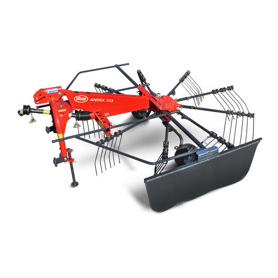
Summary of Contents for Vicon Andex 323
- Page 1 Andex 323 A s s e m b l y i n s t r u c t i o n s E d i t i o n 9 . 2 0 0 8 D a t e o f p r i n t 7 .
- Page 2 K v e r n e l a n d G r o u p G o t t m a d i n g e n N . V . F i l i a l e G o t t m a d i n g e n I n d u s t r i e p a r k 3 1 2 7 8 2 4 4 G o t t m a d i n g e n G e r m a n y...
-
Page 3: Mounting Instructions
Mounting Instructions Read and follow exactly the safety instructions in chapter 1 before beginning to assemble the machine. Please observe the tightening torques listed in the table at the end of these instructions when assembling the machine. Torques that differ are specifically mentioned in these mounting instructions. Open the crate and carefully spread out all the parts on the ground. -
Page 4: Application As Stipulated
Safety Application as stipulated Attention! For your safety Those who disregard the regulations Read and observe exactly the safety instructions mentioned above are acting with in this chapter before beginning to assemble the gross negligence. In this case the machine. machine manufacturer’s liability and Anyone involved in the assembly or installation warranty no longer applies. -
Page 5: General Safety And Accident Prevention Regulations
11. Do not leave the engine on within closed General safety and accident spaces (indoors)! prevention regulations 12. Use caution when working on machine 1. The allocation of responsibilty for the various elements operated by additional driving tasks on the machine must be clearly systems (e.g. - Page 6 Chassis Attach the wheel axle to the gearcase Use roll pins Ø 14x80 and 8x80 (7) to secure the axle. © Kverneland Gottmadingen...
- Page 7 Chassis Fit the wheel, positions 1 to 11 in sequenze. Torque of pos. 7 / M12 nut = 20 Nm! CAUTION! Mount the right/left wheels trailing in relation to the direction of travel! © Kverneland Gottmadingen...
- Page 8 Lift-arm three-point linkage Join the lift arm and three-point linkage. Insert the bolt (1), mount the disks (29x42x5) on both sides and secure with cotters. Insert the screw (2) M16x110 from above, introduce through tubes, and mount with locking nuts (washers 16x55x4 under screw and nut).
- Page 9 Mounting the p.t.o. to the implement Remove the locking screw (c) located between the guard tube (b) and the funnel (a) Twist and turn the funnel (a) and guard tube (b) until the "nose" of the sliding ring (d) lies directly over the openings on the protective funnel (arrows).
- Page 10 Guard bow, swath former Introduce the guard bow in detail view „X“ (guard hoop with swath former seat on the left-hand side). Mount the bearing shells at the front, as indicated in view „Y“ e - shim f - Screw M 6 x 80 g - Washer 6,4 x 12,5 x 1,6 h - Locking nut M 6 Mount the parts in detail view „X“...
-
Page 11: Screw Torques
Tine carrier arms Fit thrust washers Ø 35/52/3,5 to the carrier tubes (gearcase). Fit tine carrier arms to the carrier tubes. Secure tine carrier arms with bolts M12x75, securing nuts M12 and two shims per arm. Tightening torque = 110 Nm. 110 Nm (81,2 ft.lbs) Screw torques 10.9...


Need help?
Do you have a question about the Andex 323 and is the answer not in the manual?
Questions and answers