Fukuda Denshi DynaScope 7000 Series Service Manual
Patient monitor
Hide thumbs
Also See for DynaScope 7000 Series:
- Operation manual (475 pages) ,
- Operation manual (177 pages)
Table of Contents
Advertisement
Quick Links
D
y
n
a
S
D
y
n
a
S
P
a
P
a
D
S
-
D
S
-
Service Manual
DS-7000, HU-71/72/73, MGU-701/702
Before using this device, read this manual thoroughly.
Keep this manual near the device for future reference.
c
o
p
e
7
c
o
p
e
7
t
i
e
n
t
M
t
i
e
n
t
M
7
0
0
0
7
0
0
0
0
0
0
S
e
r
0
0
0
S
e
o
n
i
t
o
r
o
n
i
t
o
r
S
y
s
t
e
S
y
s
t
e
i
e
s
r
i
e
s
m
m
Advertisement
Chapters
Table of Contents

Related Manuals for Fukuda Denshi DynaScope 7000 Series


Summary of Contents for Fukuda Denshi DynaScope 7000 Series
- Page 1 Service Manual DS-7000, HU-71/72/73, MGU-701/702 Before using this device, read this manual thoroughly. Keep this manual near the device for future reference.
- Page 2 • The company and product names used in this manual are trademarks or registered trademarks. • If this manual has pages missing or out of order, contact Fukuda Denshi for replacement. • Only physician or persons instructed by physicians are allowed to use the equipment.
- Page 3 Development & Production Support Dept. Fukuda Denshi Co., Ltd. 2-35-8 Hongo Bunkyo-ku, Tokyo 113-8420 Japan Received by of (Company/Hospital)
- Page 4 Revision History Equipment DS-7000 System Service Manual Edition Revised Items Reason of the Revision Date – New Edition 2008.05...
-
Page 5: Table Of Contents
Preface Thank you for purchasing this product. Before using this product, read the following precautions to make sure the product is used correctly and safely. ・・・・・・・・・・・・・・・・・・・・・・・・・・・・・・・・ Safety Precautions ・・・・・・・・・・・・・・・・・・・・・・・・ Labels Attached to the Unit ・・・・・・・・・・・・・ Measurement Unit for Each Parameter ・・・・・・・・・・・・・・・・・・・・・・・・・・・・・・... -
Page 6: Safety Precautions
Safety Precautions Read the “Safety Precautions” thoroughly before use to ensure correct and safe use of the product. Be sure to follow the precautions indicated below, as these are important messages related to safety. Failure to follow this message may cause immediate threat of death or serious D A N G E R injury, or complete failure of the equipment. - Page 7 DS-7000 Patient Monitor DANGER Risk of explosion if used in the presence of flammable anesthetics. CAUTION Before connecting, read instruction manual. CAUTION To reduce the risk of electric shock, do not remove the cover. Refer servicing to qualified service personnel. HU-71/HU-72/HU-73 Option Unit DANGER Risk of explosion if used in the presence of flammable anesthetics.
- Page 8 MGU-701/MGU-702 Multigas Unit DANGER Risk of explosion if used in the presence of flammable anesthetics. CAUTION Before connecting, read instruction manual. CAUTION To reduce the risk of electric shock, do not remove the cover. Refer servicing to qualified service personnel. <MGU-701>...
-
Page 9: Measurement Unit For Each Parameter
Measurement Unit for Each Parameter The measurement units for this equipment are as follows. Detail Parameter Display Unit Default (beats per minute) Invasive Blood Pressure PR-IBP Heart Rate / Pulse (beats per minute) Rate PR-SpO (beats per minute) Non-Invasive Blood PR-NIBP Pressure (beats per minute) - Page 10 Detail Parameter Display Unit Default Mixed Venous Oxygen Saturation Central Venous Oxygen ScvO Saturation Arterial Oxygen Saturation Oxygen Uptake Index Oxygen Transport mL/minute Oxygen Consumption mL/minute Stroke Volume Stroke Volume SV-STAT (STAT Mode) Stroke Volume Index mL/m Stroke Volume Index SVI-STAT mL/m (STAT Mode)
- Page 11 Detail Parameter Display Unit Default Cardiac Output L/min (Average Mode) Cardiac Index L/min/m Cardiac Output (Fast Mode) CO-F L/min Carbon Dioxide Emission mL/min Minute Ventilation L/min Alveolar Minute Ventilation MVAL L/min Expiratory Tidal Volume TV-E Inspiratory Tidal Volume TV-I Peak Inspiratory Pressure Mean Airway Pressure Peak End Expiratory PEEP...
-
Page 12: Graphic Symbols
Graphic Symbols The following symbols are used for this equipment. DS-7000 Main Unit Symbol Description Caution; refer to accompanying documents Indicates the need to refer to related accompanying documents before operation. Equipotential Terminal Indicates the terminal to equalize the potential difference when interconnecting the devices. -
Page 13: Precautions For Safe Operation Of Medical Electrical Equipment
Precautions for Safe Operation of Medical Electrical Equipment Read the following precautions thoroughly to correctly operate the device. Users should have a thorough knowledge of the operation before using this system. Pay attention to the following when installing and storing the equipment. Do not install or store in an area where the equipment will be subject to splashing water. -
Page 14: Precautions For Safe Operation Of Medical Telemetry
When interference or breakdown occurs in telemetry communication, the user is required to inform the zone manager and the overall manager of the problems. The zone manager and overall manager are to deal with the problem properly and/or contact their nearest Fukuda Denshi representative for service. -
Page 15: Precautions About The Maintenance
Maintenance, Modifications, and Repairs Fukuda Denshi is liable for the safety, reliability, and performance of its equipment only if; Maintenance, modifications, and repairs are carried out by authorized personnel. Components are used in accordance with Fukuda Denshi operating instructions. -
Page 16: Precautions About The Pacemaker
If such event occurs, please disconnect the cardiac monitoring and diagnostic equipment, or follow the procedures described in the operation manual of the pacemaker. (For more details, contact FUKUDA DENSHI personnel, your institution’s professionals, or your pacemaker distributors.) Reference W A R N I N G “Minute Ventilation Rate-Adaptive Pacemakers”... -
Page 17: Electrosurgery Safety
Electrosurgery Safety The monitoring system contains protection against interference generated by electrosurgical instruments. However, operating conditions, surgery site with respect to the location of ECG electrodes, or the type of instrument used, may cause noise on the ECG. The noise is generated at the tip of an electrical knife and is difficult to completely eliminate because of the frequency components of the ECG. -
Page 18: Precautions About Connections To Peripheral Devices
Fukuda Denshi. It is the user’s responsibility to contact Fukuda Denshi to determine the compatibility and warranty status of any connection made to another manufacturer’s equipment. -
Page 19: Precautions About The Ds-7000
The DS-7000 is not intended for use with flammable anesthetic agents. Do not connect unit or cable not authorized by Fukuda Denshi to any I/O connector. If done so by mistake, the DS-7000 cannot deliver its maximum performance and the connected units may be damaged, resulting in a safety hazard. - Page 20 When using the airway adapter, always consider the circumference of the intubation tube. If inappropriate airway adapter is used for a patient with low ventilation, CO may mix in to the inspired air resulting in incorrect measurement, or apnea detection may become difficult. When multigas unit (MGU-701/MGU-702/Poet IQ) is used, the sampling tube may get clogged by the internal condensation.
- Page 21 Systems This equipment is intended to be used for only one patient. The installation of this equipment should be performed by a person who is well acquainted with this equipment. The users should not attempt internal switch setting. The users should not attempt software upgrading. Use only the accessories specified for this device.
- Page 22 When arrhythmia is present, HR measurement accuracy may be degraded. Select the appropriate lead for ECG1, 2 to be used for arrhythmia detection, telemeter, central monitor transmission, and recording. The selected lead for ECG l, 2 will be used for recall waveform and recording waveform as well as for arrhythmia analysis.
- Page 23 Direct sunlight to the sensor area can cause a measurement error. Place a black or dark cloth over the sensor. When not performing the measurement, unplug the relay cable and sensor from the SpO connector. Otherwise, the measurement data may be erroneously displayed by the ambient light.
- Page 24 The Dyna Alert will not properly function for the following cases. If peripheral circulatory insufficiency or very low BP is developed. If highly-frequent arrhythmia is generated. If an artificial heart lung machine is used. If a large noise from body movement or electric surgery equipment is interfering.
- Page 25 System Configuration If the time/date is not correctly set, or if changed during monitoring, malfunction may occur to NIBP measurement, periodic recording, trend, NIBP list data, and age calculation from the birth date. When the waveform and numeric data display for each parameter is set to OFF, the alarm generation and table/trend input for the corresponded parameter will be also set to OFF.
-
Page 26: Precautions About The Wired Network System (Ds-Lan Ιι)
Do not use organic solvents, thinner, toluene and benzene to avoid damaging the resin case. Do not polish the housing with abrasive or chemical cleaner. When sterilizing the entire room using a spray solution, pay close attention not to have liquids get into the equipment or connectors. Use only neutral detergent to clean the housing. - Page 27 When DS-5800N/NX/NX is used as a central monitor, recall, trend/table, data will not be displayed. Also, Σ recording cannot be performed. For the ST display, overlap waveform will not be displayed on the DS-5800N/NX/NX until 15 minutes elapses since the reference waveform is set on the DS-7000.
-
Page 28: Precautions About The Wireless Network System
Precautions about the Wireless Network System When monitoring a patient with wireless telemetry, make sure the patient D A N G E R data is properly received at the central monitor. Pay special attention when channel ID at the bedside monitor is changed. A password can be set to access the channel ID setup menu to allow only the telemetry channel administrator to change the channel ID. -
Page 29: Precautions About The Ventilator Monitoring
In SpO monitoring, always use the sensor/relay cable specified by Fukuda Denshi. If any other sensor/relay cable is used, a high temperature D A N G E R rise of the sensor may place the patient in danger of burns. -
Page 30: Precautions For Masimo Model: Ds-7000M
® Precautions for Masimo Model: DS-7000M No Implied License Possession or purchase of this device does not convey any express or C A U T I O N implied license to use the device with unauthorized sensors or cables which would, alone, or in combination with this device, fall within the scope of one or more of the patents relating to this device. -
Page 31: Electromagnetic Compatibility
Electromagnetic Compatibility The performance of this device under electromagnetic environment complies with IEC60601-1-2 (2001). Precautions for Safe Operation under Electromagnetic Influence If any sorts of electromagnetic wave, magnetic field, or static electricity exist around the device, noise interference or malfunction of the device may occur. If any unintended malfunction or noise occurs during monitoring, check the magnetic influence and take appropriate countermeasures. -
Page 32: Compliance To The Electromagnetic Emissions
●Compliance to the Electromagnetic Emissions The DS-7000 is tested under the following electromagnetic environment. Emissions Test Compliance Electromagnetic Environment – Guidance The DS-7000 is intended for use in the electromagnetic environment specified below.) The equipment uses RF energy that is necessary for the internal RF Emissions functioning of the equipment itself. -
Page 33: Compliance To The Electromagnetic Immunity
●Compliance to the Electromagnetic Immunity (2) The DS-7000 is tested under the following electromagnetic environment. Electromagnetic Environment - Guidance IEC60601-1-2 Compliance The DS-7000 is intended for use in the Immunity Test Test Level Level electromagnetic environment specified below.) Portable and mobile RF communications equipment should be used no closer to any part of the DS-7000, including cables, than the recommended separation distance calculated... -
Page 34: Recommended Separation Distances Between Portable And Mobile Rf Communications Equipment And The Ds-7000
●Recommended Separation Distances between Portable and Mobile RF Communications Equipment and the DS-7000 The DS-7000 is intended for use in an environment in which radiated RF disturbances are controlled. The electromagnetic interference can be prevented by maintaining a minimum distance between portable and mobile RF communications equipment (transmitters) and the DS-7000 as recommended below, according to the maximum output power of the communications equipment. - Page 35 Contents Preface 1. General Description Provides an overview of the DS-7000 system. 2. Specification Lists electrical and mechanical specification. 3. Names of Parts and Explains procedure of connection with other devices and power ON/OFF. Their Functions 4. Spare Parts List Lists the consumable parts.
-
Page 36: Preface
Preface 1. General Description ・・・・・・・・・・・・・・・・・・・・・・・・・・・・・・ Safety Precautions ・・・・・・・・・・・・・・・・・・・・・・・・・・・・ General Description ・・・・・・・・・・・・・・・・・・・・・・ Labels Attached to the Unit Combination of Option Unit and Measurement ・・・・・・・・・・・・ Measurement Unit for Each Parameter ・・・・・・・・・・・・・・・・・・・・・・・・・・・・・・・・・・ Parameter ・・・・・・・・・・・・・・・・・・・・・・・・・・・・・・ ・・・・・・・・・・・・・・・・・・・・・・・・・・・・・・・・・・・・ Graphic Symbols viii Features ・・・・・・・・・・・・・・・・・・・・・・・・・・・ Precautions for Safe Operation of External Appearance ・・・・・・・・・・・・・・・・・... - Page 37 2. Specification 3. Names of Parts and Their Functions ・・・・・・・・・・・・・・・・・・・・ ・・・・・・・・・・・・・ Specification / Performance Names of Parts and Their Functions ・・・・・・・・・・・・・・・・・・・・・・・・・・・・・・・・ ・・・・・・・・・・・・・・・・・・・・・・・・・・・ Specification DS-7000 Main Unit ・・・・・・・・・・・・・・・・・・・・・・・・・・・ 【Front Side】 ・・・・・・・・・・・・・・・・・・・・・・・・・・・・・・・・ Performance ・・・・・・・・・・・・・・・・・・・・・・・・・・・・ 【Rear Side】 【Left Side】 ・・・・・・・・・・・・・・・・・・・・・・・・・・・・・ ・・・・・・・・・・・・・・・・・・・・・・・・・・・ 【Right Side】 ・・・・・・・・・・・・・・・...
- Page 38 4. Spare Parts List 5. Software Upgrade ・・・・・・・・・・・・・・・・・・・・・・・・・・・・・ ・・・・・・・・・・・・・・・・・・・・・・・・・・・・・・ DS-7000 Main Unit Software Upgrade ・・・・・・・・・・・・・・・・・・・・・・・ ・・・・・・・・・・・・・・・・・・ NIBP Module (NIBP-701) Software Upgrade Verification ・・・・・・・・・・・・・・・・・・・・・・ Option Unit (HU-71/72/73) ・・・・・・・・・・・・・・・・・・・ Multigas Unit (MGU-701/702) xxxiv...
- Page 39 6. Troubleshooting 7. Maintenance ・・・・・・・・・・・・・・・・ ・・・・・・・・・・・・・・・・・・・・・・・・・・・・・・・ Power Supply DIP Switch / Rotary Switch Setup ・・・・・・・・・・・・・・・・・・・・・・・・・・・・・・・・・・・・・ ・・・・・・・・・・・・・・・・・・・・・・・・・・・・ Backup DIP Switch Setup ・・・・・・・・・・・・・・・・・・・・・・・・・ ・・・・・・・・・・・・・・・・・・・・・・・・・・・・・・・・ Alarm Sound Rotary Switch Setup ・・・・・・・・・・・・・・・・・・・・・・・・・・・・・・・・・・・・・ ・・・・・・・・・・・・・・・・・・・・・・・・・・・・・・・・・・・ Telemetry Test Menu ・・・・・・・・・・・・・・・・・・・・・・・・・・ ・・・・・・・・・・・・・・・・・・・・・ Remote Control Unit To Display the Test Menu ・・・・・・・・・・・・・・・・・・・・・・・・・・・・・・・・・・・・・・...
- Page 40 8. Calibration ・・・・・・・・・・・・・・・・・・・・・・・ Replacing the Air Filter 7-22 ●Cleaning and Replacing the Air Filter ・・・・・・・・ Calibration of Multigas Unit (MGU-701) ・・・・・・・・・・・・・・・ on the DS-7000 Main Unit 7-22 ・・・・・・・・・ ●Cleaning and Replacing the Dust Filter To Display the GAS Calibration Screen ・...
-
Page 41: General Description
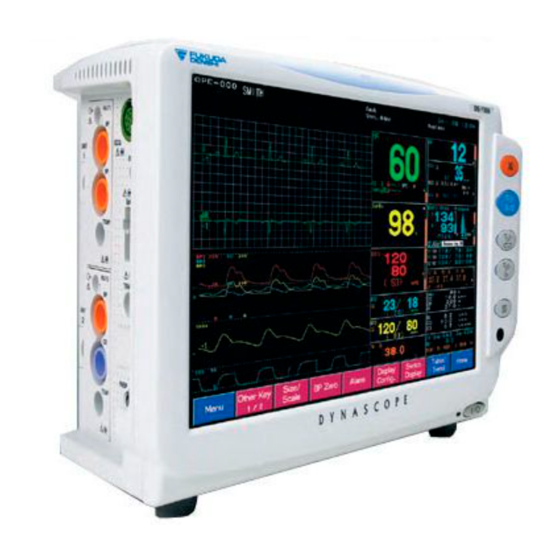
Chapter 1 General Description This chapter explains the general description of this equipment. ・・・・・・・・・・・・・・・・・・・・・・・・・・・・・ General Description Combination of Option Unit and Measurement ・・・・・・・・・・・・・・・・・・・・・・・・・・・・・・・・・・・・ Parameter ・・・・・・・・・・・・・・・・・・・・・・・・・・・・・・・・・・・・・・ Features ・・・・・・・・・・・・・・・・・・・・・・・・・・・・ External Appearance ・・・・・・・・・・・・・・・・・・・・・・・・・・ DS-7000 Main Unit ・・・・・・・・・・・・・ HU-71/HU-72/HU-73 Option Unit ・・・ MGU-701/MGU-702 Multigas Unit (Optional) -... - Page 42 General Description The DS-7000 is a patient monitor with a 12.1-inch color LCD which measures ECG, heart rate, non-invasive blood pressure (NIBP), pulse rate, arterial oxygen saturation (SpO ), pulse wave, temperature, blood pressure, cardiac output. By using the built-in 3ch recorder, waveforms, list data, and trend data can be output to the recorder.
- Page 43 Combination of Option Unit and Measurement Parameter The following 3 types of option unit (maximum of 2 units) can be attached to the DS-7000 simultaneously. (However, only one unit for the HU-73.) 【Lineup of Option Unit】 Measurement Parameter Model Type TEMP Cardiac Output HU-71...
- Page 44 Features The DS-7000 is a compact and lightweight patient monitor all-in-one type, which consists of a display part, recording part, and measurement part. On the 12.1-inch color LCD, a maximum of 12 waveforms can be displayed. The numeric data display can be enlarged for easier view. List data, trend data, and ventilator data can also be displayed.
- Page 45 External Appearance DS-7000 Main Unit Weight: 9kg HU-71/HU-72/HU-73 Option Unit The illustration is HU-71. Weight: 180g -...
- Page 46 MGU-701/MGU-702 Multigas Unit (Optional) Weight: 1.8kg -...
-
Page 47: Specification
Chapter 2 Specification ・・・・・・・・・・・・・・・・・・・・・・ Specification / Performance Specification ・・・・・・・・・・・・・・・・・・・・・・・・・・・・・・・・・・ Performance ・・・・・・・・・・・・・・・・・・・・・・・・・・・・・・・・・・ -... - Page 48 S pecification / Performance This section states the specification and performance of the DS-7000. S pecification Size/Weight DS-7000/DS-7000M 324(W) × 179(D) × 260(H) mm (not including the protrusion) Size Weight 9.0 kg HU-71/HU-72/HU-73 (Option Unit) 37(W) × 99(H) × 90(D) mm (not including the protrusion) Size Weight 180 g...
- Page 49 Usable Life 6 years According to self-certification Refer to “10. Maintenance Periodic Replacement Parts” for parts requiring periodic replacement. P erformance Display Display Device 12.1 inch TFT Color LCD Resolution 1024×768 pixel Function Control Fixed Keys (5) + Touch Keys Waveform Trace Stationary Trace Sweep Speed...
- Page 50 Heart rate meter accuracy and response to irregular rhythm (IEC 60601-2-27: 2005 6.8.2 bb) 4)) 80bpm Ventricular Bigeminy : 80bpm 60bpm Slow Alternating Ventricular Bigeminy : 60bpm 120bpm Rapid Alternating Ventricular Bigeminy : 120bpm 90bpm Bidirectional Systoles : 90bpm Response time of heart rate meter to change in heart rate (IEC 60601-2-27: 2005 6.8.2 bb) 5)) HR changes from 80bpm to 120bpm : Range 4.8–6.1 sec.
- Page 51 Respiration Method Impedance Method Frequency Characteristic : 1.5Hz (adult, child) / 2.5Hz (neonate) Transient Characteristic Time Constant 1.5 sec. 100 μ A or lower Current Measurement Range 0, 4–150Bpm ± 3 Bpm Accuracy Base Impedance 500Ω–2kΩ Delta Impedance 0.2–3.0Ω or above Measurement Current Frequency 65kHz...
- Page 52 Blood Pressure : 5 μ V / V / mmHg Transducer Sensitivity Measurement Range : –50 to 300 mmHg/–6.6 to 40.0kPa Frequency Characteristic : DC–6Hz / 8Hz / 12Hz / 40Hz : ± 2% of full scale or within ± 1mmHg/0.1kPa Accuracy : Less than ±...
- Page 53 Sevoflurane 0.3 vol. % Desflurane 0.3 vol. % Mixed Gas Threshold : 0.2 vol. % + 10 % of total concentration Rise Time : CO 350msec 400msec 600msec Agents: 450msec Occlusion Clearing : Automatic Auto Zeroing : Occurs 30 to 60 minutes Duration: 3.0 to 7.0 seconds Manual user calibration not required Warm-up Time...
- Page 54 For Gas Mixtures of 2% Halothane Agents Agent Volume Change of CO +0.1 Halothane Enflurane +0.1 Isoflurane –0.1 Sevoflurane +0.1 Desflurane* +0.1 Helium –0.1 Ethanol Isopropanol +0.1 Acetone +0.1 Methane Metered dose inhaler propellant 80% Xenon Not intended for use with Xenon For Gas Mixtures of 2% Enflurane Agents Agent Volume...
- Page 55 For Gas Mixtures of 2% Sevoflurane Agents Agent Volume Change of CO Halothane +0.3 Enflurane +0.6 Isoflurane +0.2 Sevoflurane Desflurane* –0.2 Helium Ethanol +0.1 Isopropanol +0.1 Acetone +0.1 Methane Metered dose inhaler propellant +0.1 80% Xenon Not intended for use with Xenon For Gas Mixtures of 2% Desflurane Agents Agent Volume...
- Page 56 Other Interference Ether, cyclopropane and methoxyflurane are contraindicated for use with the multigas unit. The effect of ethyl alcohol and metabolic ketones and acetone are negligible. The multigas unit is not intended for monitoring gas mixtures containing W A R N I N G methoxyflurane or halogenated hydrocarbons not specifically listed as a monitored gas.
-
Page 57: Names Of Parts And Their Functions
Chapter 3 Names of Parts and Their Functions ・・・・・・・・・・・・・・ Names of Parts and Their Functions ・・・・・・・・・・・・・・・・・・・・・・・・・・・・・ DS-7000 Main Unit 【Front Side】 ・・・・・・・・・・・・・・・・・・・・・・・・・・・・・ 【Rear Side】 ・・・・・・・・・・・・・・・・・・・・・・・・・・・・・・ ・・・・・・・・・・・・・・・・・・・・・・・・・・・・・・・ 【Left Side】 ・・・・・・・・・・・・・・・・・・・・・・・・・・・・・ 【Right Side】 ・・・・・・・・・・・・・・・・・ HU-71/HU-72/HU-73 Option Unit 【Front Side】 ・・・・・・・・・・・・・・・・・・・・・・・・・・・・・ 【Rear Side】 ・・・・・・・・・・・・・・・・・・・・・・・・・・・・・・... -
Page 58: Names Of Parts And Their Functions
Names of Parts and Their Functions DS-7000 Main Unit 【Front Side】 Alarm Indicator LCD Touch Screen Lights when an alarm generates. Operation is performed using the Alarm Silence Key touch keys. Silences alarm sound. NIBP Start/Stop Key Starts/stops NIBP measurement. LED lights in green during measurement. -
Page 59: Rear Side
【Rear Side】 Serial Connector (COM1–COM4) Lead Check Terminal Connects the specified equipment. Used for checking ECG lead cable conduction. ORC Connector Connects the telemetry transmitter module, HLX-501, HLX-561. Option Unit Eject Lever Equipotential Ground Terminal Option Unit Fixing Screw Used for equipotential ground connection. -
Page 60: Right Side
NIBP Cuff Connector Connects the NIBP cuff. Do not connect unit or cable not authorized by Fukuda Denshi to any I/O connector. If done so by mistake, the device cannot deliver its maximum W A R N I N G performance and the connected units may be damaged, resulting in a safety hazard. -
Page 61: 71/Hu-72/Hu-73 Option Unit
HU-71/HU-72/HU-73 Option Unit 【Front Side】 Analog Output Connector Analog Output Outputs the BP HU-71 HU-72 Connector waveform. Outputs the BP waveform. BP Input Connector BP Input Connector Connects the BP Connects the BP interface cable. interface cable. Body Temperature Input Connector Connects the TEMP sensor cable. -
Page 62: Mgu-701/Mgu-702 Multigas Unit (Optional)
MGU-701/MGU-702 Multigas Unit (Optional) Air Inlet Air inlet for air calibration Inlet Connects the water trap and inhales the sampling gas. Position for the Water Trap (with reservoir) Removes the water inside the sampling tube connected to the patient. Multigas Unit Detach Button Press here when detaching the Sampling Gas Exhaust Outlet Multigas Unit from the DS-7000. -
Page 63: Connection With Other Devices
Connection with Other Devices Connection with a Slave Monitor A slave monitor can be connected to the DS-7000. The specified XGA slave monitor equipped with analog RGB interface can be connected. * Standard analog RGB video cable can be also used. As the picture resolution of the slave monitor will be the same as the DS-7000 touch panel display (XGA 1024 ×... -
Page 64: Telemetry Transmitter Module
Telemetry Transmitter Module The HLX-501/HLX-561 Telemetry Transmitter Module can be attached to the DS-7000. Use the OA0-23A Wire Adapter (optional accessory of HLX-501/HLX-561) to connect the HLX-501/HLX-561 to the ORC connector on the DS-7000. Then use the mounting plate to fix it on to the DS-7000. -
Page 65: Power Source And Ground Connection
Power Source and Ground Connection Connecting the Power Cable Connect the power supply cable provided to the power supply connector on the DS-7000. Connect the other end of the power cable to the hospital grade 3-way outlet with ground terminal. Power Supply Connector -... -
Page 66: To Turn On The Power Switch
To Turn On the Power Switch Turn ON the power switch of the DS-7000. The monitoring display will appear, and monitoring will start. The power supply LED on the front side of the main unit will light in green to indicate that the power is ON. -
Page 67: Spare Parts List
Chapter 4 Spare Parts List This spare part list describes the electrical parts and internal cables. ・・・・・・・・・・・・・・・・・・・・・・・・・・・・・・ DS-7000 Main Unit ・・・・・・・・・・・・・・・・・・・・・・・・ NIBP Module (NIBP-701) ・・・・・・・・・・・・・・・・・・・・・・・・ Option Unit (HU-71/72/73) ・・・・・・・・・・・・・・・・・・・・・ Multigas Unit (MGU-701/702) -... - Page 68 DS-7000 Main Unit The electrical spare parts of the main unit of DS-7000 block are as follows: Item Code Item Name Model Name Note - 9F0100090 Main CPU board PCB-7114SAS - 9F0100100 Sub CPU board PCB-7115SAS - 9F0100110 Analog board PCB-7101SAS -...
- Page 69 NIBP Module (NIBP-701) The NIBP module (NIBP-701) spare parts of DS-7000 are as follows: Item Code Item Name Model Name Note - 9F0055540 NIBP Module, Main board PCB-7096SAS - 9F0055550 NIBP Module, Panel board PCB-7097SAS - - 1M0015540 NIBP Pressure pump cable 6C0070960 NIBP Pressure pump RFP32B-05R...
- Page 70 Blank Page -...
-
Page 71: Software Upgrade
Chapter 5 Software Upgrade ・・・・・・・・・・・・・・・・・・・・・・・・・・・・・・・ Software Upgrade ・・・・・・・・・・・・・・・・・・・ Software Upgrade Verification -... - Page 72 Software Upgrade This paragraph explains how to perform the upgrade. In DS-7000, the upgrade is done via a Compact Flash card (hereafter, CF card). The upgrade of the DS-7000 main unit and NIBP module will be performed simultaneously. Turn the power OFF and insert the CF card in the card slot on the right side of the monitor. Turn the power ON and the upgrade will start automatically.
- Page 73 Once the “COMPLETE” message (bottom one) and the following messages are displayed on the screen, the upgrade is completed. 1. Turn the main power OFF 2. Remove the CF card (from card slot). Turn the power OFF and remove the CF card from the card slot.
- Page 74 Software Upgrade Verification Check the software version after the upgrade is completed. Press the following keys: Menu → Maintenance → Program Version . The software version of the DS-7000 will be displayed under the following: ・MAIN-CPU ・SUB-CPU ・NIBP Module Moreover, the boot version is displayed. Verify that the software version has been updated.
-
Page 75: Troubleshooting
Chapter 6 Troubleshooting ・・・・・・・・・・・・・・・・・・・・・・・・・・・・・・・ Power Supply ・・・・・・・・・・・・・・・・・・・・・・・・・・・・・・・・・・・・・ Backup ・・・・・・・・・・・・・・・・・・・・・・・・・・・・・・・・ Alarm Sound ・・・・・・・・・・・・・・・・・・・・・・・・・・・・・・・・・・・ Telemetry ・・・・・・・・・・・・・・・・・・・・・・・・・ Remote Control Unit ・・・・・・・・・・・・・・・・・・・・・・・・・・・・・・・・・・・・・・ Others ・・・・・・・・・・・・・・・・・・・・・・・・・・・・・・・・ Touch Panel ・・・・・・・・・・・・・・・・・・・・・・・・・・・・・・・・・・・・・・・ ・・・・・・・・・・・・・・・・・・・・・・・・・・・・・・・・・ Respiration ・・・・・・・・・・・・・・・・・・ Non-Invasive Blood Pressure ® ・・・・・・・・・ (Nellcor Model; DS-7000) 6-10 ® ・・・・・・・・ (Masimo Model; DS-7000M) 6-11 ・・・・・・・・・・・・・・・・・・・・・... -
Page 76: Power Supply
Power Supply The power of the DS-7000 does not turn ON. The power supply LED does not light. Cause : The power supply switch of the DS-7000 is not turned ON. Solution : Turn ON the power supply switch located on the front side of the DS-7000. In normal condition, the power supply LED will light in green. -
Page 77: Backup
Judged as NG if the value varies more than ±1.2V. Immediate correction must be performed as this may +12V 12.0V cause malfunction such as sound not generating from the speaker. Judged as NG if the value varies more than ±0.25V. Immediate correction must be performed as this may 5.0V cause malfunction such as sound not generating from... -
Page 78: Telemetry
: The data transmission with the telemetry transmitter has failed. Solution : Broken wire or a faulty telemetry transmitter can be considered. Contact service department of Fukuda Denshi. There is no reception at the telemetry center. Cause : The channel ID or group ID does not correspond with the telemetry receiver. -
Page 79: Touch Panel
: Due to scratch on the touch panel, or foreign substance getting into the touch panel attachment part, etc, the correct key area may not be properly detected. Solution : The touch panel needs to be replaced. Contact service department of Fukuda Denshi. A specific part on the touch panel does not function. Cause : The touch panel is damaged. - Page 80 Perform equipotential grounding with the peripheral devices using the equipotential ground terminal as necessary. Cause 2 : The electrode contact is poor. Electrical blanket or other noise source is near the patient. Solution : Improve the position of the electrode. ・Replace the lead cable if defective.
-
Page 81: Respiration
・Perform equipotential grounding with the peripheral devices using the equipotential ground terminal as necessary. ・If any noise source is near the patient, move it away from the patient as much as possible. Solution 2 : Attach the electrodes firmly. ・Replace the lead cable if defective. ・If any noise source is near the patient, move it away from the patient as much as possible. -
Page 82: Non-Invasive Blood Pressure
Non-Invasive Blood Pressure The cuff is not inflated although the pump is operating. Cause 1 : The air hose is not firmly connected, and the air is leaking. Solution : Check if the air hose is properly connected. Cause 2 : The cuff size does not match the selected patient type. - Page 83 Maintain the correct posture as much as possible during measurement. Make sure that the patient does not bend his arm or the hose is not bent during measurement. Monitor System error Code (E08-01 to E09-Y) Cause : System error occurred in the NIBP module due to the following cause: E08-01: Communication error with sub-CPU E08-02: Watchdog time out E08-03: Pressure offset error...
-
Page 84: Spo (Nellcor Model; Ds-7000)
® (Nellcor Model; DS-7000) The “Check SpO Sensor” message is displayed. Cause : The sensor is detached from the patient. Solution 1 : Check if the sensor is properly attached to the patient. Solution 2 : Check if the light emitting part and light receiving part of the sensor LED are aligned. The “Pulse Search”... - Page 85 The “SpO Sensor Defective” message is displayed. Cause : Sensor is defective. Solution : Replace the sensor. The “Disconnect” message is displayed. Cause : When the SpO relay cable is disconnected during SpO monitoring, this message will be displayed. Solution 1 : To cease monitoring, press the (Alarm Silence) key and silence the alarm.
-
Page 86: Invasive Blood Pressure
The “SpO Unit Error” message is displayed. Cause : There is a problem in the communication with the SpO measurement unit. Solution : A defective cable or faulty SpO unit can be considered. The “Disconnect” message is displayed. Cause : When the SpO relay cable is disconnected during SpO monitoring, this message will be displayed. -
Page 87: Cardiac Output
The “TEMP not connected” message is displayed. Cause : When the temperature sensor is disconnected during temperature monitoring, this message will be displayed. Solution 1 : To cease monitoring, press the (Alarm Silence) key to silence the alarm. Solution 2 : To continue monitoring, plug in the temperature sensor. This will clear the message and silence the alarm. - Page 88 The baseline of the thermodilution curve is moved to the minus side. The “Lower Fault” message is displayed on the monitor. Cause : The blood temperature has not returned to a stable condition after the measurement. Peak Point 30% of the peak value 30sec.
-
Page 89: Multigas Unit (Mgu-701/Mgu-702/Poet Iq)
The “Gas Unit Failure 1” message is displayed. Cause : The gas unit detected a hardware failure. Solution : Contact service department of Fukuda Denshi. The “Gas Unit Failure 3” message is displayed. Cause : The gas unit detected a hardware failure. -
Page 90: Ventilator
If the warm up does not complete within 30 minutes, check all the connected cables, sampling tubes, nasal cannula, and turn OFF and ON the power again. If the trouble persists, contact service department of Fukuda Denshi. The “O Sensor Failure” message is displayed. -
Page 91: Recorder
The “Vent. Offline” message is displayed. The ventilator screen is also displayed. Cause : Communication error has occurred due to the following cause. ・The power of the ventilator is turned OFF. ・The ventilator is in standby mode. ・The cable connecting the ventilator and DS-7000 is disconnected, or not securely connected. - Page 92 Blank Page -...
- Page 93 Chapter 7 Maintenance Replacing the Air Filter ・・・・・・・・・・・・・・・・・・・・・・ 7-22 DIP Switch / Rotary Switch Setup ・・・・・・・・・・・・・・・ ●Cleaning and Replacing the Air Filter DIP Switch Setup ・・・・・・・・・・・・・・・・・・・・・・・・・・・・ on the DS-7000 Main Unit ・・・・・・・・・・・・・・ 7-22 Rotary Switch Setup ・・・・・・・・・・・・・・・・・・・・・・・・・・ ●Cleaning and Replacing the Dust Filter Test Menu ・・・・・・・・・・・・・・・・・・・・・・・・・・・・・・・・・・・・...
-
Page 94: Dip Switch / Rotary Switch Setup
DIP Switch / Rotary Switch Setup In this section, the settings of the DIP switch and rotary switch are explained. DIP Switch Setup The DIP switch is located under the maintenance cover at the side of the monitor. SW No. Default Description (When ON) Memory test mode at startup: ON... -
Page 95: Test Menu
The adjustment result will be stored. Refer to the section on “Recorder Adjustment”. QRS Detect : If QRS detection is not correctly performed due to double trigger, etc., record Mode 1, Mode 2, Mode 3 waveforms and contact Fukuda Denshi. Dyna Alert : Analysis Information of Dyna Alert is displayed. -... - Page 96 NIBP Test : This is the test mode for the NIBP pump. A service tools is required to perform this test. *On this test mode, never press the START/STOP key when the cuff is connected to the patient. Log 1 Log 2 : Records the time and information at power ON/OFF, abnormal system restart, exceptional handling, etc.
-
Page 97: Details Of The Test Menu
Demo Start : This key will start the DEMO mode. The DEMO mode key will be displayed only when the rotary switch on the main body is set to "2". When the demonstration is finished, please make sure to turn off the power and return the rotary switch to "0". - Page 98 Remote Control Code (R.C. Code) Displays the reception status of the remote control (CF-700), which does not depend on the “Remote Control” settings under the “Initial Settings” menu. If the remote control is malfunctioning although the reception status displayed on this screen is normal, check the “Remote Control”...
-
Page 99: Video I/F
●Video I/F Touching the display panel will sequentially display the following patterns. “Black” → “White” → “Gray Scale (8 gradation)” → ”Burst” → “Red” → “Green” → “Blue” When all 7 patterns are displayed, Video I/F test is completed and returns to test menu. Blue ↑... -
Page 100: Touch Panel
●Touch Panel ○ Each time the touch panel is pressed, the coordinates and a marker “ + ” is displayed. If there is a big shift between the position pressed and the marker, perform the touch panel adjustment. Pressing the touch panel at any position for more than 3 seconds will return to the test menu screen. -
Page 101: Eeprom
●EEPROM Allows verification of the EEPROM data, where specified information of the equipment is stored. Page 1/2 will not be particularly used for maintenance. The DS-7000 stores the accumulative operating hours of the major modules, and this display allows the verification. (It is the same as the exchange part time screen under maintenance.) -... -
Page 102: Recorder Adjustment
●Recorder Adjustment 1) Paper Out Sensor and Mark Sensor Adjustment 1 Take out the paper from the recorder cassette. → Check that “No” is displayed. 2 Set the cassette. → Check that “Yes” is displayed. 3 Press the Paper Out Sensor Adjustment → Start key. →... - Page 103 2) Test Printing *This adjustment should be performed in room temperature. 1 Press the Print Test key. → Check that “Yes” is displayed. 2 Verify the printing result in accordance with the following judgment criteria. Printhead Voltage 1st Page Judgment Criteria There should be no patches inside the Printhead voltage blocks.
- Page 104 ・ All 6 patterns (blocks) should be ・ Intensity of the upper and ・ Intensity of the upper and correctly printed. lower part should be even. lower part should be even. (Printhead voltage test) ・ It should not be smudged. ・...
-
Page 105: Nibp Test
●NIBP Test The NIBP function is tested. Each test begins when the START/STOP key is pressed. When the ALL TEST START/STOP key is pressed, all the tests will be done automatically. A faulty NIBP module is to be considered if there is “NG" for result on the test display. Inflation Time The inflation performance of the NIBP pump is tested. -
Page 106: Cf Card
●CF Card By using a CF card, the data on this equipment can be stored, read, or copied. CF Card Format Formats the CF card so that it can be used on the DS-7000 series. A CF card formatted on a PC cannot be used on the DS-7000. C A U T I O N The CF card must be formatted on the DS-7000. -
Page 107: Module Installation
●Module Installation This is where you install the telemeter (HLX-501, HLX-561) software for the DS-7000. 1. Insert the CF card of the software upgrade of the module. 2. The current software version and the CF card version are displayed, then press the Start Install key to install the software. -
Page 108: Maintenance (Sub-Cpu)
●Maintenance (SUB-CPU) CPU A/D Item Verifies the data such as voltage and analog data read by the A/D converter, and checks if they are in the normal operating range. If “NG” is displayed, malfunction of the circuit can be considered. UNIT-VERSION Displays the version of the analog board, NIBP unit, SpO unit, option unit, software version,... -
Page 109: Qrs Detect
●QRS Detect This is the QRS Detect status display, for development use. ●Dyna Alert This is the status Dyna Alert display, for development use. ●Log 1 / Log 2 This is the LOG 1/2 status display, for development use. ●Log 2 (SUB-CPU) This is the LOG 2 (SUB-CPU) status display, for development use. -
Page 110: Storage
Storage This section describes about storing the equipment and recording paper. Storing the Device Store in a place where the device will not be exposed to splashing water. Store in a place where the device will not be adversely affected by atmospheric pressure, temperature, humidity, ventilation, sunlight, dust or atmosphere containing salt or sulfur. -
Page 111: Cleaning
Cleaning This section explains about the cleaning of the housing and display panel. Cleaning the Display Panel Since this equipment incorporates a touch screen, fingerprints and other stains are likely to appear on the display panel. Follow the procedure below to clean the display panel. Press the Menu Function... -
Page 112: Cleaning The Housing
Cleaning the Housing Clean the housing using tightly squeezed gauze or an absorbent cotton cloth dampened with alcohol or a neutral cleanser. Clean the equipment frequently so stains can be removed easily. To prevent injury, it is recommended to wear gloves when cleaning the equipment. -
Page 113: Cleaning And Disinfecting The Temperature Probe
Cleaning and Disinfecting the Temperature Probe Disinfect the temperature probe according to the guidelines provided with the product. When cleaning, follow the procedure below. (1) Wipe the probe using 70% isopropyl alcohol in cotton. (2) Dry it completely to air before use. Cleaning the Cardiac Output Relay Cable Disinfect the cardiac output relay cable according to the guidelines provided with the product. -
Page 114: Replacing The Air Filter
Replacing the Air Filter The cooling fan air filter on the DS-7000 and Multigas Unit is a consumable product. Continuous operation of the fan will cause the air filter to inhale unclean air inside the equipment, reduce the cooling effect, and may damage the inner parts. Clean the air filter, or replace it with a new air filter every 3 months. -
Page 115: Cleaning And Replacing The Dust Filter On The Mgu-701/Mgu-702 Multigas Unit
●Cleaning and Replacing the Dust Filter on the MGU-701/MGU-702 Multigas Unit Take off the dust filter from the Multigas Unit by sliding it to the right. Dust Filter Clean or replace the dust filter. To clean the dust filter, shake the dust off, or wash it off with neutral detergent. Re-insert the dust filter. -
Page 116: Replacing The Short-Term Backup Battery
Do not use it as a replacement battery. N O T E For some product, the battery is not installed at specified location and needs to be relocated when replacing. For additional components requirement for this procedure, contact Fukuda Denshi. -... -
Page 117: Disassembly And Assembly
●Disassembly and Assembly 1. Remove the NIBP unit (bottom) from the main body. Phillips screws M3 (x4) ・Take care when disconnecting the silicon tube, the speaker cable, and the NIBP cable. 2. Remove the battery unit. Phillips screws M3 ( × 2) ・Disconnect the short/long time backup connectors. - Page 118 4. Re-insert the battery unit with the new battery. Phillips screws M3 ( × 2) ・Reconnect the connectors for the short/long term backup battery. 5. Re-install the NIBP unit into the main body. Phillips screws M3 ( × 4) ・Reconnect the silicone tube, speaker cable and NIBP cable.
-
Page 119: Replacing The Nibp Unit
Replacing the NIBP Unit ●Service Life of the NIBP Unit The NIBP pump unit is able to perform approximately 100,000 measurements. If the unit is used for a longer period of time, air leakage may occur and proper function may not be achieved. Periodically replace the NIBP pump unit to maintain proper performance. -
Page 120: Replacing The Recorder Unit
Replacing the Recorder Unit ●Service Life of the Recorder Unit The recorder unit can be used for approximately 350 hours. If using the recorder over its service life, the print out will definitely become worse and the recorder will need to be replaced. ●Tools for Replacement ・Phillips Screwdriver (Large) ●Disassembly and Assembly... -
Page 121: Replacing The Co 2 Absorber (Mgu-701/702)
Replacing the CO Absorber (MGU-701/702) ●Service Life of the CO Absorber The CO absorber can be used for approximately 1 year. If the CO absorber is used over its service life, correct CO measurement may not be possible. Replace within 1 year. ●Tools for Replacement ・Phillips Screwdriver (Large) ●Disassembly and Assembly... -
Page 122: Replacing The O 2 Cell (Mgu-701 Only)
7. Re-install the rear panel from the multigas 8. Press the Menu → Maintenance → unit. Parts Usage Time keys and press the Reset (password “7000”) key for “CSI CO Absorber”. Press the Yes (Hold 3sec.) key to reset the usage for the CSI CO absorber. - Page 123 5. Re-connect the cable (Pay attention to 6. Re-install the shield. orientation). 7. Re-install the rear panel and perform 8. Press the Menu → Maintenance → calibration. Parts Usage Time keys and press the Reset (password “7000”) key for “CSI O Cell”.
-
Page 124: Maintenance Check
Maintenance Check Daily and Periodic Check This section explains daily check and periodic check of the device. About Maintenance Check Periodic inspection must be performed. When reusing the device, which was left unused for a while, always check that the device operates properly and safely before use. To ensure safety, reliability, and high performance, a “Daily Check”... -
Page 125: To Check The Periodic Replacement Period
●To Check the Periodic Replacement Period The usage duration for each “periodic replacement part” is displayed under Parts Usage Time . Use this information as an indication for the replacement period of each part. Press the Menu → Maintenance → Parts Usage Time keys. The usage hours, months, years, or number of measurements will be displayed for the respective parts. - Page 126 Daily Check List Inspected Date Inspected by Location Device Type (Main Unit) Serial No. Device Type (Option Unit) Serial No. Device Type (Multigas Unit) Serial No. Item Details Criteria Judgment Visually check the exterior for scratches, cracks, No abnormality should be found. □OK / □NG Appearance deformation, and rust.
-
Page 127: Periodic Check
Periodic Check ●Introduction The periodic maintenance check is intended to check the medical equipment used daily in a medical institution to prevent failures and accidents and to ensure safety and reliability. As these are general check procedures covering the whole monitoring equipment, perform the check procedure for the corresponded function of the equipment. -
Page 128: Periodic Check Item
●Periodic Check Item The periodic check items are as follows. Check Item External Appearance Power Supply Part Display / Control / Record Respiration Temperature Non-invasive Blood Pressure Arterial Oxygen Saturation (SpO Invasive Blood Pressure Cardiac Output (CO) Oxygen Gas Concentration (O External Output (Analog Output) Calibration Electrical Safety... - Page 129 Check Item Check Procedure Criteria 2. Power Supply Part Main power supply indicator Main Power Supply Connect the power cable to the outlet, should light when system Switch and turn ON/OFF the power switch. turned ON. Battery Charging Install the battery, turn ON/OFF, The charge indicator should Operation OFF/ON the power supply switch and...
- Page 130 Check Item Check Procedure Criteria 4. ECG Input Impedance* Measure input impedance with safety Should be 5MΩ or above. tester. Suppression With SG-2000, input 50Hz or 60Hz Should be 10mmp-p or below Characteristic of 20Vr.m.s. signal, and measure for standard sensitivity Common-Mode fluctuation of each lead.
- Page 131 Check Item Check Procedure Criteria 5. Respiration Respiration With comprehensive tester or reference The displayed amplitude Waveform Accuracy respiration signal generator, input should be within sinusoidal waveform of 0.5Hz with base 10mm±2mm. resistance of 1.5kΩ/1Ω change. Respiration Rate Input reference respiration signal to Error should be within Accuracy comprehensive tester or respiration...
- Page 132 Check Item Check Procedure Criteria 9. Invasive Blood Pressure BP Accuracy Input 0, 100, 200mmHg with Error should be within (full comprehensive tester, and measure scale, 300mmHg) ±2% or the error between the displayed value ±1mmHg whichever is larger. and input value. Pulse Detection Input 30, 120, 160bpm with Pulse rate error should be...
- Page 133 Check Item Check Procedure Reference 13. Calibration Touch Panel Perform calibration when the display Touch panel calibration value is is largely displaced. stored in the display unit. Analog If measurement error of ECG, BP, Calibration value of analog board TEMP, CO is too large, perform is stored in the CPU board.
- Page 134 Check Item Check Procedure Criteria 14. Electrical Safety Earth Leakage Measure the earth leakage current of Earth Leakage Current (NC) Current (NC) normal condition using a safety tester. Should be ≤0.1mA According to test procedure of IEC 60601-1 19. Earth Leakage Measure the earth leakage current of Earth Leakage Current Current (SFC)
- Page 135 Check Item Check Procedure Criteria Withstand Voltage Apply AC1500V for 1 minute between the Should withstand applied Test (B-d) exterior and applied part (B-d). voltage. Note: The voltage differs depending on the internal protective circuit composition of the equipment. According to test procedure of IEC 60601-1 20. -...
- Page 136 ●Periodic Check List Patient Monitor Periodic Check Report Check Date Periodic Check Contract Delivery Date Location □Yes □No Customer Code Month Check Model Name Serial No.: Product Code Next Check Date Requested Acceptance Date Item Check Item Judge Check Item Judge Check Item Judge...
- Page 137 Chapter 8 Calibration ・・・・・・・・・ Calibration of Multigas Unit (MGU-701) ・・・・・・・・・・・ To Display the GAS Calibration Screen ・・・・・・・・・・・・・・・・・・・・・・ Gas Calibration Procedure -...
-
Page 138: Maintenance
Calibration of Multigas Unit (MGU-701) The O calibration is required every time the O cell (MGU-701) is replaced. (Refer to “9. Maintenance”). To Display the GAS Calibration Screen Press the Menu → Maintenance → GAS Calibration keys. Gas Calibration Procedure Press the Start O Cal key. - Page 139 Connect the specified calibration gas cylinder to the multigas unit. When the preparation of the O calibration is completed, gain and O offset value will be displayed, and the message, “Start to supply calibration gas.” will be displayed. Supply the calibration gas, and press the OK key. To cancel the O calibration, press the Cancel key.
- Page 140 Adjust the O Offset. When the O gain adjustment is completed, the message, “Stop to supply calibration gas and open to air.” will be displayed. Stop supplying the calibration gas and press the OK key. To cancel the O calibration, press the Cancel key. The message, “Adjusting O offset.”...
-
Page 141: Calibration
The message, “Adjusting O gain.” will be displayed. To cancel the O calibration, press the Cancel key. If the O offset has been adjusted, it is necessary to readjust the O gain. C A U T I O N If the O offset adjustment was not necessary, then the O gain readjust screen will not be displayed. - Page 142 calibration process is completed. When the updating of O calibration data is completed, the message, “O calibration is completed.” will be displayed. Pressing the OK key will display the GAS calibration screen. -...
- Page 143 39-4, Hongo, 3-chome, Bunkyo-ku, Tokyo, Japan Phone:+81-3-3815-2121 Fax:+81-3-3814-1222 Printed in Japan 4R0100110 200805...
Need help?
Do you have a question about the DynaScope 7000 Series and is the answer not in the manual?
Questions and answers