Sign In
Upload
Manuals
Brands
Fukuda Denshi Manuals
Monitor
DynaScope 7000 Series
Fukuda Denshi DynaScope 7000 Series Manuals
Manuals and User Guides for Fukuda Denshi DynaScope 7000 Series. We have
3
Fukuda Denshi DynaScope 7000 Series manuals available for free PDF download: Operation Manual, Service Manual
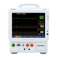
Fukuda Denshi DynaScope 7000 Series Operation Manual (475 pages)
Patient Monitor
Brand:
Fukuda Denshi
| Category:
Monitor
| Size: 8 MB
Table of Contents
Preface
3
Table of Contents
3
Composition of this Operation Manual
4
Safety Precautions
5
Labels Attached to the Unit
5
Measurement Unit for each Parameter
8
Graphic Symbols
11
Precautions for Safe Operation of Medical Electrical
12
Equipment
12
Precautions for Safe Operation of Medical Telemetry
13
Precautions about the Maintenance
14
Precautions about the Pacemaker
15
Non-Explosion Proof
15
Defibrillation Safety
15
Electrosurgery Safety
16
Precautions about Magnetic Resonance Imaging
16
Peripheral Devices
17
Precautions about the Fuse
17
Accessories and Optional Accessories
17
Precautions about the DS-7000
18
Precautions about the Wired Network System
28
Precautions about the Wireless Network System
31
Precautions about the Ventilator Monitoring
32
Precautions for Use of Spo 2 Sensor
32
Precautions for Masimo ® Model: DS-7000M
33
Precautions for Use of NIBP Cuff
33
Disposing of Equipment, Accessories, or Components
33
Precautions about Transportation
33
Precautions about RTC or Data Backup
33
To Prepare for Emergency Use
33
Electromagnetic Compatibility
34
Influence
34
EMC Guidance
34
Compliance to the Electromagnetic Emissions
35
Compliance to the Electromagnetic Immunity
35
Recommended Separation Distances between Portable and Mobile RF Communications Equipment and the DS-7000
37
Preface 1
39
General Description
40
Preface
40
Basic Operation
41
Vital Application
41
Initial Settings
123
Chapter 5 Admit / Discharge of a Patient
127
Admit / Discharge of a Patient
128
Admitting a Patient Name, Sex, and Age
129
Patient
129
Patient Name
129
Patient Classification
131
Pacemaker Usage
132
Patient Sex
132
Patient Age
133
Input Height/Weight/Bsa/Blood Type
134
To Enter the Patient Information from the Magnetic Card or Bar Code
135
To Enter the Patient Information from the Patient Data Server (DS-LANIII)
136
When Not Using the Magnetic Card
136
When Using the Patient Data Server and Magnetic Card (or Bar Code)
136
Discharging a Patient
138
Discharging Procedure
138
Erasing Name, Data, Etc
138
Alarm/Display Mode
139
Mode Selection
139
Monitoring Mode Selection
139
Display Modes
140
Alarm Modes
143
Suspend / Resume Monitoring
146
Suspend Monitoring
146
To Suspend Monitoring
146
To Resume Monitoring
147
Chapter 6 Parameter Setup
149
Setting the Monitoring Condition
151
To Display the Parameter Setup Menu
151
Zero Balance of Blood Pressure
152
Ecg
154
Waveform Size, Lead, and Baseline Position
154
Alarm
156
Arrhythmia Alarm
156
ECG Monitoring Condition Setup
157
Filter Mode Selection
157
Impedance Respiration Measurement
158
Pacemaker Usage
158
Pacemaker Pulse
159
QRS Pace Pulse Mask
160
AC Filter
161
ECG Drift Filter
161
Automatic Lead Switching
162
Synchronization Mark/Tone
162
Average Method
163
Noise Detection
163
PR Alarm Source
164
St/Vpc/Arrhy. Alarm Display
164
Display During Lead-OFF
165
ECG Waveform Display During Lead-OFF
165
ON/OFF of Parameter Display
166
Respiration
167
Waveform Size and Baseline Position
167
RR Alarm/Apnea Alarm
168
Respiration Monitoring Condition Setup
170
RR Alarm Source
170
RR Synchronization Mark
170
CVA Detection
171
Impedance Respiration Measurement
171
ON/OFF of Parameter Display
172
Invasive Blood Pressure (BP1 to BP6)
173
BP Label
174
When the BP Label Is CVP
175
When the BP Label Is IAP
175
When the BP Label Is ICP
175
PCWP Measurement
176
BP Scale
177
BP Alarm
178
Zero Balance
179
BP Monitoring Condition Setup
180
Filter Selection
180
Display Format of BP Numeric Data
181
Mean BP Waveform Display
181
PR Source (BP or Spo 2 )
182
Respiration Filter
182
Alarm During NIBP
183
BP Recording Scale
183
PR Alarm Source
183
ON/OFF of Parameter Display
184
Spo 2 (Nellcor ® Model; DS-7000)
185
Pulse Wave Size
186
Spo 2 Alarm
186
Spo 2 SEC Alarm Setup
187
PR Source (BP or Spo 2 )
188
Spo 2 Monitoring Condition Setup
188
Spo Alarm During NIBP Measurement
188
PR Alarm Source
189
Synchronization Mark/Tone
189
ON/OFF of Parameter Display
190
Spo 2 (Masimo ® Model; DS-7000M)
191
Pulse Wave Size
192
Spo 2 Alarm
192
PR Source (BP or Spo 2 )
193
Spo 2 Alarm During NIBP Measurement
193
Spo 2 Monitoring Condition Setup
193
Spo 2 Averaging
194
Synchronization Mark/Tone
194
PR Alarm Source
195
Pulse Wave Detection Sensitivity
195
FAST SAT Setup
196
PI Display
196
Signal IQ Wave Display
197
Spo 2 Low Perfusion Alarm
197
ON/OFF of Parameter Display
198
Non-Invasive Blood Pressure
199
NIBP Automatic Measurement
200
NIBP 1-Minute Interval Measurement
201
Continuous Measurement
202
NIBP Alarm
203
NIBP Measurement at Alarm Occurence
204
NIBP Monitoring Condition Setup
204
Patient Classification Selection
204
Quick Measurement
205
Dyna Alert Function
206
Oscillation Graph Display
207
Sight Inflation
207
Mean BP Value Display
208
Pulse Rate Display
208
End of Measurement Tone
209
Pump Setup
209
NIBP Data Erase Time
210
Start the Measurement Early
210
Displayed Time
211
Temperature (TEMP1 to TEMP3)
212
Temperature Label
212
T Display
213
Temperature Alarm
213
ON/OFF of Parameter Display
214
AWF Scale
215
AWP Scale
215
Ventilator
215
Tb (Blood Temperature)
216
Tb Alarm
216
STAT Mode / Index Display
217
Vigilance Data
217
Multigas Data
218
CO 2 Concentration Measurement Unit
220
MAC Value Display
220
MAC Value Calculation Constant
221
Gas Waveform Scale
222
Alarm Setup
223
CO Concentration Alarm
223
O (Nitrous Oxide) Alarm
223
Anesthetic Gas Alarm
225
MAC Value Alarm
225
Anesthetic Gas Label
226
Flow Rate
226
GAS Setup (MGU-701/MGU-702/Poet IQ)
226
ON/OFF of Gas Measurement
226
Wave Clip
226
Flow Rate
227
GAS Display During Undetected Breath
227
GAS Setup (MGU-801P/MGU-802/MGU-803)
227
ON/OFF of Gas Measurement
227
GAS Display During Undetected Breath
228
Manual Zero Calibration
228
Wave Clip
228
IRMA Probe)
229
Multigas Data
229
CO 2 Concentration Measurement Unit
231
MAC Value Display
231
MAC Value Calculation Constant
232
Gas Waveform Scale
233
Alarm Setup
234
CO Concentration Alarm
234
O (Nitrous Oxide) Alarm
234
O 2 Concentration Alarm
234
Anesthetic Gas Alarm
235
MAC Value Alarm
236
Anesthetic Gas Label
237
O 2 Concentration
238
ON/OFF of Waveform Clipping
238
ON/OFF of O Sensor
239
ON/OFF of Parameter Display
239
CO Concentration
241
O 2 Compensation
241
ON/OFF of Gas Measurement
241
Anesthetic Gas Compensation
242
Atmospheric Pressure Compensation
242
N 2 O Compensation
242
ON/OFF of Parameter Display
243
Radical-7 Data
244
Waveform Size
244
Chapter 7 Function
245
Display Priority Setup for
249
Display Setup for the Table
250
Parameter Setup for the Basic Table
251
The Description of the Display
252
Trend Display
254
Trend Display Setup
257
The Description of the Display
259
Display/Print
260
Recall
260
To Display the Recall Menu
260
Recall List Display
261
To Display and Record
262
To Set the Recall Condition
264
Label Setup
266
Start / Stop of Stopwatch
266
Stopwatch
266
ST Measurement ST Display, Alarm Setup, Etc
267
To Display the ST Measurement Menu
267
ST Display Lead Setup
268
To Set the Reference Waveform
269
ST Alarm Setup
270
Display/Print
271
ST Table
271
To Display the ST Table
271
ST Table Setup
272
The Description of the Display
272
Print Font Size for the bis Table
273
Display/Print
274
ST Trend
274
To Display the ST Trend
274
ST Trend Group Setup
277
The Description of the Display
278
Ocrg
279
To Display the Cardiac Output Menu
280
Message List
281
Cardiac Output Setup
282
To Measure the Cardiac Output
284
To Edit the Cardiac Output Data
285
Calculation Data
286
Calculation/Print
286
Hemodynamics
286
Input Hemodynamics Data
287
To Display the Hemodynamics Data
287
To Edit the Hemodynamics Data
289
BIS Table
290
Display/Print
290
To Display the bis Table
290
BIS Table Setup
291
The Description of the Display
291
Print Font Size for the bis Table
292
Display/Print
293
To Display the Vigilance Table
293
Vigilance Table
293
The Description of the Display
294
Vigilance Table Setup
295
Print Font Size for the Vigilance Table
296
Display/Print
297
NICO Table
297
To Display the NICO Table
297
NICO Table Setup
298
The Description of the Display
298
Print Font Size for the NICO Table
300
Display/Print
301
Respiration Table
301
To Display the Respiration Table
301
Respiration Table Setup
302
The Description of the Display
302
Print Font Size for the Respiration Table
303
P-V Loop
304
P-V, F-V Loop Display
304
Ventilator
304
F-V Loop
305
Displaying the Ventilator Measurement
307
Arrhythmia Analysis
308
Arrhythmia Definition
308
Arrhythmia Type
308
Definition, Etc
308
QRS Classification
308
To Set the Arrhythmia Alarm
309
To Perform Arrhythmia Learning
311
Other Monitor Display
312
Other Monitor Alarm Setup
313
Full Disclosure Waveform Recording
314
To Record the Full Disclosure Waveform Data
314
To Display the Full Disclosure Waveform
315
About the Waveform Display Duration
316
ECG Waveform Amplitude
317
To Change the ECG Waveform Size
317
To Search by Time
317
To Shift the Displayed Waveform
317
To Search by Admit/Discharge Date
318
To Search by Alarm
318
To Enlarge the Waveform
319
To Print the Waveform
319
Calculator
320
To Use the Calculator Function
320
Chapter 8 Installation
323
Precautions about the Operating Environment
324
Precautions for Installing the Equipment
324
Power Source and Ground Connection
325
Connecting the Option Unit
326
Connecting the Gas Unit (Optional)
327
Multigas Unit (MGU-701/MGU-702) Connection
327
Exhaust Line Connection (MGU-701/MGU-702)
328
Connection
329
Poet IQ 8500A Connection
329
Exhaust Line Connection (MGU-801P/MGU-802/MGU-803)
332
Gas Unit I/F (HPD-800) Connection
332
Gas Unit Selection
334
Connecting a Slave Monitor
335
Wireless Network Construction
336
Channel ID/Transmitting Waveform Setup
337
To Attach the Telemetry Module
337
DS-LANΙΙ Connection
340
Wired Network Construction
340
DS-LANΙΙΙ Connection
342
Ward Name/Or ID Setup
343
Ventilator Connection
346
Ventilator Selection
346
Connecting the Oximeter
347
Oximeter Connection
347
Oximeter Selection
348
BIS Monitor Connection
349
Serial Communication Setup
349
To Connect the bis Monitor
349
Connecting the NICO Monitor
350
NICO Monitor Connection
350
Serial Communication Setup
350
Fabius GS Anesthesia System Connection
351
Serial Communication Setup
351
Aepex Plus Monitoring System Connection
352
Serial Communication Setup
352
Radical-7 Pulse Oximeter Connection
353
Serial Communication Setup
353
Magnetic Card Reader Connection
354
To Connect the Magnetic Card Reader
354
Magnetic Card Reader Setup
355
To Read the Patient Data from Magnetic Card
358
Bar Code Reader Connection
359
To Connect the Bar Code Reader
359
Bar Code Reader Setup
360
To Read the Patient Data from Bar Code
360
Chapter 9 Initial Settings
361
About the Initial Settings Menu
362
About the Alarm Mode
363
Alarm Mode Setup
363
To Program the Alarm Mode
364
About the Display Mode
366
Display Mode Setup
366
To Program the Display Mode
367
User Keys
370
To Set the User Keys
371
Menu Key Layout
373
Erasing the Unnecessary Keys
374
Key Mask Setup
374
BP User Label
375
To Set the BP User Label
375
TEMP User Label
376
To Set the TEMP User Label
376
Measurement Unit
377
About the Remote Control Unit
378
Remote Control Setup
378
Remote Control Setup
379
Section Setup
381
Alarm Indicator
382
Alarm Level Setup
382
Flash Pattern Setup
383
Password
384
Operation at Discharge
385
About the Night Mode
387
Night Mode
387
To Set the Night Mode
389
Color of Function Keys
391
MAC Value Setup
392
Arrhythmia Analysis Setup
393
Magnetic Card Reader Setup
394
DS-LAN Setup
395
Source Setup
396
Chapter 10 Maintenance
397
Maintenance
397
Handling
398
Handling after Use
398
Handling the Touch Panel
398
Device/Recording Paper
399
Storage
399
Storing the Device
399
Storing the Recording Paper
399
Cleaning the Touch Panel
400
Cleaning and Disinfecting the Spo
401
Cleaning the Housing
401
Cleaning the NIBP Cuff and Air Hose
401
Disinfecting the Blood Pressure Transducers
401
Sensor
401
Cleaning and Sterilizing the Airway Adapter
402
Cleaning the Cardiac Output Relay Cable
402
Cleaning the DRYLINE™ Water Trap (MGU-801P/MGU-802/MGU-803)
402
Replacing the DRYLINE™ Water Trap (MGU-801P/MGU-802/MGU-803)
402
Replacing the Water Trap (MGU-701/MGU-702/Poet IQ)
402
Cleaning/Sterilizing the Airway Adapter
403
Replacing the Air Filter
403
Cleaning and Replacing the Fan Filter of the MGU-701/MGU-702 Multigas Unit
404
About Maintenance Check
405
Daily Check
405
Periodic Check
405
Periodic Replacement Parts
405
About the Maintenance of MGU-701/MGU-702/Poet IQ
406
About the Maintenance of MGU-801P/MGU-802/MGU-803
406
To Check the Software Version
409
Ecg
410
Troubleshooting
410
Invasive Blood Pressure
412
Respiration
412
Spo (Nellcor Model; DS-7000)
413
Spo (Masimo Model; DS-7000M)
414
Non-Invasive Blood Pressure
415
Temperature
415
Cardiac Output
416
Recorder
418
Wired Network (DS-LANII/DS-LANIII)
419
General
421
Remote Control Unit
421
Telemetry
421
Ventilator
422
Multigas Measurement
423
Multigas Measurement (MGU-801P/MGU-802/MGU-803)
424
Multigas Measurement
425
Multigas Measurement (IRMA Probe)
425
Oximeter
426
BIS Monitor
427
Magnetic Card Reader / Bar Code Reader
427
Chapter 11 Technical Information
429
Technical Information
429
Specification
430
Specification / Performance
430
Performance
431
Patient Admit / Discharge
442
Setup Item
442
Alarm Setup
443
Parameter Setup
446
Review Function Setup
449
Record Setup
453
Settings
453
Tone/Volume Setup
453
Display Configuration
454
Time/Date Setup
454
Color Setup
456
Display Setup
456
Other Monitor Alarm Setup
456
Initial Settings
457
Serial Communication Setup
457
User Key Setup
457
Key Mask Setup
458
Measurement Unit Setup
458
Menu Setup
458
Telemeter Setup
458
User Label
458
Alarm Indicator Setup
459
Discharge Setup
459
MAC Value Setup
459
Operating Room Setup
459
Password Setup
459
Remote Control Setup
459
Arrhythmia Analysis Setup
460
DS-LAN Setup
460
Magnetic Card Reader Setup
460
Source Setup
460
Alarm Mode Setup
461
COM1 Connector
464
COM2 Connector
464
COM3 Connector
464
External Connection
464
RS-232C Connector Output Signal
464
COM4 Connector
465
Chapter 12 Accessories
467
Accessories
467
Accessories
468
ECG, Impedance Respiration Measurement
469
Invasive Blood Pressure Measurement
469
Optional Accessories
469
Non-Invasive Blood Pressure Measurement
470
Spo 2 Measurement
470
Spo Measurement (Nellcor Model: DS-7000)
470
Temperature Measurement
470
Cardiac Output Measurement
471
Multigas Concentration Measurement
471
Multigas Concentration Measurement (ARTEMA Model)
471
Multigas Measurement
472
Multigas Measurement (RESPIRONICS ® Capnostat 5)
472
Advertisement
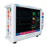
Fukuda Denshi DynaScope 7000 Series Operation Manual (177 pages)
Bedside Monitor
Brand:
Fukuda Denshi
| Category:
Medical Equipment
| Size: 9 MB
Table of Contents
Preface
3
Table of Contents
3
Composition of this Operation Manual
4
Safety Precautions
5
Labels Attached to the Unit
5
Graphic Symbols
10
Precautions for Safe Operation of Medical Electrical
13
Equipment
13
Precautions for Safe Operation of Medical Telemetry·XII
14
Precautions about the Maintenance
15
Precautions about the Pacemaker
15
Non-Explosion Proof
16
Defibrillation Safety
16
Electrosurgery Safety
16
Precautions about Magnetic Resonance Imaging
17
Precautions about Connections to Peripheral Devicesxv
17
Precautions about the Fuse
17
Accessories and Optional Accessories
17
Precautions about the DS-7200 System
18
Precautions about the Wired Network System
29
Precautions about the Wireless Network System
32
Precautions for Use of the Bidirectional Wireless
33
Communications (TCON)
33
Precautions about the Ventilator Monitoring
35
Precautions for Use of Spo 2 Sensor
37
Precautions for Masimo ® Model: DS-7210M
37
Precautions for Use of NIBP Cuff
37
Disposing of Equipment, Accessories, or Components
37
Precautions about Transportation
37
Precautions about RTC or Data Backup
37
Precautions for Use of Lithium-Ion Battery Pack
38
To Prepare for Emergency Use
39
Electromagnetic Compatibility
40
Influence
40
EMC Guidance
40
Compliance to the Electromagnetic Emissions
41
Compliance to the Electromagnetic Immunity
41
Compliance to the Electromagnetic Immunity (2)Xl
42
Recommended Separation Distances between Portable and Mobile RF Communications Equipment and the DS-7200 System
43
Preface 1
45
General Description
46
Preface
46
Basic Operation
47
Vital Application
47
Monitoring Setup
48
Admit / Discharge of a Patient
49
Parameter Setup
49
Function
50
System Configuration
104
Chapter 10 Maintenance
107
After Use / Display Panel
108
Handling
108
Handling after Use
108
Handling the Display Panel
108
Device / Recording Paper
109
Storage
109
Storing the Device
109
Storing the Recording Paper
109
Cleaning the Display Panel
110
Cleaning and Disinfecting the Spo Sensor
111
Cleaning the Cardiac Output Relay Cable
111
Cleaning the ECG Lead Cable, Relay Cable
111
Cleaning the Housing
111
Cleaning/Disinfecting the Temperature Probe
111
Disinfecting the Blood Pressure Transducers
111
Cleaning and Sterilizing the Airway Adapter
112
Battery
113
Handling the Battery
113
Handling the Battery Pack
113
Storing the Battery
113
About the Maintenance Check
114
Daily and Periodic Check
114
Daily Check
114
Maintenance Check
114
Periodic Check
114
Periodic Replacement Parts
114
Installation
116
Software Version
117
Ecg
118
Troubleshooting
118
Respiration
120
Invasive Blood Pressure
121
Spo (Nellcor Model: DS-7210)
121
Spo (Masimo Model: DS-7210M)
122
Non-Invasive Blood Pressure
123
Temperature
124
Cardiac Output
125
CO 2 Concentration (Option Unit: MGU-722)
127
CO 2 Concentration (Option Unit: MGU-721)
128
Wired Network (DS-LAN ΙΙ/ DS-LAN ΙΙΙ)
128
Remote Control Unit
130
Tcon
130
Telemetry
130
General
131
Battery
133
Ventilator
134
Oximeter
135
BIS Monitor
136
Recorder
136
Laser Printer
137
Chapter 11 Technical Information
139
Technical Information
139
Specification
140
Specification / Performance
140
Performance
141
COM1 Connector
146
COM2 Connector
146
COM3 Connector
146
External Connection
146
RS-232C Connector Output Signal
146
ECG Analog Output Connector
147
Status I/O Signal (Status ΙΙ Connector)
147
IBP Analog Output Connector
148
Patient Admit / Discharge
149
Setup Item
149
Alarm Setup
150
Parameter Setup
152
Review Function Setup
154
Display Configuration
157
System Configuration Setup
157
Tone/Volume Setup
157
System Configuration Menu
160
Hospital Setup
162
Monitor Setup
164
Alarm Mode Setup
167
Accessories
169
Accessories
170
ECG, Impedance Respiration Measurement
171
Invasive Blood Pressure Measurement
171
Optional Accessories
171
Non-Invasive Blood Pressure Measurement
172
Spo 2 2 Measurement (Masimo ® Type: DS-7210M)
172
Spo Measurement (Nellcor Type: DS-7210)
172
Temperature Measurement
172
CAPNOSTAT ® 5 CO 2 Sensor)
175
CO 2 Concentration Measurement (MGU-722)
175
Concentration Measurement
175
Others
175
Fukuda Denshi DynaScope 7000 Series Service Manual (143 pages)
Patient Monitor
Brand:
Fukuda Denshi
| Category:
Medical Equipment
| Size: 5 MB
Table of Contents
Preface
5
Table of Contents
5
Safety Precautions
6
Labels Attached to the Unit
6
Measurement Unit for each Parameter
9
Graphic Symbols
12
Precautions for Safe Operation of Medical Electrical Equipment
13
Precautions for Safe Operation of Medical Telemetry
14
Precautions about the Maintenance
15
Precautions about the Pacemaker
16
Non-Explosion Proof
16
Defibrillation Safety
16
Electrosurgery Safety
17
Precautions about Magnetic Resonance Imaging
17
Precautions about Connections to Peripheral Devices
18
Precautions about the Fuse
18
Accessories and Optional Accessories
18
Precautions about the DS-7000
19
Precautions about the Wired Network System (DS-LAN ΙΙ)
26
Precautions about the Wireless Network System
28
Precautions about the Ventilator Monitoring
29
Precautions for Use of Spo Sensor
29
Precautions for Masimo Model: DS-7000M
30
Precautions for Use of NIBP Cuff
30
Disposing of Equipment, Accessories, or Components
30
Precautions about Transportation
30
Precautions about RTC or Data Backup
30
To Prepare for Emergency Use
30
Electromagnetic Compatibility
31
Precautions for Safe Operation under Electromagnetic Influence
31
EMC Guidance
31
Compliance to the Electromagnetic Emissions
32
Compliance to the Electromagnetic Immunity
32
Compliance to the Electromagnetic Immunity
33
Recommended Separation Distances between Portable and Mobile RF Communications Equipment and the DS-7000
34
Table of Contents
35
Preface
36
General Description
41
Specification
47
Chapter 3 Names of Parts and Their Functions
57
Names of Parts and Their Functions
57
DS-7000 Main Unit
58
Front Side
58
Names of Parts and Their Functions
58
Left Side
59
Rear Side
59
Right Side
60
71/HU-72/HU-73 Option Unit
61
Front Side
61
Rear Side
61
MGU-701/MGU-702 Multigas Unit (Optional)
62
Connection with a Slave Monitor
63
Connection with Other Devices
63
Ds-Lanιι
64
Serial Connector
64
Telemetry Transmitter Module
64
Connecting the Power Cable
65
Power Source and Ground Connection
65
To Turn on the Power Switch
66
Spare Parts List
67
Software Upgrade
71
Chapter 6 Troubleshooting
75
Troubleshooting
75
Power Supply
76
Alarm Sound
77
Backup
77
Others
78
Remote Control Unit
78
Telemetry
78
Ecg
79
Touch Panel
79
Respiration
81
Non-Invasive Blood Pressure
82
Spo (Masimo Model; DS-7000M)
84
Spo (Nellcor Model; DS-7000)
84
Invasive Blood Pressure
86
Temperature
86
Cardiac Output
87
Multigas Unit (MGU-701/MGU-702/Poet IQ)
89
Ventilator
90
Analog Output
91
Recorder
91
Chapter 7 Maintenance
93
DIP Switch / Rotary Switch Setup
94
DIP Switch Setup
94
Rotary Switch Setup
94
Test Menu
95
Test Menu Items
95
To Display the Test Menu
95
Details of the Test Menu
97
Maintenance
97
Video I/F
99
Touch Panel
100
Touch Panel Adjustment
100
Eeprom
101
Recorder Adjustment
102
NIBP Test
105
CF Card
106
Module Installation
107
RTC Setup
107
Maintenance (SUB-CPU)
108
Dyna Alert
109
Log 1 / Log
109
Log 2 (SUB-CPU)
109
QRS Detect
109
SUB-CPU Test
109
About Handling the Display Panel
110
Storage
110
Storing the Device
110
Storing the Recording Paper
110
Cleaning
111
Cleaning the Display Panel
111
Cleaning the Housing
112
Cleaning the NIBP Cuff and Air Hose
112
Disinfecting the Blood Pressure Transducers
112
Cleaning and Disinfecting the Temperature Probe
113
Cleaning and Sterilizing the Airway Adapter
113
Cleaning the Cardiac Output Relay Cable
113
Replacing the Water Trap (MGU-701/MGU-702/Poet IQ)
113
Cleaning and Replacing the Air Filter on the DS-7000 Main Unit
114
Replacing the Air Filter
114
Cleaning and Replacing the Dust Filter on the MGU-701/MGU-702 Multigas Unit
115
Replacing the Short-Term Backup Battery
116
Service Life of the Short-Term Backup Battery
116
Tools for Replacement
116
Disassembly and Assembly
117
Disassembly and Assembly
119
Replacing the NIBP Unit
119
Service Life of the NIBP Unit
119
Tools for Replacement
119
Disassembly and Assembly
120
Replacing the Recorder Unit
120
Service Life of the Recorder Unit
120
Tools for Replacement
120
Disassembly and Assembly
121
Replacing the CO 2 Absorber (MGU-701/702)
121
Tools for Replacement
121
Disassembly and Assembly
122
Replacing the O 2 Cell (MGU-701 Only)
122
Tools for Replacement
122
About Maintenance Check
124
Daily and Periodic Check
124
Daily Check
124
Maintenance Check
124
Periodic Check
124
Periodic Replacement Period for each Part
124
About the Maintenance of MGU-701/MGU-702/Poet IQ
125
To Check the Periodic Replacement Period
125
Introduction
127
Periodic Check
127
Service Tools/Measurement Device
127
Periodic Check Item
128
Periodic Check Procedure
128
Maintenance
138
Calibration
141
Advertisement
Advertisement
Related Products
Fukuda Denshi Dynascope 7100
Fukuda Denshi Dynascope 8000 Series
Fukuda Denshi CC-82
Fukuda Denshi CC-83
Fukuda Denshi DS-7700
Fukuda Denshi DSC-8510
Fukuda Denshi DSC-8530
Fukuda Denshi Dyna Scope 7700 Series
Fukuda Denshi DynaScope DS-7000
Fukuda Denshi Categories
Medical Equipment
Transmitter
Monitor
Measuring Instruments
Control Unit
More Fukuda Denshi Manuals
Login
Sign In
OR
Sign in with Facebook
Sign in with Google
Upload manual
Upload from disk
Upload from URL