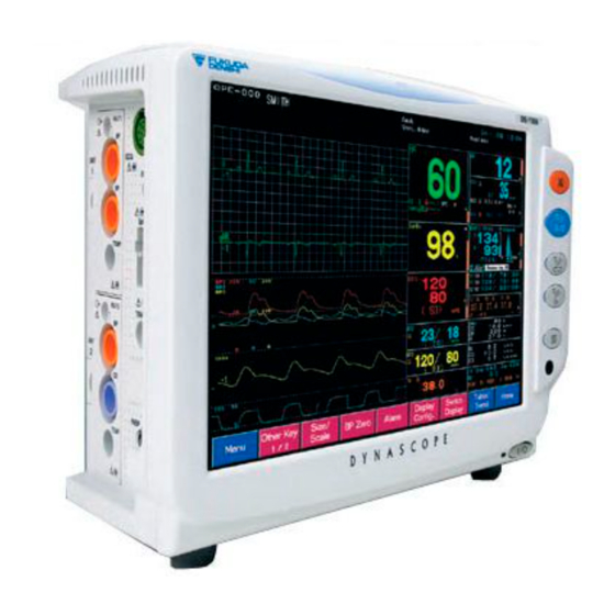
Fukuda Denshi DynaScope 7000 Series Operation Manual
Patient monitor
Hide thumbs
Also See for DynaScope 7000 Series:
- Service manual (143 pages) ,
- Operation manual (177 pages)

Related Manuals for Fukuda Denshi DynaScope 7000 Series


Summary of Contents for Fukuda Denshi DynaScope 7000 Series
- Page 1 DynaScope 7000 Series Patient Monitor DS-7000 System Ver.06 Operation Manual 《 Monitoring Operation 》 0086...
- Page 2 • The company and product names used in this manual are trademarks or registered trademarks. • If this manual has pages missing or out of order, contact Fukuda Denshi for replacement. • Only physician or persons instructed by physicians are allowed to use the equipment.
-
Page 3: Table Of Contents
Preface Thank you for purchasing this product. Before using this product, read the following precautions to make sure the product is used correctly and safely. Composition of This Operation Manual························· ii Safety Precautions ························································· iii Labels Attached to the Unit ··········································iii Measurement Unit for Each Parameter·······················... -
Page 4: Composition Of This Operation Manual
Composition of This Operation Manual The DS-7000 Operation Manual is composed of the following 2 sections. <<General Description>> This section is composed of the chapters stating the general description of the device and basic operation procedure. 1. General Description Describes the outline of this equipment. 2. -
Page 5: Safety Precautions
Safety Precautions Read the “Safety Precautions” thoroughly before use to ensure correct and safe use of the product. Be sure to follow the precautions indicated below, as these are important messages related to safety. Failure to follow this message may cause immediate threat of death or serious D A N G E R injury, or complete failure of the equipment. - Page 6 DS-7000 Patient Monitor DANGER Risk of explosion if used in the presence of flammable anesthetics. CAUTION Before connecting, read instruction manual. CAUTION To reduce the risk of electric shock, do not remove the cover. Refer servicing to qualified service personnel. HU-71/HU-72/HU-73 Option Unit DANGER Risk of explosion if used in the presence of flammable anesthetics.
- Page 7 MGU-701/MGU-702 Multigas Unit DANGER Risk of explosion if used in the presence of flammable anesthetics. CAUTION Before connecting, read instruction manual. CAUTION To reduce the risk of electric shock, do not remove the cover. Refer servicing to qualified service personnel. <MGU-701>...
-
Page 8: Measurement Unit For Each Parameter
Measurement Unit for Each Parameter The measurement units for this equipment are as follows. Detail Parameter Display Unit Default (beats per minute) Invasive Blood Pressure PR-IBP Heart Rate / Pulse (beats per minute) Rate PR-SpO (beats per minute) Non-Invasive Blood PR-NIBP Pressure (beats per minute) - Page 9 Detail Parameter Display Unit Default Mixed Venous Oxygen Saturation Central Venous Oxygen ScvO Saturation Arterial Oxygen Saturation Oxygen Uptake Index Oxygen Transport mL/minute Oxygen Consumption mL/minute Stroke Volume Stroke Volume SV-STAT (STAT Mode) Stroke Volume Index mL/m Stroke Volume Index SVI-STAT mL/m (STAT Mode)
- Page 10 Detail Parameter Display Unit Default Cardiac Output L/min (Average Mode) Cardiac Index L/min/m Cardiac Output (Fast Mode) CO-F L/min Carbon Dioxide Emission mL/min Minute Ventilation L/min Alveolar Minute Ventilation MVAL L/min Expiratory Tidal Volume TV-E Inspiratory Tidal Volume TV-I Peak Inspiratory Pressure Mean Airway Pressure Peak End Expiratory PEEP...
-
Page 11: Graphic Symbols
Graphic Symbols The following symbols are used for this equipment. DS-7000 Main Unit Symbol Description Caution; refer to accompanying documents Indicates the need to refer to related accompanying documents before operation. Potential Equalization Terminal Indicates the terminal to equalize the potential difference when interconnecting the devices. -
Page 12: Precautions For Safe Operation Of Medical Electrical
Keep the unit clean to ensure proper operation of the next use. If the equipment is damaged and in need of repair, user should not attempt service. Label the unit “OUT OF ORDER” and contact Fukuda Denshi. Do not remodel the equipment. -
Page 13: Precautions For Safe Operation Of Medical Telemetry
When interference or breakdown occurs in telemetry communication, the user is required to inform the zone manager and the overall manager of the problems. The zone manager and overall manager are to deal with the problem properly and/or contact their nearest Fukuda Denshi representative for service. -
Page 14: Precautions About The Maintenance
Maintenance, Modifications, and Repairs Fukuda Denshi is liable for the safety, reliability, and performance of its equipment only if; Maintenance, modifications, and repairs are carried out by authorized personnel. Components are used in accordance with Fukuda Denshi operating instructions. -
Page 15: Precautions About The Pacemaker
If such event occurs, please disconnect the cardiac monitoring and diagnostic equipment, or follow the procedures described in the operation manual of the pacemaker. (For more details, contact FUKUDA DENSHI personnel, your institution’s professionals, or your pacemaker distributors.) Reference W A R N I N G “Minute Ventilation Rate-Adaptive Pacemakers”... -
Page 16: Electrosurgery Safety
Electrosurgery Safety The monitoring system contains protection against interference generated by electrosurgical instruments. However, operating conditions, surgery site with respect to the location of ECG electrodes, or the type of instrument used, may cause noise on the ECG. The noise is generated at the tip of an electrical knife and is difficult to completely eliminate because of the frequency components of the ECG. -
Page 17: Peripheral Devices
Fukuda Denshi. It is the user’s responsibility to contact Fukuda Denshi to determine the compatibility and warranty status of any connection made to another manufacturer’s equipment. -
Page 18: Precautions About The Ds-7000
The DS-7000 is not intended for use with flammable anesthetic agents. Do not connect unit or cable not authorized by Fukuda Denshi to any I/O connector. If done so by mistake, the DS-7000 cannot deliver its maximum performance and the connected units may be damaged, resulting in a safety hazard. - Page 19 When using the airway adapter, always consider the circumference of the intubation tube. If inappropriate airway adapter is used for a patient with low ventilation, CO may mix in to the inspired air resulting in incorrect measurement, or apnea detection may become difficult. When the multigas unit (MGU-701/MGU-702/Poet IQ/MGU-801P/ MGU-802/ MGU-803) is used, the sampling line may get clogged by internal condensation.
- Page 20 The HR/PR alarm will not be generated unless the numeric data box corresponded to the selected HR/PR alarm source is displayed. When HR/PR alarm source selection is changed, be sure to display the numeric data box corresponding to the selected HR/PR source. The RR and apnea alarm will not be generated unless the numeric data box corresponded to the selected RR source is displayed.
- Page 21 Systems This equipment is intended to be used for only one patient. The installation of this equipment should be performed by our service representative or a person who is well acquainted with this equipment. The internal switch setting will be performed by our service representative.
- Page 22 When arrhythmia is present, HR measurement accuracy may be degraded. Select the appropriate lead for ECG1, 2 to be used for arrhythmia detection, telemeter, central monitor transmission, and recording. The selected lead for ECG l, 2 will be used for recall waveform and recording waveform as well as for arrhythmia analysis.
- Page 23 When not performing the measurement, unplug the relay cable and sensor from the SpO connector. Otherwise, the measurement data may be erroneously displayed by the ambient light. The DS-100A is intended for use on finger of adults weighing over 40 kg (approximate).
- Page 24 BP Monitoring When the main power is turned ON, the BP value will not be displayed until zero balance is performed. However, if the power is turned ON within 30 seconds from power OFF, the previous zero balance information is retained and the BP value will be displayed. Each time the blood pressure transducer or tubing is replaced, the zero balance procedure is required to ensure accurate measurements.
- Page 25 The accuracy of MGU-801P/MGU-802/MGU-803 may be affected at extreme temperatures. Do not store them at extreme temperature. Temperatures exceeding specified storage temperatures (-10 to 60°C) could damage the units. After the MGU-801P/MGU-802/MGU-803 is stored in low temperature, when turning on the device, it may require additional warm-up time. ®...
- Page 26 When the waveform and numeric data display for the gas module is set to OFF, the respiration rate measured by the gas module will not be displayed. If “Save Data to Table” is set to OFF on the alarm setup menu, data at alarm occurrence will not be stored in the table.
- Page 27 For MGU-701/MGU-702/Poet IQ, do not sterilize the airway adapter using autoclave methods. For MGU-701/MGU-702/Poet IQ, do not reuse / re-sterilize the disposable airway adapter. For MGU-701/MGU-702/Poet IQ, water traps are single use only. Do not attempt to drain the water trap when full. For MGU-801P/MGU-802/MGU-803, do not use other than specified cleaning methods for the water trap.
-
Page 28: Precautions About The Wired Network System
Precautions about the Wired Network System (DS-LAN II/DS-LAN III) Do not connect unspecified device to a wired network. Do not mix devices with DS-LANII and DS-LANIII setting in the same wired network. The network may cease and proper monitoring may not be possible. - Page 29 If using a HUB for the DS-LAN III network construction, make sure to use a switching HUB recommended by Fukuda Denshi. The displayable waveform, numeric data, and alarm will differ depending on the central monitor model type. Refer also to the operation manual for the respective central monitor.
- Page 30 There are following restrictions when recording the DS-7000 data on the central monitor recorder or the AU-5500N 8ch Recorder. Only manual recording, alarm recording, periodic recording, and recall recording can be performed on the AU-5500N. When a parameter is not measured, the waveform for that parameter will not be recorded, and measurement data will be recorded as “−...
-
Page 31: Precautions About The Wireless Network System
Precautions about the Wireless Network System When monitoring a patient with wireless telemetry, make sure the patient D A N G E R data is properly received at the central monitor. Pay special attention if the channel ID at the bedside monitor is changed. A password can be set to access the channel ID setup menu to allow only the telemetry channel administrator to change the channel ID. -
Page 32: Precautions About The Ventilator Monitoring
In SpO monitoring, always use the sensor/relay cable specified by Fukuda Denshi. If any other sensor/relay cable is used, a high temperature D A N G E R rise of the sensor may place the patient in danger of burns. -
Page 33: Precautions For Masimo ® Model: Ds-7000M
DS-7000 is turned off, this clock is backed up by a lithium primary battery. If incorrect time is displayed when turning on the power, a low battery may be the cause. In such case, contact Fukuda Denshi service representative for replacing the battery. -
Page 34: Electromagnetic Compatibility
Electromagnetic Compatibility The performance of this device under electromagnetic environment complies with EN 60601-1-2 (2007). Precautions for Safe Operation under Electromagnetic Influence If any sorts of electromagnetic wave, magnetic field, or static electricity exist around the device, noise interference or malfunction of the device may occur. If any unintended malfunction or noise occurs during monitoring, check the magnetic influence and take appropriate countermeasures. -
Page 35: Compliance To The Electromagnetic Emissions
●Compliance to the Electromagnetic Emissions The DS-7000 is tested under the following electromagnetic environment. Electromagnetic Environment – Guidance Emissions Test Compliance The DS-7000 is intended for use in the electromagnetic environment specified below.) The equipment uses RF energy that is necessary for the internal RF Emissions functioning of the equipment itself. - Page 36 ●Compliance to the Electromagnetic Immunity (2) The DS-7000 is tested under the following electromagnetic environment. Electromagnetic Environment - Guidance IEC60601-1-2 Compliance Immunity Test The DS-7000 is intended for use in the Test Level Level electromagnetic environment specified below.) Portable and mobile RF communications equipment should be used no closer to any part of the DS-7000, including cables, than the recommended separation distance calculated...
-
Page 37: Recommended Separation Distances Between Portable And Mobile Rf Communications Equipment And The Ds-7000
●Recommended Separation Distances between Portable and Mobile RF Communications Equipment and the DS-7000 The DS-7000 is intended for use in an environment in which radiated RF disturbances are controlled. The electromagnetic interference can be prevented by maintaining a minimum distance between portable and mobile RF communications equipment (transmitters) and the DS-7000 as recommended below, according to the maximum output power of the communications equipment. - Page 38 Blank Page xxxvi...
- Page 39 Contents Preface 1. General Description Describes the outline of this equipment. 2. Basic Operation Describes the basic operation for monitoring. 3. Vital Application Describes the procedure for vital application, etc. Describes the procedures to set the monitor 4. Monitoring Setup according to the monitoring purpose.
-
Page 40: Preface
Preface Chapter 1 General Description Composition of This Operation Manual ························ ii General Description······················································1-2 Safety Precautions························································· iii Combination of Option Unit and Measurement Labels Attached to the Unit ········································· iii Parameter ·································································1-2 Measurement Unit for Each Parameter ······················· vi Features····································································1-4 Graphic Symbols ·························································... -
Page 41: Basic Operation
Chapter 2 Basic Operation Chapter 3 Vital Application Before Usage To Acquire ECG Waveform ··········································3-2 Basic Operation for Monitoring····························· 2-2 Before Attaching the Electrodes································3-2 About the Fixed Keys ··············································· 2-2 Electrode Placement ·················································3-3 Touch Keys ······························································ 2-3 Connection to the Patient Monitor·····························3-4 ●General Key Control········································... - Page 42 Chapter 4 Monitoring Setup SEC Alarm Setup Tone/Volume Setup······················································ 4-2 (For Nellcor Model: DS-7000) ·······························4-59 ●Sound Pressure (Decibel) of Alarm Setup ····························································4-60 the Alarm Sound ··············································· 4-3 Recording Setup Waveform / Numeric Data··········4-63 Time/Date Setup ··························································· 4-4 Manual Recording ···················································4-63 Display Configuration Setup For Easier View ········...
- Page 43 Chapter 5 Admit / Discharge of a Patient Chapter 6 Parameter Setup Admit / Discharge of a Patient ···································· 5-2 Parameter Setup Setting the Monitoring Condition ··························6-3 Admitting a Patient Name, Sex, and Age ················ 5-3 To Display the Parameter Setup Menu ·····················6-3 Patient Name····························································...
- Page 44 ●HR/PR Alarm Source ···································· 6-41 ●ON/OFF of Gas Measurement ·······················6-78 ●Flow Rate·······················································6-78 ON/OFF of Parameter Display································ 6-42 ® ●Wave Clip ······················································6-78 (Masimo Model; DS-7000M)······················· 6-43 ●GAS Display during Undetected Breath·········6-79 Pulse Wave Size ···················································· 6-44 GAS Setup (MGU-801P/MGU-802/MGU-803)········6-79 Alarm····························································· 6-44 ●ON/OFF of Gas Measurement ·······················6-79 Monitoring Condition Setup···························...
- Page 45 Chapter 7 Function Vigilance Table Display/Print·································7-49 Table/Trend··································································· 7-2 To Display the Vigilance Table································7-49 Table Display···························································· 7-3 The Description of the Display ································7-50 ●Display Priority Setup for Vigilance Table Setup ·············································7-51 the Parameter on the Table····························· 7-5 Print Font Size for the Vigilance Table ····················7-52 ●Display Setup for the Table ·····························...
- Page 46 Chapter 9 Initial Settings Chapter 8 Installation About the Initial Settings Menu ···································9-2 Precautions for Installing the Equipment ·················· 8-2 Alarm Mode Setup ························································9-3 Precautions about the Operating Environment········· 8-2 About the Alarm Mode ··············································9-3 Power Source and Ground Connection ····················· 8-3 To Program the Alarm Mode·····································9-4 Connecting the Option Unit·········································...
- Page 47 Chapter 10 Maintenance Multigas Measurement Handling······································································ 10-2 (HPD-800: Capnostat5)·······································10-29 Handling After Use ················································· 10-2 Multigas Measurement (IRMA Probe) ···················10-29 Handling the Touch Panel ······································ 10-2 Oximeter ·······························································10-30 Storage Device/Recording Paper ························· 10-3 BIS Monitor ···························································10-31 Storing the Device ·················································· 10-3 Magnetic Card Reader / Bar Code Reader ···········10-31 Storing the Recording Paper ··································...
- Page 48 Chapter 11 Technical Information Chapter 12 Accessories Specification / Performance ······································ 11-2 Accessories ································································12-2 Specification ··························································· 11-2 Accessories·····························································12-2 Performance ··························································· 11-3 Optional Accessories ·················································12-3 Setup Item Default and Backup ··························· 11-14 ECG, Impedance Respiration Measurement···········12-3 Patient Admit / Discharge ····································· 11-14 Invasive Blood Pressure Measurement···················12-3 Alarm Setup··························································...
- Page 49 Chapter 4 Monitoring Setup This chapter describes the setup procedure according to the monitoring purpose. SEC Alarm Setup Tone/Volume Setup······················································ 4-2 (For Nellcor Model: DS-7000) ·······························4-59 ●Sound Pressure (Decibel) of Alarm Setup ····························································4-60 the Alarm Sound ··············································· 4-3 Recording Setup Waveform / Numeric Data··········4-63 Time/Date Setup ···························································...
- Page 50 Tone/Volume Setup This menu allows tone/volume setup of the pulse tone, alarm sound, key sound and other monitor alarm sound. The ON/OFF of ventilator alarm sound can be also selected. Press the Menu → Settings → Tone/Volume keys. The tone/volume setup menu will be displayed. <Tone/Volume Setup Menu>...
- Page 51 Press the Page Down key and adjust the tone/volume of the other monitor alarm sound and other sound. Adjust the tone/volume of the other monitor alarm and other sound. Set the tone/volume for the other monitor alarm sound. The tone/volume of the other monitor alarm sound can be adjusted.
- Page 52 Time/Date Setup Set the date and time of the bedside monitor. Press the Menu → Settings → Time/Date keys. The time/date setup menu will be displayed. <Time/Date Setup Menu> Set the date and time. Enter the time/date using the numeric keypad, and press the corresponded key.
- Page 53 Display Configuration Setup For Easier View The monitoring display can be configured according to the monitoring purpose. There are 4 types of basic display mode, which are (1) Auto Mode, (2) Standard Mode, (3) Zoom Mode and (4) Extended Mode. (1) Auto Mode (2) Standard Mode (3) Zoom Mode...
- Page 54 To Configure the Display Standard Mode For the standard mode, maximum of 12 waveforms and 10 numeric data can be displayed. On the waveform display area, trend, table, ventilator, OCRG can be also displayed. If block cascade is selected, waveform of longer duration can be displayed. <Standard>...
- Page 55 Press the Menu → Display Config. keys. Press the Setup key. Select the waveform to display. Pressing one of the waveform display location will display the waveform selection window to select a parameter. Selecting the parameter on the waveform selection window will sequentially assign the parameter from the top.
- Page 56 Select the numeric data to display. Pressing one of the numeric data display location will display the numeric data selection window to select a parameter. Selecting the parameter on the numeric data selection window will sequentially assign the parameter from the top.
- Page 57 Select the function display. Press the Function Display key to display the function display selection window. Select the function display from Trend , Table , OCRG , VENT , aepEX . 3 rows / 6 rows indicates the size to display the table and OCRG.
- Page 58 To Configure the Display Zoom Mode The “Zoom Mode” displays the numeric data in enlarged format. Maximum of 5 waveforms and 4 numeric data can be displayed. The waveform display duration is about 12 seconds. Press the Menu → Settings → Display Config. keys and press the Setup key for the Zoom Mode.
- Page 59 If performing telemetry or wired network transmission, configure the display so C A U T I O N that the numeric data corresponding to the waveform is displayed. If not, the displayed waveform or numeric data may not be transmitted. After configuring the display, press the Home key to verify the programmed display configuration.
- Page 60 To Configure the Display Extended Mode Maximum of 12 waveforms and 20 numeric data can be displayed. The waveform display duration is about 6.5 seconds. Press the Menu → Setting → Display Config. keys and press the Setup key for the Extended mode.
- Page 61 The numeric data display layout can be changed. By repeatedly selecting the same parameter, the numeric data display area for that parameter will be enlarged. The parameter can be repeatedly selected for up to 3 times. Select Extended mode for the display mode. Press the Prev.
- Page 62 To Configure the Display Auto Mode The home display layout can be automatically configured. The display will be automatically configured to either “Standard” mode or “Extended” mode depending on the quantity of the measured parameters. The parameter that is not measured will not be displayed. The low priority parameter may not be displayed.
- Page 63 To Configure the Display Block Cascade For the standard, extended and enlarge mode, block cascade waveform can be displayed. When the display configuration is standard mode with 2 waveforms block cascade, the waveform display duration is about 54 seconds (6 blocks x 9 sec.). When the display configuration is extended mode with 2 waveforms block cascade, the waveform display duration is about 39 seconds (6 blocks x 6.5 sec.).
- Page 64 Select the parameter from the right. The selected parameter will be programmed to the key location with the LED lighted. Parameter Selected Parameter To change the selection, press the waveform display location key, and then the parameter selection key. After the selection, press the Prev. Disp. key. Select block cascade for the displaying waveform.
- Page 65 If performing telemetry or wired network transmission, display the numeric data C A U T I O N corresponding to the waveform. If not, the displayed waveform or numeric data may not be transmitted. After configuring the display, press the Home key to verify the N O T E programmed display configuration.
- Page 66 【Numeric Data Selection Tool / 1st Page】 Heart Rate VPC, Pace Beat ST Level, VPC ST Level Respiration Rate Value Pulse Rate (SpO Blood Temperature (When CO is measured) NIBP Value value/Pulse Rate For Nellcor Model For Masimo Model NIBP List Pulse Rate (BP) BP Value TEMP Value...
- Page 67 Minute Volume, Continuous Cardiac Output, Continuous Cardiac Index (NICO Data) Ventilator Data aepEX data (Depth of anaesthesia) A circular graph will be displayed until measurement value is acquired. 【Numeric Data Selection Tool / 2nd Page】 Respiration Rate Concentration O Concentration Agent Concentration Concentration Multigas data...
- Page 68 To Display the Short Trend The short trend can be displayed on the home display. Press the Menu → Settings → Display Config. → Page Down keys. The display configuration menu will be displayed. Short Trend Selection ON will display the short trend on the home display. OFF will not display the short trend on the home display.
- Page 69 Waveform Grid Display The ECG waveform can be displayed on a grid. Press the Menu → Setting → Display Config. Page Down keys. → The display configuration menu will be displayed. Grid Selection ON will display the grid on the home display. OFF will not display the grid on the home display.
- Page 70 Gas CO Waveform Fill/Unfill Setup Whether or not to fill inside the CO waveform can be selected. Press the Menu → Settings → Display Config. → Page Down keys. Fill will fill inside the CO waveform. <When Fill is selected> <When Unfill is selected>...
- Page 71 Description of the Display This section explains the displayed item on the home display. ●Waveform Display Area Drift Filter Op. Room Name/ID Patient Name Event Key Patient Class. Pacemaker Use Date/Time Display Mode Telemetry Channel ECG Lead ECG Size BP Scale Size RESP Size Respiratory Sweep...
- Page 72 Event Key This touch key will be displayed at alarm occurrence. Even when the alarm is resolved, this key will remain until it is pressed. Pressing this key will silence the alarm and display the recall display. The event key display can be selected ON or OFF. For ON/OFF of Event Key, refer to “–Display Setup–”...
- Page 73 ●Numeric Data Box Display (for each parameter) For the corresponding numeric data selection key (display configuration setup menu) for each of the following numeric data box, refer to “–Corresponding Key for Each Numeric Data Box–” in this Reference chapter. HR / PR Parameter Displays HR / PR value.
- Page 74 The lead to display inside the ST data box can be changed. Reference For setup procedure, refer to “–Lead Selection for ST Data Box–” in this chapter. RR Value Displays the impedance RR / GAS RR / Ventilator RR measurement value corresponding to the respiration synchronization source.
- Page 75 PCWP Value, PCWP Measured Time When the BP label is PAP, PCWP (Pulmonary Capillary Wedge Pressure) and the measured time can be displayed. PDP Value When the BP label is IAP, PDP (Peak Diastolic Pressure) of IABP can be displayed. Systolic Pressure (SYS) = Peak Systolic Pressure (PSP).
- Page 76 Oximeter Data When an oximeter (Vigilance / Vigilance CEDV / Vigilance ΙΙ / Vigileo / OXIMETRIX3 / Q-vue / Q2 Computer) is connected, the oximeter data (SvO , CO, etc.) will be displayed. The displayed data will differ depending on the used oximeter. Oximeter Displayed Data Vigilance...
- Page 77 ●Alarm Limit Display/Bar Graph Display The alarm limit display can be selected from ON, OFF, or Bar Graph Display. Alarm Limit The alarm limit can be displayed beside each measurement value. If ON is selected for the individual alarm, the alarm limit will be displayed.
- Page 78 ●Short Trend Display Short Trend Display Short trend can be displayed beside the measurement data. Pressing the waveform display area will change the displayed trend time to the pressed position. The trend display is in 5-minute increment from 0 minute to 30 minutes.
- Page 79 ●Lead Selection for ST Data Box The ST value for 4 leads can be displayed in the ST data box. 2 groups (A, B) of lead combination can be programmed. Press the Menu → Function → ST → ST Display Lead Setup keys. The ST Display Lead Setup menu will be displayed.
- Page 80 Description of Alarm Message and Alarm Sound This section explains about the message displayed on the home display. There are vital alarm message and equipment status alarm message which will be displayed at the top of the home display. The alarms are classified in level 1, level 2, level 3, level 4, and the alarm message will be displayed according to the priority of level 1>level 2>level 3>level 4.
- Page 81 Life Threatening Alarm (Alarm Level 1) Parameter Message “Lower HR Alarm” “Upper HR Alarm” “Apnea Alarm” Respiration “Lower RR Alarm” (Impedance, GAS, Ventilator) “Upper RR Alarm” “Lower PR Alarm” PR (PR-SpO , PR-IBP) “Upper PR Alarm” “Lower BP1 Alarm” or “Lower ART Alarm” BP (BP1/ART) “Upper BP1 Alarm”...
- Page 82 Cautionary Alarm (Alarm Level 2) Parameter Message “Lower BP* Alarm” or “Lower (label) Alarm” BP2 to BP6 “Upper BP* Alarm” or “Upper (label) Alarm” “Lower ST (Lead) Alarm” “Upper ST (Lead) Alarm” “Lower TEMP* Alarm” or “Lower (label) Alarm” TEMP1 to TEMP3 “Upper TEMP*...
- Page 83 Cautionary Alarm (Alarm Level 2) Item Message “Check Electrodes” Impedance Respiration Option Unit “Option Unit* Disconnect” (*: Option Unit No.) “ECG Disconnect” “BP* Disconnect” (*: BP Channel No.) Connector Off “SpO Disconnect” “TEMP* Disconnect” (*: TEMP Channel No.) “CO Disconnect” “FAN Error Inoperative”...
- Page 84 “Recorder Error” “Paper Out” Built-in Recorder “Check Paper Cassette.” “Recorder Busy” “DS-7000 Hardware Error” “Analog Board Error” “SpO Unit Error” Main Unit “ECG Unit Error” “TEMP*Unit Error” (*: TEMP Channel No.) “Set DS-7000 Rotary SW0”* “Recorder Error (8ch)” “Recorder Busy (8ch)” “Check Paper Cassette (8ch)”...
- Page 85 ●Message Displayed Inside the Numeric Data Box The measurement status for the parameter will be displayed inside the corresponding numeric data box. Alarm Level Message “Disconnect” “Check Electrodes” “Pacemaker Error” “Out of Range” “Upper HR Alarm” “Lower HR Alarm” “Lower ST Alarm” “Upper ST Alarm”...
- Page 86 NIBP Alarm Level Message Description “Communication Error” “Measurement Start Error” “Cannot Measure (C02)” ・Could not measure although the pressure dropped to the minimum deflating pressure. (When not using quick measurement or during quick measurement). “Exhaust Error (C03)” ・Exhaust was suspended for 15 seconds due to body motion.
- Page 87 Alarm Level Message Description “System Error (E09-I)” ROM Test Error “System Error (E09-J)” RAM Test Error “System Error (E09-L)” Clock transmission has ceased. “System Error (E09-M)” Communication Failure at Power ON “System Error (E09-N)” Pressure Comparison Failure “System Error (E09-O)” Maximum inflation time has been exceeded.
- Page 88 PR-SpO Alarm Level Message “Upper SpO Alarm” (SpO “Lower SpO Alarm” (SpO TEMP1 to TEMP3 Alarm Level Message “Unit Error” “Disconnect” “Out of Range” “Noise Interference” “Upper TEMP Alarm” “Lower TEMP Alarm” Alarm Level Message “Disconnect” “Out of Range” “Upper Tb Alarm” “Lower Tb Alarm”...
- Page 89 ●Lead-Off Message If the ECG electrodes are detached, HR alarm and arrhythmia alarm will not be generated. If this condition is left unresolved, a sudden change of the patient condition may not be noticed. Take prompt action when the lead-off condition is detected. Lead-Off Message While the “Lead OFF”...
- Page 90 ●Gas Alarm Message When monitoring the gas data by connecting the multigas unit, the following alarm messages may be displayed according to the condition. If more than one alarm generate at the same time, maximum of 25 alarms will be stacked, and sequentially displayed in 2 seconds interval.
- Page 91 “Gas Unit Failure (E21)” “Gas Unit Failure (E22)” “Gas Unit Failure (E23)” “Gas Unit Failure (E24)” “Gas Unit Failure (E25)” “Gas Unit Failure (E26)” “Gas Unit Failure (E27)” “Gas Unit Failure (E28)” “Gas Unit Failure (E29)” “Gas Unit Failure (E30)” “Gas Unit Failure (E31)”...
- Page 92 Treatment Needed Alarm (Alarm Level 3) Equipment Message “Disconnected” Multigas Unit “Gas Unit Failure 4” MGU-701 “Mixed Agents” MGU-702 “Replace Water Trap” Poet IQ 8500A “Auto Cal in Progress” © (CSI Model) “Warming Up” Multigas Unit “Disconnected” MGU-801P MGU-802 “Purging” MGU-803 “Mixed Agents”...
- Page 93 Key Setup For Easier Use Other than the fixed keys located at the right side of the display unit, the DS-7000 is provided with touch keys at the lower part of the display. There are 3 fixed touch keys ( Menu , Table/Trend , Home ) and 6 user programmable touch keys which users can assign frequently used functions.
- Page 94 ●User Key Function User Key Function Admit / Discharge Displays admit/discharge menu. Monitor Suspend Displays the confirmation display whether to suspend monitoring or not. Temporarily stops the waveform trace. Freeze By pressing the (Record START/STOP) key during freeze mode, the waveform in freeze mode can be recorded. Turns ON/OFF the touch key operation.
- Page 95 Display Setup Brightness/Sweep Speed On the display setup menu, display brightness, waveform sweep speed, etc. can be set. Press the Menu → Settings → Display Setup keys. The display setup menu will be displayed. Adjust the brightness of the display. Use the keys to adjust the brightness.
- Page 96 Select whether to display the drift filter status or not. Drift Filter Display will display the drift filter status along with the standard size time display. Zoom Clock Display will not display the drift filter status and displays the enlarged time instead. Standard Clock and Drift Filter Status Zoom Clock Display...
- Page 97 On the second page of the display setup menu, select whether to draw a line between systolic and diastolic value on the trend display. ON will draw a line between systolic and diastolic value on the trend display. OFF will not draw a line. <When ON is selected>...
- Page 98 Alarm Setup To Set the Alarm Condition This section explains the setup of the alarm suspension and upper / lower alarm limit. On the alarm setup menu, ON/suspend of system alarm, ON/OFF and upper / lower alarm limit of each parameter can be set.
- Page 99 To Silence the Alarm By pressing the (Alarm Silence) key at alarm generation, the alarm can be silenced for fixed amount of time. This setting will not affect the alarm message. If the alarm cause still remains at completion of the preprogrammed alarm silence duration, the alarm sound will generate again.
- Page 100 Alarm Setup for Each Parameter The alarm for each parameter can be turned ON or OFF, and upper and lower alarm limit can be set. Press the Menu → Settings → Alarm keys. On the first page, main alarm setup menu will be displayed. On this menu, the alarm range for the following parameters can be set.
- Page 101 Basic Alarm will allow to set the alarm for basic parameters. Other Alarm will allow to set the alarm for other parameters. <Basic Alarm Setup Menu> <Other Alarm Setup Menu> Select ON/OFF and set upper and lower alarm limit for the parameter alarm. 【Basic Alarm Setup】...
- Page 102 ST All Alarm ON, OFF Individual Alarm ON, OFF –2.0 to 2.0mV –20.0 to 20.0mm ASYSTOLE, VF, VT, SLOW VT, RUN, COUPLET, PAUSE, BIGEMINY, TRIGEMINY, FREQUENT, TACHY, BRADY 【Other Alarm Setup】 Numeric Data Key Item Description ON, OFF 0 to 300mmHg (BP2 to BP6) TEMP2 ON, OFF 30 to 50°C...
- Page 103 Automatic Alarm Setup The alarm limits for all measured parameters can be set all at once automatically. Press the Menu → Settings → Alarm Auto keys. On the displayed confirmation display, press the Yes key. The alarm will be automatically set.
- Page 104 ●To Set ON/OFF of Arrhythmia Alarm Selecting ON will generate arrhythmia alarm. Selecting OFF will not generate arrhythmia alarm. Page Item Selection Asystole ON (ON) ON (ON, OFF) ON (ON, OFF) Page 1/2 Slow VT ON (ON, OFF) Tachy ON, OFF Brady ON, OFF ON, OFF...
- Page 105 ●To Set the HR Low Limit for VT Set the analysis condition to detect VT. Select the HR low limit to detect VT from 120 or 140bpm. If HR is below the set value, it will be detected as Slow_VT. ●To Set the HR Low Limit for RUN Set the analysis condition to detect RUN.
- Page 106 ●Alarm Limit for TACHY, BRADY The arrhythmia detection level for tachycardia (Tachy) and bradycardia (Brady) alarm is linked with the upper and lower alarm limit for HR / PR. The tachycardia (Tachy) alarm generates when the measurement exceeds the HR / PR upper alarm limit.
- Page 107 SEC Alarm Setup (For Nellcor Model: DS-7000) When the SpO value is unstable around the lower alarm limit, the frequently generated alarm may be annoying. The SEC alarm function controls these frequent alarms. This function generates the alarm only when the integral value (the accumulation of difference between the alarm limit and SpO value at every second) reaches the preprogrammed SEC alarm threshold value.
- Page 108 Alarm Setup On the “Alarm Setup” menu, the following items can be set. ・Alarm Silence Duration ・Alarm Sound Suspend (ON/OFF) ・Alarm Sound Suspend Duration ・Alarm Limit Display ・Save Data to Table ・Status Alarm Control ・NIBP Measurement at Alarm Occurrence Press the Menu → Settings →...
- Page 109 <Graph> <Numeric> <OFF> The alarm limit cannot be displayed inside the numeric data box for the following parameter. GAS (CO +AGT+O N O T E GAS (AGT+O GAS (N O+AGT) The alarm limit bar graph can be displayed for HR/PR, BP1 or ART, NIBP, SpO T1, RR, and CO .
- Page 110 Pressing the NIBP Measurement at Alarm Occurrence key will display the following menu. Whether or not to perform NIBP measurement at alarm occurrence of the selected parameter can be set. ON will start NIBP measurement at alarm occurrence. OFF will not start NIBP measurement. If ON is selected, select the parameters.
- Page 111 Recording Setup Waveform / Numeric Data On the DS-7000, the waveform can be recorded using manual recording, periodic recording, alarm recording, and freeze recording. Graphic recording of trend and table is also possible. This section describes the procedure for the following recording. ・...
- Page 112 Select the output recorder. Built-in will record on the DS-7000 built-in recorder. Central will record on the 3ch recorder connected to the central monitor. 8ch will record on the 8ch recorder connected to the wired network. The central monitor recorder will be the one with the smallest central ID.
- Page 113 Alarm Recording The recording will automatically start at occurrence of numeric alarm or arrhythmia alarm. The alarm detection is performed each second, and if more than one alarm occurs at the same time, one data will be stored according to the priority of the alarm factor.
- Page 114 Select the recording factor. Select the recording factor for alarm recording. HR will start the alarm recording when a HR or PR alarm is generated. Others will start the alarm recording when a numeric alarm other than HR and PR alarm is generated. Arrhythmia will start the alarm recording when an arrhythmia alarm is generated.
- Page 115 Periodic Recording The recording will be automatically performed with the selected interval. Periodic recording can be performed on the central monitor connected on the wired network system. If the periodic recording was interrupted due to paper out, etc., only the latest data N O T E will be printed when it becomes available again.
- Page 116 Select the recording duration. Select the duration from 6sec. , 12 sec. , 24 sec. , Page keys. The recording will automatically stop after the selected time. If 8ch is selected for the recorder, Page can be selected. Start the periodic recording. will activate the periodic recording with the selected interval.
- Page 117 Select ON/OFF of oscillation graph printing. ON will print the oscillation graph (NIBP data) after the waveform. OFF will not print the oscillation graph. Set the recorder operation for the built-in recorder. Set the paper feed operation for the recorder. Both will start the recording from the perforation, and feeds the paper to the next perforation after recording so that the paper can be easily cut off.
- Page 118 Freeze Recording The waveform display can be frozen and recorded from 12 seconds prior to the frozen point. The recording duration is fixed as 12 seconds. To freeze the waveform display, the Freeze key needs to be assigned as user key. Freeze the waveform display.
- Page 119 Color Setup This menu allows the setup of the colors of numeric data / waveform. The displayed color for each parameter can be selected from the 32-color palette. Press the Menu → Settings → Color keys. <Color Setup Menu> Select the color from the 32-color palette. Press the key of the desired color.
- Page 120 CF Card This section explains about transferring the setup data using the optional CF card. Setting all the monitors the same way (alarm setup and display configuration) may take a large amount of time. However, this process can be simplified by performing the setup on one monitor, and then copying the setup data to all the other monitors using the CF card.
- Page 121 Data Transfer (DS-7000 → CF Card) The data can be transferred from the monitor to the CF card. Insert the CF card to the CF card slot. Write data to the CF card The data will be transferred from the monitor to the CF card.
- Page 122 Data Transfer (CF Card → DS-7000) The data can be transferred from the CF card to the monitor. Insert the CF card to the CF card slot. Read the data from the CF card. The data will be transferred from the CF card to the monitor. Press the CF Card →...
-
Page 123: Initial Settings
Data for Transfer The setup data such as monitoring condition, alarm setup, and patient data such as graphic trend data and tabular trend data can be transferred. Setup Data Data Description Stores the monitoring condition Parameter Setup (size, lead, etc.) for all the monitoring parameters. - Page 124 Full Disclosure Waveform Recording Setup Select the waveform for full disclosure waveform recording. Press the key to increase the priority of the selected waveform. Press the key to decrease the priority of the selected waveform. The 6 waveforms of high priority will be recorded on the CF card.
- Page 125 Error Message CF card slot : OUT Cause : CF card is not inserted or not correctly set in the CF card slot. Solution : Set the CF card into the CF card slot. Invalid CF card. Cause : Unspecified CF card is used. Solution : Set a specified CF card into the CF card slot.
- Page 126 Blank Page -...
- Page 127 Chapter 5 Admit / Discharge of a Patient This chapter describes the procedure to admit or discharge a patient to the monitor. Admit / Discharge of a Patient ·····································5-2 Admitting a Patient Name, Sex, and Age·················5-3 Patient Name ····························································5-3 Patient ID ··································································5-4 Patient Classification·················································5-5 Patient Sex································································5-6 Pacemaker Usage·····················································5-6...
-
Page 128: Admit / Discharge Of A Patient
Admit / Discharge of a Patient This menu allows admitting, discharging, suspend monitoring of a patient, and selection of the display configuration mode and alarm mode according to the monitoring purpose. <Settings Menu> Press the Menu → Settings → Admit/Discharge keys. The admit/discharge menu will be displayed. -
Page 129: Admitting A Patient Name, Sex, And Age
Admitting a Patient Name, Sex, and Age This menu allows entering patient’s name, ID, age, and selection of the patient classification (adult, child, neonate) and pacemaker use (used, not used), which affects the monitoring accuracy. Patient Name For entering the patient’s name, up to 16 letters can be used. Press the Name key. - Page 130 Patient ID Up to 20 characters of alphabets, numbers, or symbols can be used for the patient ID. Enter the ID according to the monitoring purpose. The entered ID will be printed on the recording paper. Press the ID key. Enter the ID using the alphanumeric keypad.
-
Page 131: Patient Classification
Patient Classification The selection of patient classification affects the accuracy of NIBP measurement, HR measurement, and RR measurement. Also the delay time to generate the measurement data alarm will change according to the patient classification. Adult Child Neonate NIBP measurement range 10 to 260mmHg 10 to 180mmHg 10 to 130mmHg... -
Page 132: Patient Sex
Patient Sex Select the patient’s sex from male or female. The default is set as undetermined. The selected sex will be printed on the recording paper. Select Male or Female . This selection will not affect the measurement accuracy of the monitoring. Pacemaker Usage If the patient is wearing a pacemaker, the monitor will identify the pacemaker pulse and insert an artificial pulse onto the ECG waveform for easy identification. -
Page 133: Patient Age
Patient Age There are two ways to set the patient’s age. One is to enter the birth date which will automatically calculate the age, and the other is to directly enter the age using the numeric keypad. If Neonate is selected as patient classification, the age in days will be displayed. Press the Age key, and enter the patient’s age. -
Page 134: Input Height/Weight/Bsa/Blood Type
Input Height/Weight/BSA/Blood Type Input the height, weight, body surface area (BSA) or body mass index (BMI), blood type of the patient. The unit for height and weight can be selected from “cm, kg” or “in, lb”. N O T E However, if communication with the central monitor is established, unit for height and weight will be fixed as “cm, kg”. -
Page 135: To Enter The Patient Information From The Magnetic Card Or Bar Code
To Enter the Patient Information from the Magnetic Card or Bar Code By using the magnetic card reader and bar code reader, patient information can be automatically entered at patient admittance. The admittance process will speed up compared to manually entering each information. To automatically enter the patient information from the magnetic card or bar code, it is necessary to perform the setup in advance. -
Page 136: To Enter The Patient Information From The Patient Data Server (Ds-Laniii)
To Enter the Patient Information from the Patient Data Server (DS-LANIII) On the DS-LANIII system, patient information can be automatically entered by searching on the patient data server via central monitor. Refer to our service representative for the monitor model type and software C A U T I O N version which supports the patient data server search funtion. - Page 137 1) Use the touch keys to enter the ID. 2) Based on the entered patient ID, patient information will be searched on the patient data server through the DS-LANIII network. The searched patient information will be displayed under “New Information”. Select whether or not to enter the searched patient information.
-
Page 138: Discharging A Patient
Discharging a Patient Erasing Name, Data, etc. This menu allows clearing the patient name, ID, age, and past measurement data such as tabular trend, graphic trend, and recall data. Discharging Procedure Press the Discharge key. The confirmation display will appear. If the Discharge key is pressed by mistake, press the Cancel key to return to the previous display. -
Page 139: Monitoring Mode Selection
Monitoring Mode Selection Alarm/Display Mode This section explains about the alarm mode and display mode selection. There are 5 types of mode for each alarm setting and Home Display configuration setting which can be selected according to the monitoring purpose. Select an appropriate mode at admittance of patient. The setup for the alarm mode and display mode remains stored even when the power is turned off or when a discharging procedure is performed. -
Page 140: Display Modes
●Display Modes Item Default Setting Backup Display Mode Auto Auto (none) Numeric: HR/PR, BP1, BP2, SpO , TEMP1,2,3, RR, NIBP Standard Wave : ECG1, BP overlap, SpO , RESP Numeric: HR/PR, SpO +TEMP1, NIBP, RR Zoom Display Wave : ECG1, SpO , RESP Numeric: HR/PR, BP1, BP2, SpO , TEMP1,2,3, RR, NIBP,... - Page 141 Item Default Setting Backup Display Mode Standard Auto (none) Numeric: HR/PR, BP1, BP2, SpO , TEMP1,2,3, RR, NIBP Standard Wave : ECG1, BP overlap, SpO , RESP Numeric: HR/PR, SpO +TEMP1, NIBP, RR Zoom Display Wave : ECG1, SpO , RESP Numeric: HR/PR, BP1, BP2, SpO , TEMP1,2,3, RR, NIBP, VPC+PACE, ST-A, NIBP LIST...
- Page 142 Item Default Setting Backup Display Mode Standard Auto (none) Numeric: HR/PR, BP1, BP2, SpO , TEMP1,2,3, RR, NIBP Standard Wave : ECG1, BP overlap, SpO , Trend (6 rows) Numeric: HR/PR, SpO +TEMP1, NIBP, RR Zoom Display Wave : ECG1, SpO , RESP Numeric: HR/PR, BP1, BP2, SpO , TEMP1,2,3, RR, NIBP,...
-
Page 143: Alarm Modes
●Alarm Modes Item Default Setting ON, 50 to OFF ASYSTOLE ON, 5sec. ON, HR Low Limit for VT: 120bpm SLOW VT OFF, 3 beats, HR Low Limit for RUN: 40 beats/min. COUPLET PAUSE OFF, 3.0sec. BIGEMINY TRIGEMINY FREQUENT OFF, 10 beats/min. TACHY BRADY All Alarm: OFF... - Page 144 Item Default Setting ON, 60 to OFF ASYSTOLE ON, 5sec. ON, HR Low Limit for VT: 120bpm SLOW VT OFF, 3 beats, HR Low Limit for RUN: 40 beats/min. COUPLET PAUSE OFF, 3.0 sec. BIGEMINY TRIGEMINY FREQUENT OFF, 10 beats/min. TACHY BRADY STΙ, ΙΙ, ΙΙΙ, aVR, aVL, aVF, V...
- Page 145 Item Default Setting ON, 70 to OFF ASYSTOLE ON, 5 sec. ON, HR Low Limit for VT: 120bpm SLOW VT OFF, 3 beats, HR Low Limit for RUN: 40 beats/min. COUPLET PAUSE OFF, 3.0 sec. BIGEMINY TRIGEMINY FREQUENT OFF, 10 beats/min. TACHY BRADY STΙ, ΙΙ, ΙΙΙ, aVR, aVL, aVF, V...
-
Page 146: Suspend Monitoring
Suspend Monitoring Suspend / Resume Monitoring This menu allows suspending and resuming monitoring when a patient temporarily leaves the bed. Turning the power OFF will erase the recall and ST measurement data, but with this suspend monitoring function, data measurement, alarm generation, automatic measurement, and automatic recording can be suspended without erasing any data and setup condition. -
Page 147: To Resume Monitoring
To Resume Monitoring Press the Resume key. The “Monitoring suspended.” message will be cleared and monitoring will resume. -... - Page 148 Blank Page -...
- Page 149 Chapter 6 Parameter Setup ●Alarm During NIBP·········································6-35 Parameter Setup ON/OFF of Parameter Display ································6-36 Setting the Monitoring Condition·························· 6-3 ® To Display the Parameter Setup Menu····················· 6-3 (Nellcor Model; DS-7000) ···························6-37 Pulse Wave Size ·····················································6-38 Zero Balance of Blood Pressure································· 6-4 Alarm ·····························································6-38 ECG ···············································································...
- Page 150 Ventilator ···································································· 6-67 AWP Scale ····························································· 6-67 AWF Scale ····························································· 6-67 Tb (Blood Temperature) ············································ 6-68 Tb Alarm································································· 6-68 Vigilance Data····························································· 6-69 STAT Mode / Index Display···································· 6-69 Multigas Data (MGU-701/702/Poet IQ, MGU-801P/802/803) ·············································· 6-70 Concentration Measurement Unit ··················· 6-72 MAC Value Display·················································...
-
Page 151: Setting The Monitoring Condition
Parameter Setup Setting the Monitoring Condition This menu allows setting the measurement condition, waveform size, scale, etc. of ECG, BP, NIBP, , RESP, TEMP, vigilance data, and multigas data. To Display the Parameter Setup Menu Press the Menu → Settings → Parameter keys to display the parameter setup menu, and select the parameter. -
Page 152: Zero Balance Of Blood Pressure
Zero Balance of Blood Pressure Press the Menu → Function → BP Zero keys to display the zero balance screen. Open the three-way valve of the pressure transducers to air. When performing zero balance of all the pressure lines, open the three-way valve of all the pressure transducers. - Page 153 A message, “Zero failed” will be displayed if the process fails. The three-way valve may not be opened to air, noise interferenece may be present, or the transducer may be defective. Check the cause and try the zero balance process again. A message, “Disconnect”...
-
Page 154: Ecg
The ECG measurement condition can be set on this menu. Lead, Size : Sets the waveform size and lead for ECG display and recording. HR/PR Alarm : Sets ON/OFF of the HR and PR alarm, and sets the upper and lower alarm limit. Arrhythmia Alarm : Sets ON/OFF and the detection threshold for each arrhythmia alarm. - Page 155 Select the waveform size. Select the waveform size for displaying and recording. Pressing the Auto key will automatically adjust the ECG amplitude to 10mm. The automatic adjustment is effective only when the key is pressed. ×1/4 ×1/2 ×1 ×2 ×4 Size Voltage (10mm) 500μV...
-
Page 156: Alarm
HR Alarm Press the HR/PR Alarm key to display the alarm setup menu. Select ON/OFF for HR/PR alarm, and set the upper and lower alarm limit. The common alarm value for HR measured from ECG, PR measured from SpO , PR measured from BP can be set. -
Page 157: Ecg Monitoring Condition Setup
ECG Monitoring Condition Setup Pressing the Setup key on the ECG configuration menu will allow to set the ECG measurement condition. ●Filter Mode Selection The waveform frequency characteristic can be selected from Monitor Mode, ESIS Mode, or Diagnosis Mode according to the monitoring purpose. Each mode has different frequency characteristic. The selected filter mode will be printed when recording. -
Page 158: Impedance Respiration Measurement
When the filter mode is changed, a notch will appear on the ECG waveform due to the change in frequency characteristic. N O T E ●Impedance Respiration Measurement The respiration measurement using the impedance method conducts high-frequency and weak current between the ECG electrodes attached to the patient, and measures the potential difference between the electrodes caused by thoracic movement using the synchronous rectification system. -
Page 159: Pacemaker Pulse
Select Yes or No for pacemaker use. When Yes is selected, “Pacemaker Used” will be displayed on the home display. When pacemaker is used. ●Pacemaker Pulse The artificial pace pulse can be displayed by superimposing it on the ECG waveform. The artificial pace pulse will be displayed in yellow. -
Page 160: Qrs Pace Pulse Mask
Select ON or OFF for “Pacemaker Pulse”. ON will display the pacemaker pulse in a different color from the ECG waveform. This will automatically be set to ON when “Used” is selected for pacemaker use. OFF will not display the pacemaker artificial pulse. ●QRS Pace Pulse Mask For patients using pacemakers, there are cases when the paced QRS may not occur in spite of the pacing stimulus. -
Page 161: Ac Filter
Select the pace pulse mask time. Select from 10ms , 20ms , 40ms depending on the pace pulse amplitude or presence of fusion beat. Selecting Auto will automatically mask the pace pulse depending on the amplitude. Selecting OFF will set the mask time to 0ms. ●AC Filter Select ON or OFF for the AC filter. -
Page 162: Automatic Lead Switching
●Automatic Lead Switching When the Lead-Off condition occurs, the “Check Electrodes” message will be displayed and a new ECG lead will be automatically set if the “Automatic Lead Switching” is set to ON. The automatic lead switching will be performed for ECG 1 and ECG 2. Lead Switching when Electrode is Detached Detached Auto Lead Selected... -
Page 163: Average Method
●HR Average Method The averaging method of HR measured from ECG can be selected. Select Instant or Average for “HR Average” on the 2nd page of the ECG setup menu. Instant will display the HR measured from RR interval for each heartbeat. -
Page 164: Pr Alarm Source
●HR/PR Alarm Source Set the “HR/PR Alarm Source” on the 2nd page of the ECG setup menu. HR will generate the alarm based on HR. PR will generate the alarm based on BP or SpO according to the priority set for the PR source on the BP setup menu or setup menu. -
Page 165: Ecg Waveform Display During Lead-Off
●ECG Waveform Display during Lead-OFF When a lead–off condition is detected, whether or not to display the waveform for detached lead can be selected. Set the “ECG Waveform Display during Lead-OFF” on the 3rd page of the ECG setup menu. ON will display the ECG waveform even during lead-off condition. -
Page 166: On/Off Of Parameter Display
ON/OFF of Parameter Display Press the Display ON/OFF key. The confirmation display for the ON/OFF of ECG display will appear. Select Display ON or Display OFF . Pressing the Display ON key will display the waveform and numeric data. Pressing the Display OFF key will not display the waveform and numeric data. -
Page 167: Respiration
Respiration This menu allows setting the impedance respiration measurement, gas respiration measurement, and ventilator respiration measurement. Size : Selects the waveform size to display the impedance respiration. RR Alarm : Selects ON/OFF for respiration rate alarm, and sets the upper and lower alarm limits. -
Page 168: Rr Alarm/Apnea Alarm
RR Alarm/Apnea Alarm Press the RR Alarm key to display the alarm setup menu. Set ON/OFF of the RR alarm. ON will generate a RR alarm. OFF will not generate a RR alarm. Press the RR key, and set the upper and lower limit for the RR alarm. The set alarm limit will be applied to RR measured from the impedance respiration waveform, ventilator, or multigas unit. - Page 169 Press the APNEA key to light the key indicator, and set the upper limit of the apnea alarm. The set alarm limit will be applied to the apnea time measured from the impedance respiration waveform, ventilator, or multigas unit. The upper limit can be set in 5-second increment. There is no lower limit.
-
Page 170: Respiration Monitoring Condition Setup
Respiration Monitoring Condition Setup ●RR Synchronization Mark The RR mark synchronized to impedance respiration, multigas unit, or ventilator will be displayed inside the numeric data box. Select ON or OFF for “RR Sync. Indicator”. ON will display the synchronized mark. OFF will not display the synchronized mark. -
Page 171: Impedance Respiration Measurement
●Impedance Respiration Measurement The respiration measurement using the impedance method conducts high-frequency and weak current between the ECG electrodes attached to the patient, and measures the potential difference between the electrodes caused by thoracic movement using the synchronous rectification system. For a patient using an adaptive (minute ventilation) pacemaker, the pacemaker measurement signal and the high-frequency current of this equipment interferes with each other which causes incorrect respiration measurement. -
Page 172: On/Off Of Parameter Display
ON/OFF of Parameter Display Press the Display ON/OFF key. The confirmation display for the ON/OFF of respiration display will appear. Select Display ON or Display OFF . Display ON key will display the waveform and numeric data. Display OFF key will not display the waveform and numeric data. -
Page 173: Invasive Blood Pressure (Bp1 To Bp6)
Invasive Blood Pressure (BP1 to BP6) This menu allows setting the measurement condition for BP1 to BP6. <BP1 Setup Menu> Scale : Selects the scale for BP waveform display. BP Zero : Performs zero balance. BP Alarm : Sets the upper and lower alarm limit of systolic, diastolic, mean blood pressure and ON/OFF for the alarm. -
Page 174: Bp Label
BP Label Press the BP Label key. The BP label setup menu will be displayed. Select the BP label for display and recording. Select the label. Select from BP* , ART , RAP , RVP , PAP , CVP , ICP , UAP , IAP , LAP , LVP , US1 , US2 . -
Page 175: When The Bp Label Is Iap
●When the BP Label is IAP When the BP label is IAP, PDP (Peak Diastolic Pressure) will be displayed in addition to systolic (S), diastolic (D), and mean (M) pressure. Please be aware that the Systolic Pressure (SYS) = Peak Systolic Pressure (PSP). Note that the Systolic Pressure (SYS) =... -
Page 176: Pcwp Measurement
PCWP Measurement When PAP is set as BP label, the mean value can be displayed as PCWP (Pulmonary Capillary Wedge Pressure). Set the BP label to PAP, and display the BP menu. If the BP label is set to PAP, the PCWP key will be displayed on the BP menu. -
Page 177: Bp Scale
BP Scale Select the scale on the BP setup menu. Select the full scale for displaying and recording. The scale selection will differ depending on the label. BP Label Scale 20, 50, 75, 100, 150, 200, 250, 300 (mmHg) BP1 to BP6, UAP, User Label 4, 8, 12, 16, 20, 24, 32, 40 (kPa) 50, 75, 100, 150, 200, 250, 300 (mmHg) -
Page 178: Bp Alarm
BP Alarm Press the BP Alarm key. The BP alarm setup menu will be displayed. Select ON/OFF for BP alarm and set the upper and lower alarm limit for systolic (S), diastolic (D), and mean (M) BP. The alarm value is to be set for each measurement unit. (mmHg / kPa) The adjustable increment for upper and lower limit changes from 50mmHg / 7kPa. -
Page 179: Zero Balance
Zero Balance Open the three-way valve of the pressure transducer to air. Press the BP Zero key. Verify that the BP waveform is positioned at zero, and “0” is displayed for the BP value. A message, “Zero complete” will be displayed when the procedure is complete. -
Page 180: Bp Monitoring Condition Setup
BP Monitoring Condition Setup Pressing the Setup key on the BP menu will display the BP setup menu and allows to set the BP monitoring condition. ●Filter Selection A noise may interfere on the BP waveform depending on the combination of BP measurement circuit. Select an appropriate filter from the low-pass filter of 6Hz, 8Hz, 12Hz, or 40Hz. -
Page 181: Display Format Of Bp Numeric Data
●Display Format of BP Numeric Data The display format of BP numeric data can be selected from systolic / diastolic / mean, systolic / diastolic, or mean BP. If the BP label is CVP, PAP, ICP, or IAP, this selection is not possible. Select the display format. -
Page 182: Respiration Filter
●Respiration Filter The BP waveform baseline drift caused by the respiration influence can be prevented by setting the respiration filter ON. Select ON or OFF for “Respiration Filter”. ON will set the respiration filter. OFF will not set the respiration filter. ●PR Source (BP or SpO The HR synchronized mark will be also displayed with the selected PR source. -
Page 183: Bp Recording Scale
●BP Recording Scale The scale for BP1 to BP6 waveform when recording on the built-in recorder can be selected. Set the BP recording scale. Select 40mm or 20mm . ●HR/PR Alarm Source Set the “HR/PR Alarm Source”. HR will generate an alarm based on HR. PR will generate an alarm based on BP or SpO according to the priority set for the PR source on the BP setup menu or... -
Page 184: On/Off Of Parameter Display
Set the “Alarm During NIBP”. ON will generate the alarm even during NIBP measurement. OFF will not generate the BP alarm, PR alarm during NIBP measurement. ON/OFF of Parameter Display Press the Display ON/OFF key. The confirmation display for the ON/OFF of BP display will appear. -
Page 185: Spo 2 (Nellcor ® Model; Ds-7000)
® (Nellcor Model; DS-7000) © This menu allows setting the SpO monitoring condition for DS-7000 (Nellcor Model). Size : Sets the pulse wave size Alarm : Sets ON/OFF the SpO alarm, upper and lower alarm limit, and SEC alarm. HR/PR Alarm : Sets ON/OFF the HR/PR alarm, upper and lower alarm limit. -
Page 186: Pulse Wave Size
Pulse Wave Size Select the waveform size. Select the waveform size for displaying and recording from × 1/4 , × 1/2 , × 1 , × 2 , × 4 . Alarm Press the SpO Alarm key to display the alarm setup menu. Select ON/OFF for SpO alarm, and set the upper and lower alarm limit. -
Page 187: Spo 2 Sec Alarm Setup
SEC Alarm Setup When the SpO value is unstable around the lower alarm limit, the frequently generated alarm may be bothersome. The SEC alarm function controls these frequent alarms. This function generates the alarm only when the integral value (the accumulation of difference between the alarm limit and SpO value at every second) reaches the preprogrammed SEC alarm threshold value. -
Page 188: Spo 2 Monitoring Condition Setup
Monitoring Condition Setup ●PR Source (BP or SpO The measurement source for PR can be selected. The HR synchronized mark will be also displayed with the selected PR source. Select the PR source. /BP will prioritize SpO as measurement source for PR. -
Page 189: Synchronization Mark/Tone
●Synchronization Mark/Tone A mark synchronized to HR or PR can be displayed inside the numeric data box. A synchronization tone will be also generated. Select HR , PR or OFF for “Sync. Mark/Tone”. HR will display a mark synchronized to HR and will generate HR synchronized tone. -
Page 190: On/Off Of Parameter Display
ON/OFF of Parameter Display Press the Display ON/OFF key. The confirmation display for the ON/OFF of SpO display will appear. Select Display ON or Display OFF . Pressing the Display ON key will display the waveform and numeric data. Pressing the Display OFF key will not display the waveform and numeric data. -
Page 191: Spo 2 (Masimo ® Model; Ds-7000M)
® (Masimo Model; DS-7000M) ® This menu allows setting the SpO monitoring condition for DS-7000M (Masimo Model). Size : Sets the pulse wave size Alarm : Sets ON/OFF the SpO alarm, upper and lower alarm limit. HR/PR Alarm : Sets ON/OFF the HR/PR alarm, upper and lower alarm limit. Setup : Sets the SpO monitoring condition. -
Page 192: Pulse Wave Size
Pulse Wave Size Select the waveform size. Select the waveform size for displaying and recording from × 1/4 , × 1/2 , × 1 , × 2 , × 4 . Alarm Press the SpO Alarm key to display the alarm setup menu. Select ON/OFF for SpO alarm, and set the upper and lower alarm limit. -
Page 193: Spo 2 Monitoring Condition Setup
Monitoring Condition Setup Pressing the Setup key on the SpO configuration menu will allow setting the SpO measurement condition. Alarm during NIBP Measurement ●SpO This setup can be used when the SpO sensor and the NIBP cuff is placed on the same limb for measurement. -
Page 194: Spo 2 Averaging
Averaging ●SpO The averaging time for SpO value can be selected. Be cautious when setting the "SpO Averaging" duration as the SpO alarm is based on the displayed SpO value which is averaged from the duration set in W A R N I N G "SpO Averaging". -
Page 195: Pr Alarm Source
●HR/PR Alarm Source Set the “HR/PR Alarm Source”. HR will generate an alarm based on HR. PR will generate an alarm based on BP or SpO according to the priority set for the PR source. Auto will automatically select the alarm source in the priority of HR>PR. -
Page 196: Fast Sat Setup
●FAST SAT Setup By selecting ON for “FAST SAT”, abrupt change of the SpO value can be monitored. To pick up the abrupt change of the value sooner, and to take advantage of the N O T E qualities of FAST SAT mode, it is recommended to set 2-4sec for SpO averaging time when FAST SAT is set to ON. -
Page 197: Signal Iq Wave Display
Select from ON or OFF . ON will display the perfusion index. OFF will not display the perfusion index. ●Signal IQ Wave Display Whether or not to display the signal IQ wave can be selected. The signal IQ wave indicates the signal force and pulse wave timing. -
Page 198: On/Off Of Parameter Display
ON/OFF of Parameter Display Press the Display ON/OFF key. Select Display ON or Display OFF . Pressing the Display ON key will display the waveform and numeric data. Pressing the Display OFF key will not display the waveform and numeric data. The “Disp. -
Page 199: Non-Invasive Blood Pressure
Non-Invasive Blood Pressure This menu allows setting the NIBP monitoring condition. Auto Mode : Sets the automatic interval measurement and starts the 1-minute interval measurement and continuous measurement. NIBP Alarm : Sets the ON/OFF of NIBP alarm and upper / lower limit of systolic, diastolic, and mean BP. -
Page 200: Nibp Automatic Measurement
NIBP Automatic Measurement Non-invasive blood pressure can be measured automatically at selected time intervals. If 1-minute interval measurement was performed during the automatic measurement, the automatic measurement will resume after 12 minutes of 1-minute interval measurement. Currently selected time interval Elapsed time from previous measurement When NIBP automatic measurement is set, the set interval time will be displayed inside the numeric data box. -
Page 201: Nibp 1-Minute Interval Measurement
If 60M or 120M is selected, ON/OFF of “Start 5min. early” can be selected. Press the Setup → Page Down keys to display the second page of the NIBP setup menu. If 60M or 120M is selected for interval, the measurement can be started 5 minutes early. -
Page 202: Continuous Measurement
Continuous Measurement The NIBP measurement can be continuously performed for 12 minutes. When the continuous measurement is completed, the measurement interval will be set to 2.5 minutes. If any abnormality on the cuff hose, etc. is found during the continuous measurement, the measurement will cease. -
Page 203: Nibp Alarm
NIBP Alarm Press the NIBP Alarm key. Set ON/OFF of the NIBP alarm, upper and lower alarm limits of systolic (S), diastolic (D), mean (M) NIBP. The upper and lower limit can be set in 5mmHg / 0.5kPa increment. Item Description Selecting ON will generate a NIBP alarm. -
Page 204: Nibp Measurement At Alarm Occurence
NIBP Measurement at Alarm Occurence The NIBP measurement can be started at alarm generation of specified parameter. Press the NIBP Measurement at Alarm Occurrence on the NIBP display. ON will start NIBP measurement at alarm generation of the specified parameter. When ON is set, select the parameters to start the NIBP measurement. -
Page 205: Quick Measurement
The patient classification affects the measurement accuracy of QRS W A R N I N G detection, NIBP measurement, etc. Make sure to select the correct classification for the monitoring patient. Select the patient classification from Adult / Child / Neonate . This selection is synchronized with the patient classification selection on the patient admit/discharge menu. -
Page 206: Dyna Alert Function
●Dyna Alert Function Using a cuff allows to measure the blood pressure noninvasively, but on the other hand, there is a demerit of not being able to perform the measurement continuously. Therefore, there is always a risk of sudden blood pressure change in between the periodic measurements. The Dyna Alert function is a technology to prevent accidents which may occur by this sudden BP change during the non-measured duration by estimating the variation of circulatory dynamics using the parameters obtained from ECG and photoplethysmogram (SpO... -
Page 207: Sight Inflation
●Sight Inflation When “Sight Inflation” is set to ON, the maximum blood pressure level will be estimated during the inflation process, then 35mmHg will be added and the measurement will start. The inflation speed is slow but allows detecting any sudden increase of blood pressure to prevent re-inflation and discomfort for the patient. -
Page 208: Mean Bp Value Display
●Mean BP Value Display The mean BP value can be set to be displayed inside the NIBP numeric data box. Select ON/OFF for “Mean BP Display”. ON will display the mean BP value. OFF will not display the mean BP value. If the mean BP value is not displayed, the alarm for mean BP will not C A U T I O N generate. -
Page 209: End Of Measurement Tone
●End of Measurement Tone By selecting ON for the “End Tone”, a tone will be generated when the NIBP measurement completes. There are 3 types of “End Tone” depending on the measurement result comparison with the previous value. If SYS > Previous SYS, When previous SYS >= 101 and (SYS –... -
Page 210: Start The Measurement Early
●Start the Measurement Early If 60M or 120M is selected for NIBP measurement interval, the measurement can be started 5 minutes before the starting time. When outputting the measurement data to external equipment (ex. personal computer) using the PC communication function, some error may be generated to NIBP measurement time depending on the input interval of the external equipment. -
Page 211: Displayed Time
●Displayed Time The displayed time in the NIBP numeric data box can be selected from elapsed time or measured time. Set the “Displayed Time” for NIBP numeric data box. Elapsed Time will display the elapsed time from the last NIBP measurement. Meas. -
Page 212: Temperature (Temp1 To Temp3)
Temperature (TEMP1 to TEMP3) This menu allows setting the monitoring condition for TEMP1 to TEMP3. TEMP* Alarm : Set ON/OFF of the temperature alarm, and upper and lower alarm limits. TEMP* Label : Set the temperature measuring site. (* indicates 1 to 3) Temperature Label Press the TEMP Label key. -
Page 213: Temperature Alarm
Temperature Alarm Press the TEMP* Alarm key. The alarm setup menu will be displayed. Select ON/OFF for the temperature alarm, and set the upper and lower alarm limit. The alarm limit can be set for each measurement unit ( ° C / ° F). The upper and lower limit can be set in increments of 0.5 °... -
Page 214: On/Off Of Parameter Display
N O T E The alarm cannot be set for ∆T. ON/OFF of Parameter Display Press the Display ON/OFF key. The confirmation display for the ON/OFF of TEMP display will appear. Select Display ON or Display OFF . Pressing the Display ON key will display the numeric data. -
Page 215: Ventilator
Ventilator This menu allows setting the ventilator monitoring condition. AWP Scale : Sets the scale for AWP (airway pressure) waveform. AWF Scale : Sets the scale for AWF (airway flow) waveform. AWP Scale Select the scale. Select the appropriate AWP scale from 10 , 20 , 30 , 50 , or 120 cmH AWF Scale Select the scale. -
Page 216: Tb (Blood Temperature)
Tb (Blood Temperature) When thermodilution catheter is used to measure the cardiac output, the blood temperature can be monitored. Tb Alarm Sets ON/OFF of the blood temperature alarm and upper and lower alarm limits. Tb Alarm Select ON/OFF for blood temperature alarm and set upper and lower alarm limits. The upper and lower limit can be set in increments of 0.5 °... -
Page 217: Vigilance Data
Vigilance Data When Vigilance, Vigilance CEDV, Vigilance ΙΙ , or Vigileo (oximeter/CCO measurement device manufactured by Baxter) is used, Vigilance data display can be selected from several modes. 【ICO Mode】 STAT Mode : When Vigilance is in CCO mode, STAT mode display can be set ON or OFF. Index Disp. -
Page 218: Multigas Data
Multigas Data (MGU-701/702/Poet IQ, MGU-801P/802/803) In this section, the monitoring condition setting of CO concentration, anesthetic gas concentration, O concentration, N O concentration measured by the Multigas Unit (MGU-701/MGU-702/Poet IQ/ MGU-801P/MGU-802/MGU-803) is explained. 【When Multigas Unit (MGU-701/MGU-702/Poet IQ) is used】 <CO -GAS Menu>... - Page 219 Concentration Setup Scale : Sets the scale for CO waveform display. EtCO Alarm : Sets ON/OFF of the EtCO alarm and upper/lower alarm limits. In-CO Alarm : Sets ON/OFF of the In-CO alarm and upper alarm limit. Concentration Setup Scale : Sets the scale for O waveform display.
-
Page 220: Co 2 Concentration Measurement Unit
Concentration Measurement Unit The measurement unit of CO concentration can be selected from mmHg, kPa, %. When a measurement unit is changed, make sure to set the alarm condition for that N O T E unit. The alarm setup is necessary for each measurement unit. Press the Menu →... -
Page 221: Mac Value Calculation Constant
MAC Value Calculation Constant The calculation constant for MAC value can be set. The MAC value is calculated from the following formula. Ex N Ex PAGT Ex SAGT MAC = + + X(PAGT) X(SAGT) Ex N O : Exp N O (%) Ex PAGT : Exp Primary Agent (%) Ex SAGT : Exp Secondary Agent (%) -
Page 222: Gas Waveform Scale
Gas Waveform Scale The scale for CO waveform can be selected on the CO setup menu. When the unit is mmHg, select the scale from 50 , 100 . When the unit is kPa or %, select the scale from 4 , 8 , 10 . -
Page 223: Alarm Setup
Alarm Setup To maintain the alarm setting even after the power is turned OFF or after a discharge procedure, store the setting to one of the alarm modes, or select ON for “Backup at Discharge” on the Discharge Mode setup menu under the Initial Settings. For the alarm mode setup procedure, refer to “9. - Page 224 Concentration Alarm ●O Ex-O Alarm The upper/lower limit can be set in 5% increments. Lower Range: 10 to 60%. Limit Turns OFF if 10% or below is set. Upper Range: 40 to 100%. Limit Turns OFF if 100% or above is set. Automatically sets the upper limit to +10%, and lower Auto limit to –10% from the current value.
-
Page 225: Anesthetic Gas Alarm
●Anesthetic Gas Alarm In-AGT Alarm The upper/lower limit can be set in 0.1% increments. The adjustable range differs depending on the anesthetic gas label. ISO, HAL, ENF: 0.5 to 4.0% Lower DES: 0.5 to 12.0% Limit SEV: 0.5 to 5.0% Turns OFF if the value below the adjustable range is set. -
Page 226: Anesthetic Gas Label
Anesthetic Gas Label The anesthetic gas label can be selected on the AGT setup menu. Select the label from ISO , SEV , HAL , ENF , DES . If Auto is selected, the label will be automatically set according to the detected anesthetic gas. If the multigas unit detects a different anesthetic gas type from the set label, the alarm sound will generate, and “Agent ∗∗∗... -
Page 227: Gas Display During Undetected Breath
●GAS Display during Undetected Breath Gas data display when a respiration is not detected can be selected from Invalid (bar display) or Insp. Only (displays only the inspiratory data). Invalid will make the inspiratory and expiratory data invalid when a respiration is not detected and bar marks will be displayed instead. -
Page 228: Wave Clip
There are 2 types of DRYLINE™ Water Traps for Adult/Pediatric, and C A U T I O N Neonate and selectable follow rate depends on the water trap type. Depending on the patient, select appropriate Water Trap. ●Wave Clip If the gas waveform exceeds the waveform display area, whether or not to clip the exceeded part can be selected. -
Page 229: Multigas Data
® Multigas Data (PHASEIN IRMA Probe) In this section, the monitoring condition setting of CO concentration, anesthetic gas concentration, O concentration, N O concentration measured by the IRMA probe is explained. 【When Multigas Unit (IRMA) is used】 <CO -GAS Menu> <O -GAS Menu>... - Page 230 Concentration Setup Scale : Sets the scale for CO waveform display. EtCO Alarm : Sets ON/OFF of the EtCO alarm and upper/lower alarm limits. In-CO Alarm : Sets ON/OFF of the In-CO alarm and upper alarm limit. Concentration Setup Scale : Sets the scale for O waveform display.
-
Page 231: Co 2 Concentration Measurement Unit
Concentration Measurement Unit The measurement unit of CO concentration can be selected from mmHg, kPa, %. When a measurement unit is changed, make sure to set the alarm condition for that N O T E unit. The alarm setup is necessary for each measurement unit. Press the Menu →... -
Page 232: Mac Value Calculation Constant
MAC Value Calculation Constant The calculation constant for MAC value can be set. The MAC value is calculated from the following formula. Ex N Ex PAGT Ex SAGT MAC = + + X(PAGT) X(SAGT) Ex N O : Exp N O (%) Ex PAGT : Exp Primary Agent (%) Ex SAGT : Exp Secondary Agent (%) -
Page 233: Gas Waveform Scale
Gas Waveform Scale The scale for CO waveform can be selected on the CO setup menu. When the unit is mmHg, select the scale from 50 , 100 . When the unit is kPa or %, select the scale from 4 , 8 , 10 . -
Page 234: Alarm Setup
Alarm Setup Concentration Alarm ●CO EtCO Alarm The alarm setup should be performed for each measurement unit. (mmHg/kPa/%). The upper/lower limit can be set in 1mmHg/0.1kPa/0.1% increments. Lower Range: 1 to 98mmHg/0.1 to 13.1kPa/0.1 to 13.1%. Limit Turns OFF if 1mmHg/0.1kPa/0.1% or below is set. Upper Range: 3 to 115mmHg/0.3 to 15.0kPa/0.3 to 15.0%. -
Page 235: Anesthetic Gas Alarm
O (Nitrous Oxide) Alarm ●N In-N O Alarm The upper/lower limit can be set in 2% increments. Lower Range: 0 to 98%. Limit Turns OFF if 0% or below is set. Upper Range: 2 to 100%. Limit Turns OFF if 100% or above is set. Automatically sets the upper limit to +10%, and lower Auto limit to –10% from the current value. -
Page 236: Mac Value Alarm
Ex-AGT Alarm The upper/lower limit can be set in 0.1% increments. The adjustable range differs depending on the anesthetic gas label. ISO, HAL, ENF: 0.0 to 4.5% Lower DES: 0.0 to 17.5% Limit SEV: 0.0 to 7.5% Turns OFF if the value below the adjustable range is set. -
Page 237: Anesthetic Gas Label
Anesthetic Gas Label 1. Press the Agent Setup key on the GAS_AGT menu. The GAS_AGT Label menu will be displayed. (for IRMA AX / OR) (for IRMA AX+) 2. Set the label for the anesthetic gas agent. Select the label from Auto , ISO , HAL , ENF , SEV , DES , None . Proper monitoring cannot be performed if the selected agent label and actually used agent do not match. -
Page 238: On/Off Of Waveform Clipping
ON/OFF of Waveform Clipping If the gas waveform exceeds the waveform display area, whether or not to clip the exceeded part can be selected. The waveform clipping function on the GAS setup menu and display configuration menu applies to different waveforms. GAS Setup Display Config. -
Page 239: On/Off Of O Sensor
ON/OFF of O Sensor Auto Calibration Procedure Display If it is not necessary to display the O sensor auto calibration procedure, the display can be set to OFF. 1. Press the Gas Setup key. The GAS Setup menu will be displayed. 2. - Page 240 The Display OFF message will be displayed inside the numeric data box. When the waveform and numeric data display is set to OFF, the alarm generation and table/ trend input will also be suspended. C A U T I O N When the waveform and numeric data display is set to OFF, the respiration rate measured by the multigas unit will not be displayed either.
-
Page 241: Co Concentration
Concentration (HPD-800: Capnostat5) The GAS setup menu can be accessed by pressing the GAS Setup key. ●ON/OFF of Gas Measurement Select ON or OFF for “Gas Measurement”. ON will perform gas measurement. OFF will not perform gas measurement. Peak Picking Duration ●EtCO The duration to pick the EtCO maximum value can be selected from 10 sec., 20 sec., or OFF. -
Page 242: N 2 O Compensation
O Compensation ●N If N O is present in the respiration circuit, the CO value tends to be displayed higher than the actual value. By setting the N O compensation ON, this can be adjusted. Select ON or OFF for N O compensation. -
Page 243: On/Off Of Parameter Display
Use the keys to adjust the atmospheric pressure (mmHg/kPa). Press the Close key after setting the atmospheric pressure. ON/OFF of Parameter Display Press the Display ON/OFF key on the corresponded gas menu (CO setup menu, O setup menu, N O setup menu, AGT setup menu). The Display ON/OFF selection will be displayed. -
Page 244: Radical-7 Data
Radical-7 Data ® When pulse oximeter, Radical-7 (Masimo ) is used, SpO (R) waveform size can be set. Waveform Size Select the waveform size. Select the waveform size for displaying and recording from × 1/4 , × 1/2 , × 1 , × 2 , × 4 . -... - Page 245 Chapter 7 Function This chapter describes the function such as arrhythmia analysis, trend, and recall. Table/Trend··································································· 7-2 Vigilance Table Display/Print·································7-49 Table Display···························································· 7-3 To Display the Vigilance Table································7-49 The Description of the Display ································7-50 ●Display Priority Setup for Vigilance Table Setup ·············································7-51 the Parameter on the Table·····························...
- Page 246 Table/Trend Each time the Table/Trend key is pressed, the display of table and trend data can be switched. <Table Display> <Trend Display> -...
- Page 247 Table Display In this section, procedure to operate and print the table display is explained. The data of approximately 20 hours for the parameters displayed on the home display will be stored and displayed in 1-minute, 2.5-minute interval, at alarm generation, and at NIBP measurement. Press the Table/Trend key to display the table data.
- Page 248 Print the table data. Print will print all parameters of only the displayed time range. Print All will print all parameters of the whole time range. Print Basic will print the basic parameters of only the displayed time range. Print All Basic will print the basic parameters of the whole time range.
-
Page 249: Display Priority Setup For
●Display Priority Setup for the Parameter on the Table The display priority of the parameters on the table can be set. Press the Setup key to display the table setup menu. Set the priority of the parameters to be displayed on the table. All measured parameters will be displayed on the table. -
Page 250: Display Setup For The Table
●Display Setup for the Table Press the Setup key on the Display Priority setup screen. Select whether or not to individually display the HR/PR data. OFF will display both HR/PR data in one box. ON will display HR/PR data individually in one box each. -
Page 251: Parameter Setup For The Basic Table
●Parameter Setup for the Basic Table The parameter to be displayed on the basic table can be set. Press the Basic Table Setup key on the table screen. Set the priority of the parameters to be displayed on the basic table. The display priority is high from the top. -
Page 252: The Description Of The Display
●The Description of the Display Latest Measurement Time For the following case, the measurement data will be displayed as “ー ー ー” for the corresponding time. ・If the measurement was not performed. (Ex. Before admittance of patient). ・If the monitoring was suspended. ・If the BP zero balance was not performed. - Page 253 When the patient classification is changed during measurement, the new patient classification will be displayed using one row on the table, and the measurement data for the new patient classification will be displayed from the rows below it. The new patient classification will be displayed on the table only if NIBP measurement N O T E is performed after changing the patient classification.
-
Page 254: Trend Display
Trend Display In this section, procedure to operate and print the trend display is explained. The data of 24 hours will be automatically stored and displayed in 1 minute interval for the parameters displayed on the home display. Press the Table/Trend key to display the trend data. The trend display is composed of 2 pages which can be switched by using the Page Down or Page Up keys. - Page 255 Select the displaying scale. Press the Scale key to display the scale setup menu. (1) First, select the page to perform the setup. (2) Then, select the parameter from the left side to set the scale. (3) If Auto Scale is not selected, the scale selection for the selected parameter will be displayed.
- Page 256 Parameter Scale Unit In-CO 50, 100 mmHg EtCO 4.0, 8.0, 10.0 kPa, % 5.0, 10.0 None 25, 50, 75, 100 None aepEX 80-100, 50-100, 0-100 None PR(R) 100, 200, 300 PI(R) 10.00, 20.00 PVI(R) 30, 60, 100 SpCO(R) 20, 40, 100 SpMet(R) 20.0, 40.0, 100.0 SpHb(R)
-
Page 257: Trend Display Setup
●Trend Display Setup On each page of the trend display, the graph is divided into upper row and lower row, and a graph trend of 4 parameters can be displayed simultaneously for each row. Set the parameters to be displayed for each row. Press the Setup key on the trend display. - Page 258 Parameter Description Heart Rate VPC beats value PR-SpO pulse rate ST (Ι), ST (ΙΙ), ST (ΙΙΙ), ST (aVR), ST Level ST (aVL), ST (aVF), ST (V) NIBP Non-Invasive Blood Pressure (S/M/D) TEMP1, 2, 3 Temperature Tsk, Tre, Tes, Tco User-programmed TEMP Label Blood Temperature (Cardiac Output Measurement) ∆T Temperature Difference (Absolute Value)
-
Page 259: The Description Of The Display
●The Description of the Display Real Time Scale Scale Scale -... -
Page 260: Recall
Recall Display/Print This section explains the recall operation and printing procedure. To Display the Recall Menu The recall menu can be accessed from the menu, or from the preprogrammed user key. When an assigned alarm factor occurs, its waveform (12 seconds) and numeric data will be stored; for up to 200 data. -
Page 261: Recall List Display
●Recall List Display Press the Menu → Function → Recall keys. The recall list will be displayed. Compressed 7 sec. waveforms will be displayed. The alarm occurrence time, the recall factor, and the compressed waveform of recall waveform 1 will be displayed. -
Page 262: To Display And Record
To Display and Record the Zoom Recall Waveform On the recall list display, pressing one of the recall factors will display its zoom recall waveform. On the zoom recall waveform display, the recall waveform will be displayed in 25mm/s and by using the cursor, the data before and after the alarm occurrence can be checked. - Page 263 Print the recall waveform. Pressing the Print key will print the displayed recall waveform and numeric data. The data and waveform will be printed on the recorder selected for graphic recording on the recording setup menu. Refer to “4. Monitoring Setup –Recording Setup– Recorder Setup” for recorder setup Reference procedure.
-
Page 264: To Set The Recall Condition
To Set the Recall Condition On the recall menu, the storing condition at alarm occurrence can be set. The recall waveform and recall factor (numeric data, arrhythmia) can be selected. Press the Recall Setup key to display the “Recall Setup” window. - Page 265 Select the recall factor (arrhythmia). Pressing the Arrhythmia key will display the menu to select the arrhythmia alarm factor. Select the arrhythmias for recall factors. The keys with the LED lighted will be the recall factors. The alarm OFF mark will be displayed inside the arrhythmia key if the alarm is set to OFF for that arrhythmia.
-
Page 266: Stopwatch
Stopwatch By setting the stopwatch key on the home display, the stopwatch function can be used. Timer 1, 2 : Starts/stops the stopwatch function. Label 1, 2 : A label can be set for each timer. Label Setup Press the Stopwatch Label Setup key. The stopwatch label setup menu will be displayed. -
Page 267: St Measurement St Display, Alarm Setup, Etc
ST Measurement ST Display, Alarm Setup, etc. This section describes the operation procedure for the ST display and alarm setup. To Display the ST Measurement Menu The ST display can be accessed from the menu, or from the preprogrammed user key. On the ST display, the averaged ECG waveform of 16 beats will be superimposed for 5 minutes. -
Page 268: St Display Lead Setup
Select the waveform size for the superimposed waveform. Pressing the key will sequentially change the key as follows; × 1/4→ × 1/2→ × 1→ × 2→ × 4→ × 1/4 The selection of the displayed waveform size for the superimposed waveform is N O T E synchronized with the ECG waveform size on the home display. -
Page 269: To Set The Reference Waveform
To Set the Reference Waveform The reference waveform and reference / measurement point for measuring the ST level can be set on this menu. Press the Menu Function Reference keys to display the reference → → → waveform setup menu. Measurement Point Lead... -
Page 270: St Alarm Setup
ST Alarm Setup The ST upper value and lower value compared with the reference waveform will be set. The alarm value is to be set for each measurement unit (mm / mV). The upper and lower limit can be set in 1mm / 0.1mV increment. Press the Menu →... -
Page 271: St Table
ST Table Display/Print This section explains about the ST table display and printing procedure. To Display the ST Table TheST table display can be accessed from the menu, or from the preprogrammed user key. If the ST data is displayed on the home display, 24 hours of data will be automatically stored and displayed in 1-minute interval. -
Page 272: The Description Of The Display
The Description of the Display Latest Time For the following case, the measurement data will be displayed as “ー ー ー” for the corresponding time. ・If the measurement was not performed. (Ex. Before admittance of patient). ・If the monitoring was suspended. ST Table Setup The parameter to display on the ST table can be selected. -
Page 273: Print Font Size For The Bis Table
Select the numbers of high priority parameters to be set as fixed display. 3 to 6 high priority parameters can be set as fixed display. Pressing the Fix X param. key will sequentially set 3→4→5→6→3 for the numbers of parameters. Print Font Size for the BIS Table The print font size for the BIS table can be set. -
Page 274: St Trend
ST Trend Display/Print This section explains about the ST trend display and printing procedure. To Display the ST Trend The ST trend display can be accessed from the menu, or from the preprogrammed user key. If the ST data is displayed on the home display, 24 hours of data will be automatically stored and displayed in 1 minute interval. - Page 275 Select the displaying scale. Pressing the Scale key will sequentially switch the scale depending on the displayed parameter as follows. Parameter Scale Unit 100, 200, 300 ±0.2, ±0.5, ±1.0, ±2.0 ±2, ±5, ±10, ±20 Select the displaying time span. Pressing the time span key will sequentially select the time in the order of 1H→2H→4H→8H→12H→24H→1H.
- Page 276 Enlarge the display. Pressing the Zoom key will display 1 hour of data with the cursor point in the center. Directly pressing the graph area will move the cursor position. Print the ST trend. The currently displayed ST trend will be printed. -...
-
Page 277: St Trend Group Setup
ST Trend Group Setup Each trend group displays a combination of 3 parameters simultaneously. 3 types of trend group can be programmed. Press the Menu → Function → ST Trend → Group Setup keys. The ST trend group setup menu will be displayed. On this menu, parameters to display for Group A, Group B, and Group C can be selected. -
Page 278: The Description Of The Display
The Description of the Display Scale Cursor Date/Time Measurement Data at Cursor Time Cursor Real Time Scale The measured data will be compressed for the 8-hour / 12-hour / 24-hour display. Parameter Compressed Form Average Value Average Value -... -
Page 279: Ocrg
OCRG This section describes the procedure for OCRG display. The OCRG display can be accessed from the menu or from the preprogrammed user key. On the OCRG display, compressed waveform (RESP or trend trend displayed simultaneously. Press the Menu → Function →... -
Page 280: To Display The Cardiac Output Menu
Cardiac Output Measurement Measure / Edit This section explains about the cardiac output measurement using the thermodilution method, setup procedure for catheter type, and procedure for editing the measurement result. If the HU-73 Option Unit is not connected, Cardiac Output key will not be N O T E displayed. -
Page 281: Message List
●Message List Message Description Status Message Preparing for measurement. Wait Also displayed when the catheter relay cable is not connected to the CO module, or when the thermodilution catheter is not connected. Ready Ready to begin the measurement. Busy In process of measurement. Finished Measurement is finished. -
Page 282: Cardiac Output Setup
Cardiac Output Setup Before measuring the cardiac output, set the measurement condition such as ON/OFF of auto start, injection condition, etc. Press the Menu → Function → Cardiac Output → Setup keys. The cardiac output configuration menu will be displayed. Set the measurement condition such as ON/OFF of auto start, displaying scale of thermodilution curve, CC value for injection, etc. - Page 283 【Auto Input of CC】 Select the catheter manufacturer from BIOSENSORS , BD , EDWARDS , catheter size (F) from 5 , 6 , 7 , 7.5 , and injection volume (mL) from 3 , 5 , 10 . When the above items are selected, CC value will be automatically set.
-
Page 284: To Measure The Cardiac Output
To Measure the Cardiac Output The measurement can be started when “Ready” is displayed. If “Wait”, “Busy”, “CO_OK” message is displayed, the measurement cannot be started. Wait until it is ready to measure. Particularly when “Wait” message is continuously displayed, verify that the catheter relay cable is properly connected to the cardiac output module, and the thermodilution catheter is securely connected. -
Page 285: To Edit The Cardiac Output Data
To Edit the Cardiac Output Data By performing the CO measurement continuously, mean CO and mean CI can be calculated by editing the measurement result. Average Cardiac Index Average Cardiac Output Cardiac Output / Cardiac Thermodilution Curve Index Measurement Time / Heart Rate V Mark: VPC detected during CO measurement. -
Page 286: Hemodynamics
Hemodynamics Calculation/Print This section explains the procedure for hemodynamics calculation and printing. Calculation Data Data Description Formula 0.725 0.425 × w × 71.84 × 10 - Body Surface Area (m (Dubois Formula) Cardiac Index (L/min/m CO × 1000 Stroke Volume (mL/beat) Stroke Volume Index (mL/beat/m Systemic Vascular Resistance (MAP –... -
Page 287: To Display The Hemodynamics Data
To Display the Hemodynamics Data The latest 5 hemodynamics data will be displayed. Press the Menu → Function → Hemodynamics keys. The hemodynamics menu will be displayed. Select the data to display. Select the data to be displayed with the calculation result by pressing the data selection key. - Page 288 Automatically input the current measurement data. The data already set (height, weight, etc.) and measured data (HR, etc.) will be automatically input. MAP (ART), MPAP (PAP), CVP (CVP) can be automatically input by setting the BP label. If Auto key is pressed after inputting the data, the input data will be cleared.
-
Page 289: To Edit The Hemodynamics Data
To Edit the Hemodynamics Data The hemodynamics data can be edited. Press the Menu → Function → Hemodynamics keys. Select the hemodynamics data to perform editing. Press the Edit key to edit the data. Input the value using the numeric keypads, and press the corresponded key from Height , Weight , BSA , CO , HR , MAP , CVP , MPAP , PCWP keys. -
Page 290: Bis Table
BIS Table Display/Print ® By connecting the A-2000 BIS Monitor (ASPECT MEDICAL SYSTEMS), BIS monitor data can be displayed in tabular format. If “A-2000” is not selected on the serial communication setup menu, the BIS Table N O T E key will not be displayed. -
Page 291: The Description Of The Display
The Description of the Display Latest Measurement Time For the following case, the measurement data will be displayed as “ー ー ー” for the corresponding time. ・If the measurement was not performed. (Ex. Before admittance of patient). ・If the monitoring was suspended. ・If the communication with external equipment was not established, or if network setup was not performed. -
Page 292: Print Font Size For The Bis Table
Select the parameter to display. Select the parameter by pressing the corresponded key. The display will automatically shift downward to allow continuous parameter selection. Select the numbers of high priority parameters to be set as fixed display. 3 to 6 high priority parameters can be set as fixed display. -
Page 293: Vigilance Table
Vigilance Table Display/Print By connecting the Vigilance, Vigilance CEDV, Vigilance ΙΙ , Vigileo (oximeter /CCO measurement device manufactured by Baxter), the Vigilance data such as SvO (mixed venous oxygen saturation), CO (cardiac output) can be displayed in tabular format. If “Vigilance” is not selected on the serial communication setup menu, the “Vigilance N O T E Table”... -
Page 294: The Description Of The Display
Switch the page. Displays the previous page (older data). Displays the next page (newer data). Displays the newest page. Print the Vigilance table. Print will print the currently displayed Vigilance table. Print All will print all data from the Vigilance table. The Description of the Display Latest Measurement Time For the following case, the measurement data will be displayed as “ー... -
Page 295: Vigilance Table Setup
Vigilance Table Setup The parameter to display on the Vigilance/Vigileo table can be selected. Press the Setup key on the Vigilance table display. Select the display position on the table. Maximum of 17 parameters can be displayed on the table. Select the parameter to display. -
Page 296: Print Font Size For The Vigilance Table
Print Font Size for the Vigilance Table The print font size for the Vigilance table can be set. Press the Setup key on the “Vigilance Table Setup” screen to display the “Table Option Setup” screen. Select the print size for the table data. Half-width will print the table data font size in half-width. -
Page 297: Nico Table
NICO Table Display/Print ® By connecting the NICO-7300 Monitor (NOVAMETRIX ), NICO monitor data can be displayed in tabular format. If “NICO-7300” is not selected on the serial communication setup menu, the “NICO N O T E Table” key will not be displayed. To Display the NICO Table The NICO table can be accessed from the menu, or from the preprogrammed user key. -
Page 298: The Description Of The Display
Switch the page. Displays the previous page (older data). Displays the next page (newer data). Displays the newest page. Record the NICO table. Print. will print the currently displayed NICO table. Print All will print all data from the NICO table. The Description of the Display Latest Measurement Time For the following case, the measurement data will be displayed as “ー... - Page 299 Select the display position on the table. Maximum of 17 parameters can be displayed on the NICO table. Select the parameter to display. Select the parameter by pressing the corresponded key. The display will automatically shift downward to allow continuous parameter selection. Select the numbers of high priority parameters to be set as fixed display.
-
Page 300: Print Font Size For The Nico Table
Print Font Size for the NICO Table The print font size for the NICO table can be set. Press the Setup key on the “NICO Table Setup” screen to display the “Table Option Setup” screen. Select the print size for the table data. Half-width will print the table data font size in half-width. -
Page 301: Respiration Table
Respiration Table Display/Print This section explains about the respiration table display and printing procedure. To Display the Respiration Table The respiration table display can be accessed from the menu, or from the preprogrammed user key. If the respiration data is displayed on the home display, 20 hours of data will be automatically stored and displayed in 1-minute interval. -
Page 302: The Description Of The Display
The Description of the Display Latest Time For the following case, the measurement data will be displayed as “ー ー ー” for the corresponding time. ・If the measurement was not performed. (Ex. Before admittance of patient). ・If the monitoring was suspended. ・If the communication with external equipment was not established, or if network setup was not performed. -
Page 303: Print Font Size For The Respiration Table
Select the parameter to display. Select the parameter by pressing the corresponded key. The display will automatically shift downward to allow continuous parameter selection. Select the numbers of high priority parameters to be set as fixed display. 3 to 6 high priority parameters can be set as fixed display. -
Page 304: Ventilator
Ventilator P-V, F-V Loop Display By connecting a ventilator, P-V loop (airway pressure / volume) and F-V loop (airway flow / volume) can be monitored. If “Servo-i” is not selected on the serial communication setup menu, “Ventilator” key N O T E will not be displayed. -
Page 305: F-V Loop
Freeze the loop drawing. Pressing the Freeze key will freeze the P-V loop. Pressing the key again will resume the waveform trace. Program the reference loop. The control loop can be stored to see the change in P-V loop. Pressing the Store key will store the displayed P-V loop as control loop. - Page 306 Select the scale for F-V loop. The scale will change as the Scale key is pressed. ・ Vertical Axis (Flow) Select from ±5 / ±10 / ±20 / ±50 / ±180 (L/min). ・ Horizontal Axis (Volume) Select from 250 / 500 / 750 / 1000 (mL). Freeze the loop drawing.
-
Page 307: Displaying The Ventilator Measurement
Displaying the Ventilator Measurement The numeric data measured by the ventilator and anesthetic machine can be displayed. Press the Menu → Function → Ventilator → Numeric keys. The data from the ventilator will be displayed. (When Servo-i is connected) (When Fabius GS is connected) Print the measurement data. -
Page 308: Arrhythmia Analysis
Arrhythmia Analysis Definition, etc. This section explains the arrhythmia analysis, alarm setup procedure, etc. Arrhythmia Definition The arrhythmia detection is performed by learning the normal waveform of the patient and by determining VPC by comparing the waveform (QRS pattern) and R-R interval for each heartbeat. A pattern matching is performed with each VPC detected from R-R interval, QRS amplitude, QRS area, QRS polarity, etc., and after discriminating the noise from VPC, it is established as VPC. -
Page 309: To Set The Arrhythmia Alarm
Objective and constant arrhythmia detection is possible through the fixed algorithm incorporated in this monitor. However, excessive waveform morphology change, motion artifact, or the W A R N I N G inability to determine the waveform pattern may cause an error, or fail to make adequate detection. - Page 310 <Arrhythmia Reference Range> Arrhythmia Reference Range Default ASYSTOLE 3 to 10 sec. 5 sec. 2 to 8 beats 3 beats PAUSE 1.5 to 5 sec. 3 sec. FREQUENT 1 to 50 beats/min. 10 beats/min. Select ON or OFF for the alarm. Alarm will generate.
-
Page 311: To Perform Arrhythmia Learning
To Perform Arrhythmia Learning Learning the normal ECG largely affects the accuracy of the arrhythmia analysis. If any error occurs in arrhythmia detection and QRS judgment, performing arrhythmia learning will recover the original analyzing accuracy. Arrhythmia learning will be performed for about 20 beats for a normal ECG, but it may take longer if the heartbeat is unstable. -
Page 312: Other Monitor Display
Other Monitor Data Display/Alarm This section explains about the function to display the waveform and numeric data and to set alarms for other monitors. To use this function, a DS-LAN ΙΙ wired network connection is required. Other Monitor Display The other monitor display can be accessed from the menu or from the preprogrammed user key. Also, by setting the other monitor alarm ON, Other Mon. -
Page 313: Other Monitor Alarm Setup
Press the Operation Room ID key to access the display for the other monitor. ECG waveform and numeric data for the selected monitor will be displayed. If an alarm is generated for this bed, the physiological alarm / arrhythmia alarm message will be displayed. By pressing the Alarm Silence key on the other monitor display, the alarm sound for the displayed monitor can be silenced. -
Page 314: Full Disclosure Waveform Recording
Full Disclosure Waveform Recording This section explains about the full disclosure waveform recording function. To Record the Full Disclosure Waveform Data To record the full disclosure waveform data, a specified CF card (FCF-16GA) is required. Press the Menu → Settings → CF Card keys. The “CF Card”... -
Page 315: To Display The Full Disclosure Waveform
To Display the Full Disclosure Waveform To display the full disclosure waveform, press the Menu → Function → Full Disc. Wave. Rec. keys. Date/Time Numeric Data Waveform Select the quantity of numeric data to be displayed. Pressing the Meas. Qty key will sequentially change the quantity in the order of 1→2→3→4→5→6→1. -
Page 316: About The Waveform Display Duration
Select the waveform quantity. Pressing the Wave Qty key will sequentially change the waveform quantity in the order of 1→2→3→6→1. Select the waveform to display. Press the waveform parameter key to open the parameter selection window. Select the parameter on the selection window. ●About the Waveform Display Duration The waveform display duration will differ depending on the waveform quantity. -
Page 317: To Shift The Displayed Waveform
●To Shift the Displayed Waveform The displayed waveform data can be shifted to older data. The waveform will shift to older data in interval of one displayed duration. (60 seconds if 1 waveform is displayed) The waveform will shift to older data in interval of half the displayed duration. (30 seconds if 1 waveform is displayed) The displayed waveform data can be shifted to newer data. -
Page 318: To Search By Alarm
Enter the date/time, and press the Search key to start searching. To Search by Alarm The full disclosure waveform data of an alarm generated point can be searched. Press the arrow keys for “Alarm Search”. Pressing the keys will start the searching process. The alarm generated numeric data will be highlighted. -
Page 319: To Enlarge The Waveform
To Enlarge the Waveform The full disclosure waveform is displayed in compressed format. On the enlarged display, the selected waveform on the full disclosure waveform screen will be displayed enlarged. Press the Enlarge Display key. To Print the Waveform Maximum of 3 waveforms displayed on the screen can be printed. Select the quantity of waveform to print. -
Page 320: Calculator
Calculator This section explains about the calculator function. To Use the Calculator Function On the calculator screen, four arithmetic operations between the 2 values can be performed and displayed. Press the Menu → Function → Calculator keys. The calculator screen will be displayed. Input the data to calculate. - Page 321 Enter the calculation type. Select the calculation type from the lower right of the screen. Input the data to calculate. Enter the data for calculation. Perform the calculation. Press the “=” key at the lower right of the screen to display the calculation result.
- Page 322 Blank Page -...
- Page 323 Chapter 8 Installation Precautions for Installing the Equipment···················8-2 Precautions about the Operating Environment ·········8-2 Power Source and Ground Connection······················8-3 Connecting the Option Unit ·········································8-4 Connecting the Gas Unit (Optional) ····························8-5 Multigas Unit (MGU-701/MGU-702) Connection ·······8-5 Exhaust Line Connection (MGU-701/MGU-702)·······8-6 Poet IQ 8500A Connection ·······································8-7 Multigas Unit (MGU-801P/MGU-802/MGU-803) Connection································································8-7 Exhaust Line Connection...
-
Page 324: Precautions For Installing The Equipment
Precautions for Installing the Equipment This section describes the environmental condition to use the DS-7000. The installation of this equipment should be performed by our service C A U T I O N representative or a person who is well acquainted with this equipment. Precautions about the Operating Environment The following environmental conditions should be observed when operating the DS-7000. -
Page 325: Power Source And Ground Connection
Power Source and Ground Connection Connect the power supply cable (CS-18) provided to the power supply connector on the DS-7000. Connect the other end of the power cable to the hospital grade 3-way outlet with ground terminal. Power Supply Connector Use only the supplied 3-way AC power cable. -
Page 326: Connecting The Option Unit
Connecting the Option Unit There are following 3 types of Option Unit, and up to 2 Option Units can be used simultaneously. Two units can be used simultaneously for HU-71 and HU-72, but only one unit can be used for HU-73. 【Lineup of Option Unit】... -
Page 327: Connecting The Gas Unit (Optional)
Connecting the Gas Unit (Optional) The following gas unit can be connected to the DS-7000. However, more than one gas unit cannot be used simultaneously. 【Gas Unit that can be connected to the DS-7000】 Measurement Parameter Model Type Method Connection MGU-701 Attach to the rear : AGO... -
Page 328: Exhaust Line Connection (Mgu-701/Mgu-702)
Exhaust Line Connection (MGU-701/MGU-702) Connect the exhaust line to the MGU-701/702. Connect one end of the exhaust line (Model Type: 655-FD) to the sampling gas exhaust outlet on the multigas unit, and the other end to the exhaust port of the facility. To Exhaust Port Sampling Gas Exhaust Outlet... -
Page 329: Poet Iq 8500A Connection
Poet IQ 8500A Connection The gas unit, Poet IQ 8500A (Criticare Systems Inc.) can be connected to the DS-7000. By connecting the Poet IQ 8500A, the measurement data of CO concentration, anesthetic gas concentration, O concentration, N O concentration can be monitored on the DS-7000. Poet IQ 8500A Poet IQ 8500A Connection Cable... - Page 330 Attach the MGU IF Unit (OAO-41B) to the DS-7000 by sliding it on. Push it until it is securely locked in to place. OAO-41B Connect the Unit Connection Cable (CJO-09SSxx) to the MGU IF Unit (OAO-41B). CJO-09SSxx -...
- Page 331 Connect the other end of the Unit Connection Cable (CJO-09SSxx) to the MGU-800. When connecting with the Unit Connection Cable, make sure to secure the C A U T I O N connector with screws. -...
-
Page 332: Exhaust Line Connection (Mgu-801P/Mgu-802/Mgu-803)
Exhaust Line Connection (MGU-801P/MGU-802/MGU-803) Connect the exhaust line to the MGU-801P/802/803. Connect one end of the exhaust line (Model Type: 655-FD) to the sampling gas exhaust outlet on the multigas unit, and the other end to the exhaust port of the facility. To Exhaust Port Sampling Gas Exhaust Outlet... - Page 333 Connect the HPD-800 to the Gas Module Interface Box (OAO-41B). Connect the CO sensor (Capnostat 5) to the HPD-800. -...
-
Page 334: Gas Unit Selection
Gas Unit Selection To display the gas data, the connecting gas unit type should be selected on the serial communication setup menu. Press the Menu → Initial Settings → Serial Comm. keys. Select the connected gas unit type for “Gas Unit”. When connecting the Capnostat 5, select HPD-800 . -
Page 335: Connecting A Slave Monitor
Connecting a Slave Monitor The DS-7000 is equipped with a video output connector for external monitoring which allows connecting a display unit via the analog RGB connection. When connecting, contact our service representative. To Slave Monitor Slave Monitor Specification A monitor satisfying the following condition should be used. : XGA size (1024dot ×... -
Page 336: Wireless Network Construction
Wireless Network Construction This section explains the procedure on how to use this equipment with a telemetry system. By connecting the telemetry transmitter module (HLX-501), the DS-7000 can be connected to a wireless network system and display the data on the central monitor. DS-7600 Series Central Monitor DS-7000 Bedside Monitor When monitoring a patient with wireless telemetry, make sure the patient data... -
Page 337: To Attach The Telemetry Module
To Attach the Telemetry Module Connect the HLX-501 to the ORC connector on the rear of the DS-7000 using the optional OAO-23A Wire Adapter. Press the Menu → Initial Settings → Serial Comm. keys. The serial communication setup menu will be displayed. Select HLX for “ORC Comm. - Page 338 Enter the channel ID. Press the Channel key, and enter the channel ID. Use the numeric keypad to enter the 4-digit medical telemetry channel ID. The set channel ID will be displayed on the upper left of the home display. Enter the group ID.
- Page 339 If performing telemetry transmission, configure the display so that the numeric data corresponded to the waveform is displayed. If not, the displayed waveform or numeric data may not be transmitted. BP waveform with a scale above the programmed scale cannot be properly C A U T I O N transmitted.
-
Page 340: Wired Network Construction
Wired Network Construction This section describes the procedure on how to use this monitor on a wired system. There are following 2 types of DS-7000 system wired network composition. 1) DS-LANII Network Connection The central monitor (DS-7600, DS-5700, etc.) with central ID “1” will function as the network administrator. - Page 341 The OR ID is factory set to “000”. If connected to a wired network with the bed ID unchanged, monitoring on the central monitor will not be possible. When connecting to the DS-LAN ΙΙ network, make sure that there are no C A U T I O N other bedside monitors with the same Bed ID/OR ID.
-
Page 342: Ds-Lanιιι Connection
When connected to the DS-LANIII network, set the Bed ID in the range from “001” to “100”. If using a HUB for the DS-LANIII network construction, make sure to use a switching HUB recommended by Fukuda Denshi. -... -
Page 343: Ward Name/Or Id Setup
Ward Name/OR ID Setup To connect to a wired network, it is necessary to set the ward name and the operating room ID. Press the Menu → Initial Settings → Operation Room keys. The Operation Room Setup menu will be displayed. Set the “Ward Name”. - Page 344 When connecting to the DS-LAN network, perform “DS-LAN Setup” in the Initial Settings and restart the system before connecting the LAN cable. If performing wired network transmission, configure the display so that the numeric data corresponded to the waveform is displayed. If not, the displayed waveform or numeric data may not be transmitted.
- Page 345 If using a HUB for the DS-LANΙΙΙ network construction, make sure to use a switching HUB recommended by Fukuda Denshi. The displayable waveform, numeric data, and alarm will differ depending on the central monitor model type. Refer to the operation manual for the respective central monitor.
-
Page 346: Ventilator Connection
Ventilator Connection The DS-7000 system can be connected to a ventilator via serial connector. By connecting a ventilator, ventilator measurement data can be unified on the patient monitor. Also, ventilator alarm can be notified to the central monitor via telemetry or wired network. This section describes the procedure on how to connect the DS-7000 and a ventilator, and to input the ventilator measurement and alarm. -
Page 347: Oximeter Connection
Oximeter Connection The DS-7000 can be connected to an oximeter and CCO measurement device via serial connector. By connecting an oximeter and CCO measurement device, oximeter data can be unified on the patient monitor. This section describes the procedure on how to connect the DS-7000 and an oximeter. Connecting the Oximeter Connect the oximeter to the serial connector (COM1 to COM4) on the DS-7000 using the following external output cable. -
Page 348: Oximeter Selection
【Connection of OXIMETRIX3 / Q-vue / Q2 Computer】 OXIMETRIX3 CJ-508 CJO-04RS4 CJO-04RS4 Q-vue Q2 Computer Oximeter Selection To display the oximeter data, serial communication setup is required. Press the Menu → Initial Settings → Serial Comm. keys. First, select the port which the oximeter is connected from COM1 to COM4 , then select the connected device from Vigilance / Oximetrix3 / Q-vue / Q2 Computer . -
Page 349: Bis Monitor Connection
BIS Monitor Connection ® By connecting the A-2000 BIS Monitor (ASPECT MEDICAL SYSTEMS), the patient’s recovery condition from anesthesia can be monitored with numeric data. To Connect the BIS Monitor Connect the serial connector (COM1 to COM4) on the DSC-7000 and the serial port on the BIS monitor using the BIS connection cable (CJO-03RS4). -
Page 350: Nico Monitor Connection
NICO Monitor Connection ® By connecting the NICO-7300 (NOVAMETRIX ) Monitor, end-tidal CO concentration, RR, arterial oxygen saturation, pulse rate, and other respiratory function can be monitored. Connecting the NICO Monitor Connect the DSC-7000 and the NICO monitor using the CJ-502 cable. COM1 to COM4 NICO-7300 Monitor Serial Port... -
Page 351: Fabius Gs Anesthesia System Connection
Fabius GS Anesthesia System Connection ® By connecting the Fabius GS anesthesia system (Drager ), ventilator data can be monitored. The Fabius GS anesthesia system can be connected to COM1 port at the rear of DS-7000 using the CJ-502 (or CJO-03RS4). Serial Communication Setup To display the Fabius GS data, serial communication setup is required. -
Page 352: Aepex Plus Monitoring System Connection
aepEX Plus Monitoring System Connection By connecting the aepEX Plus Monitoring System, index of anesthesia depth can be monitored. aepEX Plus is an Auditory Evoked Potential (AEP) system based on Electroencephalograph (EEG) recordings. The aepEX Plus Monitoring System can be connected to the DS-7000 using the CJ-726 cable. Serial Communication Setup To display the aepEX data, serial communication setup is required. -
Page 353: Radical-7 Pulse Oximeter Connection
Radical-7 Pulse Oximeter Connection ® By connecting the Radical-7 Pulse Oximeter (Masimo ), oxygen saturation, carboxyhemoglobin, methemoglobin can be monitored. The Radical-7 can be connected to the serial connector (COM1 to COM4) at the rear of DS-7000 using the CJO-03RS4 connection cable. When connecting the Radical-7, the serial interface setting on the Radical-7 should be set to ASCII 2. -
Page 354: Magnetic Card Reader Connection
Magnetic Card Reader Connection By using the magnetic card reader, patient information can be automatically entered from the magnetic card at patient admittance. N O T E The magnetic card reader and bar code reader cannot be used simultaneously. To Connect the Magnetic Card Reader Connect the magnetic card reader to the serial connector (COM1 to COM4) on the rear side of the monitor via conversion cable (CJ-756). -
Page 355: Magnetic Card Reader Setup
Magnetic Card Reader Setup Press the Menu → Initial Settings → Serial Comm. keys. Select the port which the magnetic card reader is connected from COM1 to COM4 , then select Magnetic Card Reader . Press the Prev. Disp. key to return to the “Initial Settings” screen, and press the Magnetic Card key to display the magnetic card reader setup screen. - Page 356 Analyze the starting and ending digit of the data read from the magnetic card. The analyzing procedure is explained using the example of patient data below. Patient ID : 1234567890 Patient Name : FUKUDA DENSHI Date of Birth : Jan. 1, 1950 : Male 1) Open the first page of the magnetic card reader setup screen, and scan the magnetic card.
- Page 357 [Date of Birth] The date of birth, “19500101” is displayed at 27th to 34th digit. [Sex] “MEN” which is displayed at the 35th to 37th digit can be estimated as the character string for male. It will be more definite if compared with the data of female. 3) The setup will be performed with the analyzed result.
-
Page 358: To Read The Patient Data From Magnetic Card
Sex: Specify the character string to indicate “Male”. Pressing the key will display the alphanumeric key pad. Enter the character string (max. 3 characters) used on the magnetic card. Read ID Process: From the patient ID (code) read from the magnetic card, select which part of the code to be set as the pateint ID. -
Page 359: Bar Code Reader Connection
Bar Code Reader Connection By using the bar code reader, the patient information can be acquired from the bar code on the patient’s registration card. N O T E The magnetic card reader and bar code reader cannot be used simultaneously. To Connect the Bar Code Reader Connect the bar code reader to the serial connector (COM1 to COM4) on the rear side of the monitor via conversion cable (CJ-756). -
Page 360: Bar Code Reader Setup
Bar Code Reader Setup Press the Menu → Initial Settings → Serial Comm. keys. Select the port which the bar code reader is connected from COM1 to COM4 , then select Bar Code Reader . The procedure to set the bar code reader is the same as magnetic card reader. For procedure, refer to “Magnetic Card Reader Setup”... - Page 361 Chapter 9 Initial Settings About the Initial Settings Menu ···································9-2 Alarm Mode Setup ························································9-3 About the Alarm Mode ··············································9-3 To Program the Alarm Mode·····································9-4 Display Mode Setup······················································9-6 About the Display Mode ············································9-6 To Program the Display Mode ··································9-7 User Keys ····································································9-10 To Set the User Keys ··············································9-11 Menu Key Layout ························································9-13 Key Mask Setup...
-
Page 362: About The Initial Settings Menu
About the Initial Settings Menu The “Initial Settings” menu allows setting the items which should be set before monitoring a patient. For the following items, refer to Chapter 8. ・ Telemeter , Telemetry Wave →”8. Installation –Wireless Network Construction– Channel ID/Transmitting Waveform Reference Setup”... -
Page 363: Alarm Mode Setup
Alarm Mode Setup This section explains the procedure to program the alarm mode. About the Alarm Mode On the DS-7000, 5 patterns of alarm mode for each patient classification can be programmed according to the monitoring purpose. Setting all the alarm condition each time the patient is admitted may be troublesome. To simplify this procedure, 5 patterns of alarm mode other than the default setting can be programmed according to the monitoring purpose. -
Page 364: To Program The Alarm Mode
To Program the Alarm Mode Programming the alarm condition for each alarm mode can be performed on the standard alarm setup menu. The default setting can be changed for each alarm mode. Press the Menu → Initial Settings → Alarm Mode keys. Select the patient classification to set the alarm mode. - Page 365 Enter a comment. Pressing the Comment key will display the keyboard display. Enter a comment using the keyboard. The programmed alarm mode can be initialized to factory default setting. The currently selected alarm mode will be initialized. All alarm modes will be initialized. -...
-
Page 366: Display Mode Setup
Display Mode Setup This section describes the procedure to program a mode for display configuration. About the Display Mode On the DS-7000 system, 5 patterns of display configuration can be programmed according to the monitoring purpose. Setting the display configuration each time the patient is admitted or each time a parameter is added or deleted may be troublesome. -
Page 367: To Program The Display Mode
To Program the Display Mode Programming the display configuration for each display mode can be performed on the display configuration setup menu. The default setting can be changed for each display mode. Press the Menu → Initial Settings → Display Mode keys. Enter a comment for each mode. - Page 368 Pressing the Register to Mode key will register the current display configuration setup to the display mode (1 to 5) selected at procedure 2. Press the Page Down key to display the second page of the display mode setup menu. Set the BP label for each display mode.
- Page 369 Enter a comment. Pressing the Comment key will display the keyboard to enter a comment. Comment The BP label, TEMP label, and label color set on the display mode setup menu will N O T E be effective when [Disp. Mode] is set for “Label Setup at Discharge/Change of Disp. Mode”...
-
Page 370: User Keys
User Keys The DS-7000 is provided with user touch keys in addition to the fixed keys. There are three (3) fixed user keys ( Menu , Table/Trend , and Home ), and six (6) user keys that can be programmed according to the user’s monitoring purpose. <Fixed User Keys>... -
Page 371: To Set The User Keys
To Set the User Keys The user keys can be programmed for quick access to the frequently used menu. Press the Menu → Initial Settings → User Key keys. The user key setup menu will be displayed. <User Key Setup Menu> Set the user keys. - Page 372 User Key Function Record Displays the recording setup menu. Tone/Volume Displays the tone/volume setup menu. Time/Date Displays the time/date setup menu. Stopwatch Displays the Stopwatch screen. Night Mode Sets ON/OFF of the Night Mode function. Other Monitor Displays the Other Monitor screen. Display Recall Displays the Recall screen.
-
Page 373: Menu Key Layout
Menu Key Layout The menu display can be configured for easier use. Press the Menu → Initial Settings → Menu keys. Select the key location. Assign the key for the selected location. Select a function key for the function key location, and a configuration key for the configuration key location. -
Page 374: Key Mask Setup
Key Mask Setup Erasing the Unnecessary Keys The unnecessary keys on the “Function” menu, “Settings” menu, “Initial Settings” menu, and “Maintenance” menu can be blanked out. <Function Menu> Press the Menu → Initial Settings → Key Mask keys. To set the “Function” menu keys, press the Function key. To set the “Settings”... -
Page 375: Bp User Label
BP User Label This section describes the procedure to program the user label for BP. To Set the BP User Label Any 3 characters can be programmed as a BP user label. The programmed user label will be displayed on the Home Display. Up to 2 BP user labels can be set. Press the Menu →... -
Page 376: Temp User Label
TEMP User Label This section describes the procedure to program the user label for TEMP. To Set the TEMP User Label Any 3 characters can be programmed as a TEMP user label. The programmed user label will be displayed on the Home Display. Up to 4 TEMP user labels can be set. Press the Menu →... -
Page 377: Measurement Unit
Measurement Unit The measurement unit can be changed for BP, CVP, ST, TEMP and CO When the measurement unit is changed, tabular data and trend data from the previous measurement unit will be deleted. When the measurement unit is changed, make sure to set the alarm for the corresponding measurement unit. -
Page 378: Remote Control Setup
Remote Control Setup This section explains the setup procedure to use the optional remote control unit, CF-700. About the Remote Control Unit There are 11 keys on the remote control unit of which 8 keys are user keys. Alarm Silence Key Function Key (User Key) Monitor Selection Dial... -
Page 379: Remote Control Setup
Remote Control Setup Assign a function to the 8 user keys on the remote control unit. Press the Menu → Initial Settings → Remote Control keys. The remote control unit setup menu will be displayed. Set the remote control monitor ID. Set the bed ID which will respond to the monitor selection dial on the remote control unit. - Page 380 Functions that can be assigned to the Function Keys Function Description Switches the ECG1 (ECG2) size each time the key is pressed. ECG1 Size ×1/4→×1/2→×1→×2→×4→×1/4 ECG2 Size Switches the ECG1 (ECG2) lead each time the key is pressed. 3-electrode: Ι→ΙΙ→ΙΙΙ→Ι ECG1 Lead 4-electrode: Ι→ΙΙ→ΙΙΙ→aVR→aVL→aVF→Ι...
-
Page 381: Section Setup
Section Setup One remote control unit can control a maximum of 8 monitors. When controlling more than 8 monitors, it is necessary to set a section for the remote control. If the section is not properly set, the remote control may unintentionally control 2 monitors at the same time. The set section number must be the same between the remote control unit and the monitor. -
Page 382: Alarm Indicator
Alarm Indicator This section explains about the alarm indicator setup. This device is provided with an alarm indicator. When the alarm generates, the user can be notified from a distance by the flashing alarm indicator. Ventilator Alarm will be displayed only if Servo-i is selected on the serial N O T E communication setup menu. -
Page 383: Flash Pattern Setup
Flash Pattern Setup The flash pattern of the alarm indicator for each alarm generation can be set. Press the Pattern Setup key on the “Alarm Indicator Setup” menu. Set the flash pattern for each alarm level. First, select the flash pattern from Pattern 1 to Pattern 10 . -
Page 384: Password
Password Whether or not to enter a password to access the “Initial Settings” menu and “Maintenance” menu can be selected. When ON is selected, set a 4-digit password. Press the Menu → Initial Settings → Password keys. The password setup menu will be displayed. Select ON/OFF for “Password”. -
Page 385: Operation At Discharge
Operation at Discharge Monitoring condition after the patient has been discharged can be set. Press the Menu → Initial Settings → Discharge Mode keys. The discharge mode setup menu will be displayed. Select whether or not to display discharge confirmation screen when the power is turned ON. The trend data will be stored even when the power is turned OFF. - Page 386 Select whether or not to back up the setup data at discharge. Selecting ON will back up the alarm settings and display configuration settings when the discharge process is performed. Selecting OFF will initialize the alarm settings and display configuration settings. Select the time interval for “NIBP Auto Mode at Power ON/Discharge”.
-
Page 387: Night Mode
Night Mode This section explains the procedure to set the night mode. About the Night Mode The display brightness and alarm volume can be set to night mode when turning off the light in the ward or when the patient is asleep. The night mode can be manually set to ON, or automatically set to ON by preprogramming a time to turn ON/OFF the night mode. - Page 388 【Operation flow when the night mode is set to “Slightly Dark” or “Dark”】 (1) The night mode can be turned ON manually by pressing the Night Mode key on the function menu or the Night Mode key preprogrammed as a user key. It can be also automatically turned ON at the preprogrammed time.
-
Page 389: To Set The Night Mode
To Set the Night Mode Press the Menu → Initial Settings → Night Mode keys. The night mode setup menu will be displayed. Select Manual or Auto to start the night mode. Manual key will start the night mode manually by pressing the Night Mode key on the function menu or preprogrammed user key. - Page 390 Set the volume for the night mode. This volume setup will be effective for the sounds other than alarm sound such as pulse sound, key sound, other monitor alarm sound, and other sound (NIBP end tone, etc.). Selection Actual Volume No Change Standard volume Quiet...
-
Page 391: Color Of Function Keys
Color of Function Keys The colors for the fixed touch keys ( Menu / Table/Trend / Home ) and user keys can be set. Press the Menu → Initial Settings → F-Key Color Setup keys. The function key color setup menu will be displayed. Select the keys to assign a color from Fixed Key or User Key . -
Page 392: Mac Value Setup
MAC Value Setup The MAC value can be displayed inside the numeric data display area if necessary. Press the Menu → Initial Settings → MAC Value keys. Select whether or not to display the MAC value. ON will display the MAC value inside the numeric data display area. -
Page 393: Arrhythmia Analysis Setup
Arrhythmia Analysis Setup This section explains about the arrhythmia analysis setup. Press the Menu → Initial Settings → Arrhythmia Analysis keys. The arrhythmia analysis setup screen will be displayed. Set the “Arrhythmia Analysis Filter”. The ECG filter for the arrhythmia analysis can be set. Disp. -
Page 394: Magnetic Card Reader Setup
Magnetic Card Reader Setup The setup for the magnetic card reader/bar code reader can be performed. Press the Menu → Initial Settings → Magnetic Card keys. The "Magnetic Card Reader Setup” screen will be displayed. For details, refer to “8. Installation Magnetic Card Reader Connection”. Reference -... -
Page 395: Ds-Lan Setup
DS-LAN Setup The DS-LAN network type can be selected. Press the Menu → Initial Settings → DS-LAN keys. The “DS-LAN Setup” screen will be displayed. When the “DS-LAN Setup” is changed, make sure that the same setting is made on the central monitor. If the setting is different, proper communication cannot be performed. -
Page 396: Source Setup
Source Setup On the “Source Setup” screen, whether or not to automatically switch the PR source, and the priority of HR/PR alarm source can be set. Press the Menu → Initial Settings → Source Setup keys. The “Source Setup" screen will be displayed. Select ON/OFF for “PR Source Auto Switch”. -
Page 397: Maintenance
Chapter 10 Maintenance Ventilator·······························································10-26 Handling······································································ 10-2 Multigas Measurement Handling After Use ················································· 10-2 (MGU-701/MGU-702/Poet IQ)·····························10-27 Handling the Touch Panel ······································ 10-2 Multigas Measurement Storage Device/Recording Paper ························· 10-3 (MGU-801P/MGU-802/MGU-803) ·······················10-28 Storing the Device ·················································· 10-3 Multigas Measurement Storing the Recording Paper ·································· 10-3 (HPD-800: Capnostat5)·······································10-29 Cleaning Touch Panel and Housing ··················... -
Page 398: Handling
Handling This section describes precautions for handling the equipment. If you accidentally wet the device, dry it completely and verify it operates safely C A U T I O N before usage. Handling After Use Do not apply excessive force when disconnecting the cables. Always pull on the connector housing and not on the cable. -
Page 399: Storage
Storage Device/Recording Paper This section describes about the storage of the device and recording paper. Storing the Device Store in a place where the device will not be exposed to splashing water. Store in a place where the device will not be adversely affected by atmospheric pressure, temperature, humidity, ventilation, sunlight, dust or atmosphere containing salt or sulfur. -
Page 400: Cleaning The Touch Panel
Cleaning Touch Panel and Housing This chapter explains about the cleaning of the device and sensors. Cleaning the Touch Panel Since this device incorporates a touch panel, fingerprints and other stains are likely to appear on the touch panel. Follow the procedure below to clean the touch panel. Press the Menu →... -
Page 401: Cleaning The Housing
Cleaning the Housing Clean the housing using tightly squeezed gauze or an absorbent cotton cloth dampened with alcohol or a neutral cleanser. Clean the equipment frequently so stains can be removed easily. To prevent injury, it is recommended to wear gloves when cleaning the equipment. -
Page 402: Cleaning The Cardiac Output Relay Cable
Cleaning the Cardiac Output Relay Cable Disinfect the cardiac output relay cable according to the guidelines provided with the product. When cleaning, follow the procedure below. (1) Wipe the cable using 70% isopropyl alcohol cotton. (2) Dry it completely with air before reusing. Cleaning and Sterilizing the Airway Adapter Wash in lukewarm soapy water. -
Page 403: Cleaning/Sterilizing The Airway Adapter
Cleaning/Sterilizing the Airway Adapter (IRMA Probe) The IRMA probe can be cleaned using a cloth moistened with ethanol or isopropyl alcohol. The IRMA oxygen sensor cell and IRMA airway adapters are non-sterile C A U T I O N devices. Do not autoclave the devices as this will damage them. Never sterilize or immerse the IRMA probe in liquid. -
Page 404: Cleaning And Replacing The Fan Filter Of The Mgu-701/Mgu-702 Multigas Unit
●Cleaning and Replacing the Fan Filter of the MGU-701/MGU-702 Multigas Unit Take off the fan filter from the Multigas Unit by sliding it to the right. Fan Filter Clean or replace the fan filter. To clean the fan filter, beat the dust off, or wash it off with neutral detergent. Re-insert the fan filter. -
Page 405: About Maintenance Check
Maintenance Check Daily and Periodic Check This section explains daily check and periodic check items for the device. About Maintenance Check Periodic inspection must be performed. When reusing the device which was left unused for a while, always check that the device operates properly and safely before use. To ensure safety, reliability, and high performance, a “Daily Check”... -
Page 406: About The Maintenance Of Mgu-701/Mgu-702/Poet Iq
Check the gas flow rate and adjust if necessary. Check the CO absorber, and replace if necessary. If any damage is found on the multigas unit, contact Fukuda Denshi service N O T E representative. ●About the Maintenance of MGU-801P/MGU-802/MGU-803 The periodic maintenance of MGU-801P/MGU-802/MGU-803 should be performed as follows. - Page 407 Daily Check List (incuding the MGU-701/702/Poet IQ) Inspected Date Inspected by Location Device Type (Main Unit) Serial No. Device Type (Option Unit) Serial No. Device Type (Multigas Unit) Serial No. Item Details Criteria Judgment Visually check the exterior for scratches, cracks, Appearance No abnormality should be found.
- Page 408 Daily Check List (incuding the MGU-801P/802/803) Inspected Date Inspected by Location Device Type (Main Unit) Serial No. Device Type (Option Unit) Serial No. Device Type (Multigas Unit) Serial No. Item Details Criteria Judgment Visually check the exterior for scratches, cracks, Appearance No abnormality should be found.
-
Page 409: To Check The Software Version
To Check the Software Version Software Upgrade will be performed by our service representative. The users C A U T I O N should not attempt it. The current software version can be verified on the following display. Press the Menu → Maintenance → Program Version keys. The DS-7000 software version will be displayed. -
Page 410: Troubleshooting
Troubleshooting This section explains the troubleshooting for each case. The “Check Electrodes” message is displayed. Cause : The electrode is detached, or is not making good electrical contact with the skin. Solution : ・Check if the electrodes are properly attached. ・Replace the electrode, or check the lead cable. - Page 411 Heart rate is not counted. Heart rate is low. Cause : The ECG waveform amplitude is below the QRS detection level (0.3mV). Solution 1 : Change the electrode site, or select a lead with higher QRS amplitude. Note : Using 4-electrode or 5-electrode/10-electrode instead of 3-electrode allows more accurate QRS detection.
-
Page 412: Respiration
Respiration The “CVA Detected” message is displayed. Cause : Heartbeat is interfering and superimposed on the respiration waveform. Solution : Place the electrode as shown below where the heartbeat will be less likely to interfere. Green Yellow “0” is displayed for respiration rate, or apnea alarm is generated. Cause : The respiration waveform amplitude is below the detection level (0.2Ω). -
Page 413: Spo (Nellcor Model; Ds-7000)
The “BP Disconnect” message is displayed. Cause : When the BP interface cable is disconnected during BP monitoring, this message will be displayed. Solution 1 : To silence the alarm, press the (Alarm Silence) key. Solution 2 : To continue monitoring, plug in the BP interface cable. This will clear the message and silence the alarm. -
Page 414: Spo (Masimo Model; Ds-7000M)
The “SpO Sensor Defective” message is displayed. Cause : Sensor is defective. Solution : Replace the sensor. The “Disconnect” message is displayed. Cause : When the SpO relay cable is disconnected during SpO monitoring, this message will be displayed. Solution 1 : To silence the alarm, press the (Alarm Silence) key. -
Page 415: Non-Invasive Blood Pressure
The “SpO Unit Error” message is displayed. Cause : There is a communication failure with the SpO measurement unit. Solution : A defective cable or SpO unit failure can be considered. Contact our service representative. The “Disconnect” message is displayed. Cause : When the SpO relay cable is disconnected during SpO... -
Page 416: Cardiac Output
Solution : The temperature monitoring will resume when the electrosurgery completes. If the message remains to be displayed even after the electrosurgery, a failure of the equipment can be considered. Cease the measurement and contact our service representative. Cardiac Output The CO value varies more than ±10% for consecutive measurements. - Page 417 The thermodilution curve is low. The “Peak Fault” message is displayed on the monitor. Cause : The peak of the thermodilution curve can not be detected. 22sec. (45sec.) After injection, the peak of the thermodilution curve was not determined within 22 seconds (when the time scale is “30 sec”) or 45 seconds (when the time scale is “60 sec”).
-
Page 418: Recorder
Recorder No recording is performed. Situation : The “Paper Out” message is displayed. Cause : There is no recording paper in the built-in recorder cassette. Solution : Install a new pad of paper into the cassette. Situation : The “Check Paper Cassette” message is displayed. Cause : The cassette of the built-in recorder is open. -
Page 419: Wired Network (Ds-Lanii/Ds-Laniii)
Cause 3 : Inappropriate HUB is used. Solution : Use a repeater HUB recommended by Fukuda Denshi for DS-LANII network and a switching HUB recommended by Fukuda Denshi for DS-LANIII network. Cause 4 : The bed ID is duplicated in the same network. - Page 420 Cause 2 : “RR Alarm Source” is set to Ventilator . Solution : Set the “RR Alarm Source” to Impedance . The impedance respiration waveform will not be displayed if GAS is set for the “RR Alarm Source”. AWF, AWP waveform will be displayed. The CO respiration waveform will not be displayed if Impedance is set for N O T E...
-
Page 421: Telemetry
Telemetry There is no reception at the Central Monitor. Cause : The channel ID or group ID do not correspond with the telemetry receiver. Solution : Set the correct channel ID and group ID on the DS-7000. The impedance respiration waveform is not shown at the Cental Monitor. Cause 1 : On the respiration setup, “RR Alarm Source”... -
Page 422: Ventilator
Cause 2 : The monitor is set to night mode. Solution : Cancel the night mode. The system does not start although the power switch is turned ON. Cause 1 : The power cable is not connected. Solution : Turn off the power and connect the power cable. Cause 2 : Incorrect CF card is inserted. -
Page 423: Multigas Measurement
Multigas Measurement (MGU-701/MGU-702/Poet IQ) The “Identification Error” message is displayed. Cause : The primary agent selected by the user does not match the highest concentration agent detected by the gas unit. Solution : Check the primary agent setting and the agent delivery system immediately. This alarm does not function if the automatic detection of primary agent is selected. -
Page 424: Multigas Measurement (Mgu-801P/Mgu-802/Mgu-803)
The “Warming Up” message is displayed. Cause : The gas unit has not reached the full accuracy for anesthetic agent concentration detection. Solution : Wait until the warm up completes. If the warm up does not complete within 30 minutes, check all the connected cables, sampling tubes, nasal cannula, and turn OFF and ON the power again. -
Page 425: Multigas Measurement
Multigas Measurement (HPD-800: Capnostat5) The “CO Unit Error” message is displayed. Cause : There is a failure in the CO unit. Solution : Stop using the unit and contact our service representative. The “CO Sensor Failure” message is displayed. sensor temperature is higher than 50 ° C. Cause 1 : The CO Solution... -
Page 426: Oximeter
Solution : Connect the airway adapter to the IRMA probe. If the trouble persists, contact our service representative. The “Zeroing Required” message is displayed. Cause : The gas parameters are out of zero reference. Solution : Perform zero calibration. Refer to “3. Vital Application To Measure the Multigas (IRMA Probe) Zero Calibration” If the trouble persists, contact our service representative. -
Page 427: Bis Monitor
• In case of Q2 Computer, check if the communication is set as follows. ・Baud Rate: 9600bps ・Parity Bit: ODD ・Stop Bit: 1 ・Data Bit: 7 For procedure to check the Q2 Computer communication setup, refer to the operation manual for the Q2 Computer. Cause 7 : The software version of Vigilance does not correspond. - Page 428 Blank Page -...
-
Page 429: Technical Information
Chapter 11 Technical Information Specification / Performance ······································11-2 Specification····························································11-2 Performance ···························································11-3 Setup Item Default and Backup ···························11-14 Patient Admit / Discharge······································11-14 Alarm Setup ··························································11-15 Parameter Setup ···················································11-17 Parameter Setup ···················································11-18 Review Function Setup ·········································11-21 Settings ·································································11-25 ●Record Setup···············································11-25 ●Tone/Volume Setup ·····································11-25 ●Time/Date Setup ··········································11-26 ●Display Configuration···································11-26 ●Display Setup···············································11-28... -
Page 430: Specification / Performance
Specification / Performance This section states the specification and performance of the DS-7000. Specification Size/Weight DS-7000/DS-7000M 324(W) × 179(D) × 260(H) mm (not including the protrusion) Size Weight 9.0 kg HU-71/HU-72/HU-73 (Option Unit) 37(W) × 99(D) × 90(H) mm (not including the protrusion) Size Weight 180 g... -
Page 431: Performance
Power Requirements Voltage : AC 100 to 240V Frequency : 50Hz or 60Hz Power Consumption : 110VA Usable Life 6 years According to self-certification Refer to “10. Maintenance Periodic Replacement Parts” for parts requiring periodic replacement. Performance Display Display Device 12.1 inch TFT Color LCD Resolution 1024×768 pixel... - Page 432 Heart rate meter accuracy and response to irregular rhythm (IEC 60601-2-27: 2005 6.8.2 bb) 4)) 80bpm Ventricular Bigeminy : 80bpm 60bpm Slow Alternating Ventricular Bigeminy : 60bpm 120bpm Rapid Alternating Ventricular Bigeminy : 120bpm 90bpm Bidirectional Systoles : 90bpm Response time of heart rate meter to change in heart rate (IEC 60601-2-27: 2005 6.8.2 bb) 5)) HR change from 80bpm to 120bpm : Range 4.8 to 6.1 sec.
- Page 433 × 1/4 (2.5mm/Ω) Waveform Size Selection : × 1/2 (5mm/Ω) × 1 (10mm/Ω) × 2 (20mm/Ω) × 4 (40mm/Ω) Waveform Display Less than ± 20% Accuracy Temperature Method Thermistor Method Probe only YSI-400 series 0 to 50 ° C/32.0 to 122.0 ° F Measurement Range Accuracy ±...
- Page 434 NIBP (Non-Invasive Blood Pressure) (IEC 60601-2-30: 1999 Medical electrical equipment- Part 2: Particular requirements for the safety of automatic cycling indirect blood pressure monitoring equipment) (EN 60601-2-30: 2000 Medical electrical equipment- Part 2: Particular requirements for the safety of automatic cycling indirect blood pressure monitoring equipment) (AAMI SP10: 2002+A1:2003+A2:2006 Manual, electronic or automated sphygmomanometers) Method : Oscillometric Method...
- Page 435 Operating Temperature : 15 to 35 ° C Operating Humidity : 30 to 85% (non-condensing) : –5 to 50 ° C Storage Temperature Storage Humidity : 15% to 90% (non-condensing) Altitude : –1,000 to 10,000ft (–300 to 3000m) Interfering Gases for Anesthetic Agents The monitor will report small changes in agent concentrations when anesthetic agents and other gases are used.
- Page 436 For Gas Mixtures of 2% Halothane Agents Agent Volume Change of CO +0.1 Halothane Enflurane +0.1 Isoflurane –0.1 Sevoflurane +0.1 Desflurane* +0.1 Helium –0.1 Ethanol Isopropanol +0.1 Acetone +0.1 Methane Metered dose inhaler propellant 80% Xenon Not intended for use with Xenon For Gas Mixtures of 2% Enflurane Agents Agent Volume...
- Page 437 For Gas Mixtures of 2% Sevoflurane Agents Agent Volume Change of CO Halothane +0.3 Enflurane +0.6 Isoflurane +0.2 Sevoflurane Desflurane* –0.2 Helium Ethanol +0.1 Isopropanol +0.1 Acetone +0.1 Methane Metered dose inhaler propellant +0.1 80% Xenon Not intended for use with Xenon For Gas Mixtures of 2% Desflurane Agents Agent Volume...
- Page 438 Gas Concentration (Multigas Unit: MGU-801P/MGU-802/MGU-803, optional) The performance is according to the ARTEMA Medical AB OEM AION Multigas module specification. Sampling Flow and Accuracy: Flow Range : 70 to 200mL/min Accuracy : ±10mL/min or ±10%, whichever is greater System Response Time: <...
- Page 439 Accuracy 0 to 20% of Volume : ±2% of Reading* 20 to 100% of Volume : ±3% of Reading* Interference from other gases; : 0% of Reading : 0% of Reading Any agent : 0% of Reading Threshold : 3vol% (3% during ISO accuracy mode) (0.0% is displayed if value is <...
- Page 440 DRYLINE™ WaterTrap: Emptying interval (half full, worst case), Adult : 17 h @ 200 ml/min, 37°C, 100% RH Neonate : 20 h @ 120 ml/min, 37°C, 100% RH ® Gas Concentration (HPD-800 with RESPIRONICS Capnostat 5, optional) Method : Infra-Red Solid-State Method, Mainstream Method Measurement Range : 0 to 150mmHg Initialization Time...
- Page 441 : 10 to 35 ° C (with O sensor), 10 to 40 ° C (without O Operating Temperature sensor) Operating Humidity : 10 to 95% RH non-condensing Operating Atmospheric Pressure : 700 to 1200hPa (525 to 900mmHg) 700hPa = 3048m Cardiac Output Measurement Method : Thermodilution Method Measurement Range...
-
Page 442: Setup Item
Setup Item Default and Backup This section lists selection, default setting, and backup status for each setup item. Backup Status “ ” : The setting will be retained even when the power is turned OFF. “ ” : The setting will be retained even when the power is turned OFF. When discharge procedure is performed, the value will be reset to the initial setting. -
Page 443: Alarm Setup
Alarm Setup Item Selection Default Backup Adult: ON 50 to OFF PR-SpO ON, OFF 20 to 300bpm Child: ON 60 to OFF PR-IBP Neonate: ON 70 to OFF ASYSTOLE 3 to 10sec. ON 5sec. ON, OFF ON, OFF SLOW VT ON, OFF ON, OFF 2 to 8 beats OFF 3 beats... - Page 444 Item Selection Default Backup ON, OFF 10 to 300mmHg Adult: low 60 to 245mmHg 8.0 to 32.5kPa 65 to 250mmHg 8.5 to 33.0kPa low 40 to 195mmHg 5.0 to 25.5kPa 45 to 200mmHg 5.5 to 26.0kPa low 45 to 230mmHg 6.0 to 30.5kPa 50 to 235mmHg Adult : ON...
- Page 445 Item Selection Default Backup Alarm Silence 1, 2min. 2min. Alarm Sound 3min, 10min, 30min, 60min., 60min. (Suspend) 90min., 120min. Alarm Limit Graph, Numeric, OFF Graph Alarm Display Setup Save Data to ON, OFF Table Linked to alarm silence Status Alarm Linked to each new occurrence time, Linked to each new Control...
-
Page 446: Parameter Setup
Parameter Setup Item Selection Default Backup ECG1 ΙΙ ECG2 aVR ECG3 Ι Ι, ΙΙ, ΙΙΙ, aVR, aVL, aVF, V Lead ECG4 ΙΙΙ ECG5 aVL ECG6 aVF ECG7 V ECG1 to ECG2 ×1/4, ×1/2, ×1, ×2, ×4 Waveform Size ×1 Filter Mode Monitor, Diagnosis, ESIS Monitor Impedance Meas. - Page 447 Item Selection Default Backup OFF, Cont., 1M, 2M, 2.5M, 5M, Interval 2.5M 10M, 15M, 30M, 60M, 120M ON, OFF HR, ST, RR, APNEA, SpO BP1, BP2, BP3, BP4, BP5, HR, SpO , T1, CO BP6, T1, T2, T3, Tb, CO NIBP Measurement O, AGT, MAC at Alarm Occurrence...
- Page 448 Item Selection Default Backup GAS Meas. ON, OFF Flow Rate (when using 120, 150, 200mL/min 200mL/min water trap for adult) (MGU-801P Flow Rate /802/803) (when using 70, 100, 120mL/min 120mL/min water trap for neonate) Wave Clip ON, OFF GAS Meas. ON, OFF (Capnostat5) EtCO...
-
Page 449: Review Function Setup
Review Function Setup Item Selection Default Backup 1st Page HR, NIBP, SpO , VPC, ST(Ι), ST(ΙΙ), HR, NIBP, OFF, OFF Upper ST(ΙΙΙ), ST(aVR), ST(aVL), ST(aVF), 1st Page , RR-IMP, T1, ST(V), BP1, BP2, BP3, BP4, BP5, BP6, Lower EtCO RR-IMP, APNEA, PDP, PCWP, CPP, 2nd Page PR-SpO , T1, T2, T3, PR-IBP, Tb, CO,... - Page 450 Item Selection Default Backup 1, 2, 2.5, 5, 10, 15, 30, 60min, Duration 10min. NIBP HR/PR, NIBP, PR-NIBP, SpO VPC, ST(Ι), ST(ΙΙ), ST(ΙΙΙ), ST(aVR), ST(aVL), ST(aVF), ST(V), BP1, BP2, BP3, BP4, BP5, HR/PR, NIBP, SpO BP6, RR-IMP, APNEA, PDP, T1, BP1, BP2, RR-CO PCWP, CPP, Tb, T1, T2, T3, CO, O, AGENT, Table Setup...
- Page 451 Item Selection Default Backup HR (HR/SpO /IBP) : ON, OFF ST: ON, OFF NIBP: ON, OFF BP1 to BP6: ON, OFF RR (IMP/ CO /VENT) : ON, OFF APNEA: ON, OFF : ON, OFF TEMP1 to TEMP3: ON, OFF Tb: ON, OFF : ON, OFF : ON, OFF O: ON, OFF...
- Page 452 Item Selection Default Backup Interval 1, 2, 5, 10, 15, 30, 60min. 10min. , ScvO , SaO EI, DO , SV, SV-STAT, SVI, , CCO, EDV, B-Temp, Vigilance SVI-STAT, HR, MAP, CVP, CCO, HR, EF, SV, CCI, EDVI, Table Table CCO-STAT, CCI, CCI-STAT, SVR, ESV, SVR, SaO , SVI,...
-
Page 453: Settings
Settings ●Record Setup Item Selection Default Backup Output Recorder Built-in, Central, 8ch Built-in ECG1, ECG2, BP1 to BP6, Manual Waveform , RESP, CO , AWF, ECG1, SpO Recording 24 sec., Cont., Page 24sec. Rec. Duration Delay Time None, 8sec., 16 sec. 8sec. -
Page 454: Time/Date Setup
●Time/Date Setup Item Selection Default Backup Date Format 07/19, Jul.19, 19.Jul Jul.19 ●Display Configuration Item Default Backup Mode Selection Mode 1 Display Configuration Auto Numeric : HR/PR, NIBP, SpO , TEMP1, RR Auto Wave : ECG1, ECG2, SpO , RESP Numeric : HR/PR, BP1, BP2, SpO , TEMP1, 2, 3, RR, NIBP Standard... - Page 455 Item Default Backup Display Configuration Standard Numeric : HR/PR, NIBP, SpO , TEMP1, RR Auto Wave : ECG1, ECG2, SpO , RESP Numeric : HR/PR, BP1, BP2, SpO , TEMP1, 2, 3, RR, NIBP Standard Wave : ECG1, BP Overlap, SpO , RESP Numeric : HR/PR, SpO +TEMP1, NIBP, RR...
-
Page 456: Display Setup
●Display Setup Item Selection Default Backup Brightness 7 levels Level 5 from left ECG, BP, SpO 50, 25, 12.5, 6.25mm/s 25mm/s Sweep RESP, CO Speed 25, 12.5, 6.25mm/s 6.25mm/s AGENT, AWP, AWF Drift Filter Display/Exp. clock Drift Filter Display/Exp. Drift Filter Display display clock display Message Icon... -
Page 457: Initial Settings
Initial Settings ●Serial Communication Setup Item Selection Default Backup OFF, MGU701, MGU702, Poet IQ 8500A, GM-IRMA, Gas Unit MGU801, MGU802, MGU803 ORC Communication Port OFF, HLX, PC Comm. OFF, NICO-7300, A-2000, Port A aepEX, Vigilance, Port B External Oximetrix3, Q-vue, Q2 Connected Computer, Servo-i, Port C... -
Page 458: Menu Setup
●Menu Setup Item Selection Default Backup Size/Scale, BP Zero, HR/PR, Switch Display, Freeze, Recall, Stopwatch, Key Lock, Monitor Suspend, ST, ST Table, Size/Scale, BP Zero, HR/PR, ST Trend, OCRG, Cardiac Output, Switch Display, Freeze, Recall, Function Hemodynamics, PCWP, BIS Table, Stopwatch, Key Lock, Monitor Vigilance Table, Respiration Table, NICO Suspend, ST, ST Table, ST... -
Page 459: Remote Control Setup
●Remote Control Setup Item Selection Default Backup OFF, 1 to 8 Section 1 to 4 ECG1 Size, ECG2 Size, ECG1 Size, ECG 2 Lead, ECG Auto Size, BP1 to BP6 F1: ECG1 Size Scale, PCWP, NIBP Start/Stop, F2: ECG1 Lead Record Start/Stop, Resume, Freeze, Trend, F3: NIBP Start/Stop Table, OCRG, Recall, ST, ST Trend,... -
Page 460: Arrhythmia Analysis Setup
●Arrhythmia Analysis Setup Item Selection Default Backup Arrhythmia Analysis Filter Disp. Waveform, Fixed Disp. Waveform Suspend Arrhy. Analysis during ON, OFF Noise Interference ●Magnetic Card Reader Setup Item Selection Default Backup Magnetic From - Alphanumeric Pat. ID 1 - 10 Card characters Name... -
Page 461: Alarm Mode Setup
Alarm Mode Setup Item Default Backup Alarm Mode ON, 50 to OFF ASYSTOLE ON, 5sec. SLOW VT OFF, 3beats COUPLET PAUSE OFF, 3.0sec. BIGEMINY TRIGEMINY FREQUENT OFF, 10beats/min. TACHY BRADY All Alarms OFF STΙ, ΙΙ, ΙΙΙ, aVR, aVL, Indiv. Alarm OFF aVF, V OFF to OFF 80 to 180mmHg/10 to 27kPa... - Page 462 Item Default Backup ON, 60 to OFF ASYSTOLE ON, 5sec. SLOW VT OFF, 3beats COUPLET PAUSE OFF, 3.0sec. BIGEMINY TRIGEMINY FREQUENT OFF, 10beats/min. TACHY BRADY All Alarms OFF STΙ, ΙΙ, ΙΙΙ, aVR, aVL, Indiv. Alarm OFF aVF, V OFF to OFF 80 to 180mmHg/10 to 27kPa OFF to OFF OFF to OFF...
- Page 463 Item Default Backup ON, 70 to OFF ASYSTOLE ON, 5sec. SLOW VT OFF, 3beats COUPLET PAUSE OFF, 3.0sec. BIGEMINY TRIGEMINY FREQUENT OFF, 10beats/min. TACHY BRADY All Alarms OFF STΙ, ΙΙ, ΙΙΙ, aVR, aVL, Indiv. Alarm OFF aVF, V OFF to OFF 80 to 180mmHg/10 to 27kPa OFF to OFF OFF to OFF...
-
Page 464: External Connection
External Connection Pin Assignments This section explains the connector pin assignments and signals. RS-232C Connector Output Signal ●COM1 Connector Signal Type Description Signal Level RESET Port Reset TTL Hi Level Reset No Connection ―― Serial Transmit Data Output RS232C Signal GND Serial Reception Data Input RS232C +5V power supply... -
Page 465: Com4 Connector
●COM4 Connector Signal Type Description Signal Level RESET Port Reset TTL Hi Level Reset ALM2_H External Alarm Input TTL Hi Level Serial Transmission Data RS232C Output Signal GND Serial Reception Data Input RS232C +5V power supply (150mA) ALM2_L External Alarm Input TTL Lo Level No Connection ――... - Page 466 Blank Page -...
-
Page 467: Accessories
Chapter 12 Accessories Accessories ································································12-2 Accessories·····························································12-2 Optional Accessories ·················································12-3 ECG, Impedance Respiration Measurement···········12-3 Invasive Blood Pressure Measurement···················12-3 Non-Invasive Blood Pressure Measurement···········12-4 Temperature Measurement·····································12-4 Measurement ® (Nellcor Model: DS-7000) ····································12-4 Measurement ® (Masimo Model: DS-7000M) ·····························12-4 Cardiac Output Measurement ·································12-5 Multigas Concentration Measurement ®... -
Page 468: Accessories
Accessories This section lists the accessories for the DS-7000. Use only the accessories specified for this device. Otherwise, proper function cannot be executed. C A U T I O N For quality improvement, specifications are subject to change without prior notice. -
Page 469: Optional Accessories
Optional Accessories The following products are available as optional accessories for the DS-7000. Purchase them as required. Use only the accessories specified for this device. Otherwise, proper function cannot be executed. C A U T I O N For quality improvement, specifications are subject to change without prior notice. -
Page 470: Non-Invasive Blood Pressure Measurement
Non-Invasive Blood Pressure Measurement Item Model Type Description Adult Cuff (Large) CUF-7101 Width 17cm, Reusable Adult Cuff (Medium) CUF-7102A Width 14.5cm, Reusable Adult Cuff (Small) CUF-7103 Width 11cm, Reusable Pediatric Cuff CUF-7104 Width 10.5cm, Reusable Infant Cuff CUF-7105 Width 8.5cm, Reusable NIBP Air Hose (1.5m) OA-7109A NIBP Air Hose (3.5m) -
Page 471: Cardiac Output Measurement
Cardiac Output Measurement Item Model Type Description Catheter Relay Cable CJ-382 Flow-through Sensor Relay Cable CJ-413 In-line Sensor Relay Cable CJ-412 Injectate Probe Relay Cable CJ-411 ® Multigas Concentration Measurement (Criticare Systems Inc Model) Sampling Devices Item Model Type Description Agent Sample Lines 625N Box of 25... -
Page 472: Multigas Measurement
® Multigas Measurement (PHASEIN IRMA Probe) Item Model Type Description Disposable airway adapter Adult/Pediatric with oxygen port CAT. NO. 106210 with XTP™ windows and O port and hydrophobic bacteria filter Disposable airway adapter CAT. NO. 106220 Adult/Pediatric without oxygen port with XTP™... - Page 473 Others Item Model Type Description Ground Cable CE-12 Flash Memory Card (CF Card) FCF-128 Flash Memory Card (CF Card) FCF-16GB For full disclosure waveform recording Remote Control Unit CF-700 Telemetry Transmission Module HLX-501 Wire Adapter OAO-23A For HLX-501 Recording Paper OP-124TE Cleaning Cloth OA-57...
- Page 474 Blank Page -...
- Page 475 3-39-4 Hongo, Bunkyo-ku, Tokyo, Japan Phone:+81-3-3815-2121 Fax:+81-3-3814-1222 Printed in Japan 4L010175E 201207...
Need help?
Do you have a question about the DynaScope 7000 Series and is the answer not in the manual?
Questions and answers