Table of Contents

Related Manuals for Future light POS-12 POWERSTICK Color Changer


Summary of Contents for Future light POS-12 POWERSTICK Color Changer
- Page 1 BEDIENUNGSANLEITUNG USER MANUAL POS-12 LED QCL POWERSTICK Color Changer © Copyright Für weiteren Gebrauch aufbewahren! Nachdruck verboten! Keep this manual for future needs! Reproduction prohibited!
-
Page 2: Table Of Contents
Inhaltsverzeichnis EINFÜHRUNG ..............................4 Lieferumfang ..............................4 SICHERHEITSHINWEISE ..........................5 BESTIMMUNGSGEMÄßE VERWENDUNG ..................... 6 GERÄTEBESCHREIBUNG ..........................7 Features ................................. 7 Geräteübersicht .............................. 8 INSTALLATION ..............................8 Montage ................................. 8 Überkopfmontage ............................8 Festinstallation ............................. 10 DMX512-Ansteuerung ..........................11 Anschluss ans Netz ............................12 BEDIENUNG .............................. - Page 3 Table of contents INTRODUCTION ............................. 20 Delivery includes ............................20 SAFETY INSTRUCTIONS ..........................20 OPERATING DETERMINATIONS ........................22 DESCRIPTION OF THE DEVICE ........................23 Features ............................... 23 Overview ..............................23 INSTALLATION .............................. 24 Rigging ................................. 24 Overhead rigging ............................24 Fixed Installation ............................
-
Page 4: Einführung
BEDIENUNGSANLEITUNG POS-12 LED QCL POWERSTICK Farbwechsler ACHTUNG! Gerät vor Feuchtigkeit und Nässe schützen! Vor Öffnen des Gerätes vom Netz trennen! Lesen Sie vor der ersten Inbetriebnahme zur eigenen Sicherheit diese Bedienungsanleitung sorgfältig durch! Alle Personen, die mit der Aufstellung, Inbetriebnahme, Bedienung, Wartung und Instandhaltung dieses Gerätes zu tun haben, müssen - entsprechend qualifiziert sein - diese Bedienungsanleitung genau beachten... -
Page 5: Sicherheitshinweise
SICHERHEITSHINWEISE ACHTUNG! Seien Sie besonders vorsichtig beim Umgang mit gefährlicher Netzspannung. Bei die- ser Spannung können Sie einen lebensgefährlichen elektrischen Schlag erhalten! Dieses Gerät hat das Werk in sicherheitstechnisch einwandfreiem Zustand verlassen. Um diesen Zustand zu erhalten und einen gefahrlosen Betrieb sicherzustellen, muss der Anwender die Sicherheitshinweise und die Warnvermerke unbedingt beachten, die in dieser Bedienungsanleitung enthalten sind. -
Page 6: Bestimmungsgemäße Verwendung
Es dürfen unter keinen Umständen Flüssigkeiten aller Art in Steckdosen, Steckverbindungen oder in irgendwelche Geräteöffnungen oder Geräteritzen eindringen. Besteht der Verdacht, dass - auch nur minimale - Flüssigkeit in das Gerät eingedrungen sein könnte, muss das Gerät sofort allpolig vom Netz getrennt werden. -
Page 7: Gerätebeschreibung
Das Gerät darf nur über den Montagebügel installiert werden. Um eine gute Luftzirkulation zu gewährleisten, muss um das Gerät ein Freiraum von mindestens 50 cm eingehalten werden. Das Gehäuse darf niemals umliegende Gegenstände oder Flächen berühren! Achten Sie bei der Montage, beim Abbau und bei der Durchführung von Servicearbeiten darauf, dass der Bereich unterhalb des Montageortes abgesperrt ist. -
Page 8: Geräteübersicht
Geräteübersicht (1) Standbügel (2) Feststellschraube (3) LED (4) Montage-/Hängebügel (11) Spannungsversorgungseingang (5) Display (12) Spannungsversorgungsausgang (6) Mikrofon (13) Sicherungshalter (7) DMX-Ausgangsbuchse (14) Enter-Taste (8) DMX-Eingangsbuchse (15) Mode-Taste (9) Lüftungsschlitze (16) Down-Taste (10) Gehäuseschraube (17) Up-Taste INSTALLATION Montage Das Gerät kann direkt auf den Boden gestellt werden oder in jeder möglichen Position im Trussing installiert werden, ohne seine funktionellen Eigenschaften zu verändern. - Page 9 Die Installation muss immer mit einer zweiten, unabhängigen Aufhängung, z. B. einem geeigneten Fangnetz, erfolgen. Diese zweite Aufhängung muss so beschaffen und angebracht sein, dass im Fehlerfall der Hauptaufhängung kein Teil der Installation herabfallen kann. Während des Auf-, Um- und Abbaus ist der unnötige Aufenthalt im Bereich von Bewegungsflächen, auf Beleuchterbrücken, unter hochgelegenen Arbeitsplätzen sowie an sonstigen Gefahrbereichen verboten.
-
Page 10: Festinstallation
Hängen Sie das Sicherungsseil in dem Fangseilloch im Hängebügel ein und führen Sie es über die Traverse bzw. einen sicheren Befestigungspunkt. Hängen Sie das Ende in dem Schnellverschlussglied ein und ziehen Sie die Sicherungsmutter gut fest. Der maximale Fallabstand darf 20 cm nicht überschreiten. Ein Sicherungsseil, das einmal der Belastung durch Absturz ausgesetzt war oder beschädigt ist, darf nicht mehr als Sicherungsseil eingesetzt werden. -
Page 11: Dmx512-Ansteuerung
DMX512-Ansteuerung Achten Sie darauf, dass die Adern der Datenleitung an keiner Stelle miteinander in Kontakt treten. Die Geräte werden ansonsten nicht bzw. nicht korrekt funktionieren. Beachten Sie, dass die Startadresse abhängig vom verwendeten Controller ist. Unbedingt Bedienungsanleitung des verwendeten Controllers beachten. Die Verbindung zwischen Controller und Gerät sowie zwischen den einzelnen Geräten sollte mit einem DMX-Kabel erfolgen. -
Page 12: Anschluss Ans Netz
Anschluss ans Netz Schließen Sie das Gerät über die beiliegende Netzanschlussleitung ans Netz an. Die Belegung der Anschlussleitungen ist wie folgt: Leitung International Braun Außenleiter Blau Neutralleiter Gelb/Grün Schutzleiter Der Schutzleiter muss unbedingt angeschlossen werden! Wenn das Gerät direkt an das örtliche Stromnetz angeschlossen wird, muss eine Trennvorrichtung mit mindestens 3 mm Kontaktöffnung an jedem Pol in die festverlegte elektrische Installation eingebaut werden. -
Page 13: Dmx-Modus
DMX-Modus Das Gerät verfügt über fünf verschiedene DMX-Kanal-Modi. Über das Control Board können Sie, wie im Folgenden beschrieben, den DMX-Kanal-Modus definieren. Adressierung des Geräts Um die Startadresse einzustellen drücken Sie die MODE-Taste bis das Display „Address“ anzeigt. Sie können nun die gewünschte Adresse über die UP- oder DOWN-Taste auswählen. Drücken Sie die ENTER- Taste zur Bestätigung. - Page 14 Rot 100% / Grün zunehmend / Blau 131 150 83 96 51% 59% zunehmend Rot abnehmend / Grün abnehmend / 151 170 97 AA 59% 67% Blau 100% Rot 100% / Grün 100% / Blau 100% / 171 200 AB C8 67% 78% Weiß...
- Page 15 Weiß 1 255 00 FF 0% 100% Weiß 0 - 100 % zunehmend Rot 2 255 00 FF 0% 100% Rot 0 - 100 % zunehmend Grün 2 255 00 FF 0% 100% Grün 0 - 100 % zunehmend Blau 2 255 00 FF 0% 100% Blau 0 - 100 % zunehmend...
- Page 16 255 00 FF 0% 100% Grün 0 - 100 % zunehmend Blau 7 255 00 FF 0% 100% Blau 0 - 100 % zunehmend Weiß 7 255 00 FF 0% 100% Weiß 0 - 100 % zunehmend Rot 8 255 00 FF 0% 100% Rot 0 - 100 % zunehmend Grün 8...
-
Page 17: Control Board
Control Board Das Control Board bietet mehrere Möglichkeiten: so lassen sich z. B. die DMX-Startadresse eingeben, das vorprogrammierte Programm abspielen oder der DMX-Kanal Modus auswählen. Durch Drücken der Mode-Taste können Sie sich im Hauptmenü bewegen. Zur Auswahl des gewünschten Menüpunktes drücken MODE Sie die Enter-Taste. -
Page 18: Reinigung Und Wartung
Dimmergeschwindigkeit (Sprungantwort) M o d e Off : Ansprechverhalten von LEDs < O f > M o d e DIM 1: Ansprechverhalten von Halogenlampen, schnell < D I 1 > DIM 2: Ansprechverhalten von Halogenlampen, mittel < D I 1 > <... -
Page 19: Sicherungswechsel
Sicherungswechsel Wenn die Feinsicherung des Gerätes defekt ist, darf diese nur durch eine Sicherung gleichen Typs ersetzt werden. Vor dem Sicherungswechsel ist das Gerät allpolig von der Netzspannung zu trennen (Netzstecker ziehen). Vorgehensweise: Schritt 1: Drehen Sie den Sicherungshalter an der Geräterückseite mit einem passenden Schraubendre- her aus dem Gehäuse (gegen den Uhrzeigersinn). -
Page 20: Introduction
USER MANUAL POS-12 LED QCL POWERSTICK Color Changer CAUTION! Keep this device away from rain and moisture! Unplug mains lead before opening the housing! For your own safety, please read this user manual carefully before you initially start-up. Every person involved with the installation, operation and maintenance of this device has to - be qualified - follow the instructions of this manual - consider this manual to be part of the total product... - Page 21 Important: Damages caused by the disregard of this user manual are not subject to warranty. The dealer will not accept liability for any resulting defects or problems. If the device has been exposed to drastic temperature fluctuation (e.g. after transportation), do not switch it on immediately.
-
Page 22: Operating Determinations
OPERATING DETERMINATIONS This device is a lighting effect for creating decorative effects. This product is only allowed to be operated with an alternating voltage of 100-240 V, 50-60 Hz and was designed for indoor use only. This device is designed for professional use, e.g. on stages, in discotheques, theatres etc. Lighting effects are not designed for permanent operation. -
Page 23: Description Of The Device
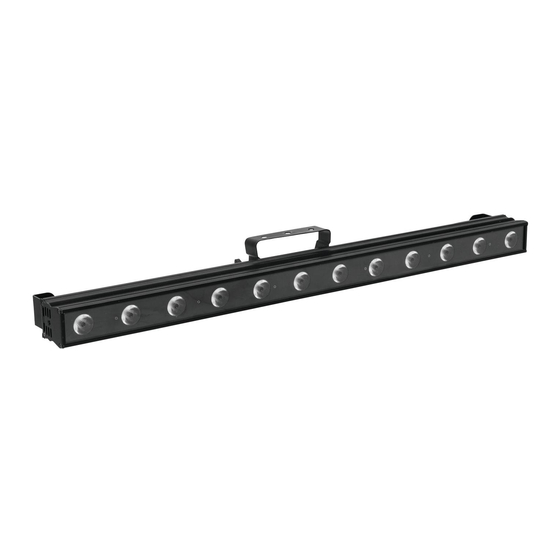
DESCRIPTION OF THE DEVICE Features LED color changing bar with 8 W QCLs • Equipped with 12 quadcolor LEDs in the colors red, green, blue and white • 4, 6, 10, 48 or 52 DMX channels selectable • Each LED can be controlled individually •... -
Page 24: Installation
INSTALLATION Rigging The device can be placed directly on the stage floor or rigged in any orientation on a truss without altering its operation characteristics. Fixed installation or mounting on a trussing system possible.. Overhead rigging DANGER TO LIFE! Please consider the EN 60598-2-17and the respective national standards during the installation! The installation must only be carried out by an authorized dealer! The installation of the device has to be built and constructed in a way that it can hold 10 times the weight for 1 hour without any harming deformation. -
Page 25: Fixed Installation
For overhead use, always install an appropriate safety bond. You must only use safety bonds and quick links complying with DIN 56927, shackles complying with DIN EN 1677-1 and BGV C1 carbines. The safety bonds, quick links, shackles and the carbines must be sufficiently dimensioned and used correctly in accordance with the latest industrial safety regulations (e. -
Page 26: Dmx-512 Connection
DMX-512 connection The wires must not come into contact with each other, otherwise the fixtures will not work at all, or will not work properly. Please note, the starting address depends upon which controller is being used. Only use a stereo shielded cable and 3-pin XLR-plugs and connectors in order to connect the controller with the fixture or one fixture with another. -
Page 27: Connection With The Mains
Connection with the mains Connect the device to the mains with the enclosed power supply cable. The occupation of the connection-cables is as follows: Cable International Brown Live Blue Neutral Yellow/Green Earth The earth has to be connected! If the device will be directly connected with the local power supply network, a disconnection switch with a minimum opening of 3 mm at every pole has to be included in the permanent electrical installation. -
Page 28: Dmx-Mode
DMX-Mode The device has five different DMX channel modes. The Control Board allows you, as described below, to assign the DMX channel mode. Addressing Press the MODE button until the display shows Address. You can now set the desired address via the UP or DOWN buttons. - Page 29 Red 100% / green increasing / blue 131 150 83 96 51% 59% increasing Red decreasing / green decreasing / blue 151 170 97 AA 59% 67% 100% Red 100% / green 100% / blue 100% / 171 200 AB C8 67% 78% white 100% 201 205 C9 CD 79% 80% WHITE color temperature 1...
- Page 30 White 1 255 00 FF 0% 100% White 0 - 100 % increasing Red 2 255 00 FF 0% 100% Red 0 - 100 % increasing Green 2 255 00 FF 0% 100% Green 0 - 100 % increasing Blue 2 255 00 FF 0% 100% Blue 0 - 100 % increasing...
- Page 31 255 00 FF 0% 100% Green 0 - 100 % increasing Blue 7 255 00 FF 0% 100% Blue 0 - 100 % increasing White 7 255 00 FF 0% 100% White 0 - 100 % increasing Red 8 255 00 FF 0% 100% Red 0 - 100 % increasing Green 8...
-
Page 32: Control Board
Control Board The Control Board offers several features: you can simply set the starting address, run the pre-programmed program or select a DMX channel mode. Browse through the menu by pressing Mode. Press Enter in order MODE to select the desired menu. You can change the selection by pressing Up or Down. -
Page 33: Cleaning And Maintenance
Dimmer speed (step response) M o d e Off : Response characteristics of LEDs < O f > M o d e DIM 1: Response characteristics of halogen lamps, fast < D I 1 > DIM 2: < D I 1 >... -
Page 34: Replacing The Fuse
Replacing the fuse If the fine-wire fuse of the device fuses, only replace the fuse by a fuse of same type and rating. Before replacing the fuse, unplug mains lead. Procedure: Step 1: Unscrew the fuseholder on the rearpanel with a fitting screwdriver from the housing (anti- clockwise).
Need help?
Do you have a question about the POS-12 POWERSTICK Color Changer and is the answer not in the manual?
Questions and answers