Table of Contents
Advertisement
Quick Links
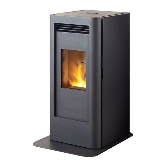
Greenfire GF40-2 Freestanding Pellet Stove
Model
Heat Output BTUs
Emissions (grams/hr) EPA Certified
Efficiency (EPA HHV)*/**
Efficiency (EPA LHV)**
Flue Size
US Biomass Tax Rebate Eligible**
*US Biomass Tax Rebate eligibility is based on the HHV value being
greater than or equal to 75%.
**When using optional top vent adaptor kit (GF40-920) and 3'' to 6''
flue adptor (3PVP-X6). See manual for further information.
UNIT DIMENSIONS
GF40-2
6,881 - 23,892 BTUs
0.54 grams/hr
80.2%
87.4%
3" (76mm)
Yes
Weight (with full hopper): 280 lb (127 Kg)
Hopper Capacity: up to 67 lb (28 Kg)
Voltage: 110 - 120 V
Max Current: 4.1 Amps
Consumption on High: 3.1 lb/hr (1.4 Kg/hr)*
Consumption on Low: 1.3 lb/hr (0.6 Kg/hr)*
(Note: Consumption will vary with the type of fuel used.)
GF40-2 Pellet Stove |
1
Advertisement
Table of Contents

Subscribe to Our Youtube Channel
Related Manuals for Regency Fireplace Products Greenfire GF40-2


Summary of Contents for Regency Fireplace Products Greenfire GF40-2
- Page 1 Greenfire GF40-2 Freestanding Pellet Stove Model GF40-2 Heat Output BTUs 6,881 - 23,892 BTUs Emissions (grams/hr) EPA Certified 0.54 grams/hr Efficiency (EPA HHV)*/** 80.2% Efficiency (EPA LHV)** 87.4% Flue Size 3" (76mm) US Biomass Tax Rebate Eligible** *US Biomass Tax Rebate eligibility is based on the HHV value being greater than or equal to 75%.
-
Page 2: Clearances To Combustibles
CLEARANCES TO COMBUSTIBLES IMPORTANT: The GF40-2 must have a Hearth Pad when installing the unit on a combustible floor. The included hearth pad meet all the requirement of a proper hearth pad. If you do not use the included hearth pad a certified non combustible Hearth Pad with a minimum R Value of at least 0.84 must be placed underneath the unit and extend six inches in front of the unit measured from the glass. -
Page 3: Vent Termination Requirements
VENT TERMINATION REQUIREMENTS IT IS HIGHLY RECOMMENDED THAT YOUR PELLET STOVE BE INSTALLED BY AN AUTHORIZED DEALER/INSTALLER. Table 1: Use in conjunction with Figure 6 for allowable exterior vent termination locations. Letter Minimum Clearance Description 24 in (61 cm) Above grass, top of plants, wood, or any other combustible materials. 48 in (122 cm) Beside/below any door or window that may be opened. -
Page 4: Mobile Home Installation
MOBILE HOME INSTALLATION • Secure the heater to the floor using the two holes in the base. • Ensure the unit is electrically grounded to the chassis of your home (permanently). • Do not install in a room people sleep in. •... -
Page 5: Horizontal Exhaust Through Wall Installation
HORIZONTAL EXHAUST THROUGH WALL INSTALLATION Vent installation: install vent at clearances specified by the vent manufacturer. A chimney connector shall not pass through an attic or roof space, closet or similar concealed spaces, or a floor, or ceiling. Where passage through a wall or partition of combustible construction is desired, the installation shall conform to CAN/CSA-B365 Installation Code for Solid-Fuel-Burning Appliances and Equipment. - Page 6 THROUGH WALL VERTICAL RISE HORIZONTAL TERMINATION INSTALLATION - FREESTAND- A termination cap is always recommended for this type of install but a stainless steel termination hood or a 45° elbow may be used in place of the cap. Figure 1 is the recommended installation set up, venting length is negligible. Figure 2 is the installation to use if there is a concrete or retaining wall in line with exhaust vent on a pellet stove.
-
Page 7: Inside Vertical Installation
INSIDE VERTICAL INSTALLATIONS To accomplish a outside vertical pipe installation, follow steps 1 through 5 in the “i ” section and then finish nsiDe erticaL nstaLLations reestanDing it by performing the following (refer to Figure at the bottom of this page). Choose a stove location that is ideal. -
Page 8: Hearth Mount Installation
Rain Cap Steel Plate or Flashing Flexible or Rigid 6" Stainless Steel Liner HEARTH MOUNT INSTALLATION Refer to Figures 16 and 17. Damper Removed 1. Install the hearth pad. or Fastened Open 2. Lock the fireplace damper in the open position. 10"...
Need help?
Do you have a question about the Greenfire GF40-2 and is the answer not in the manual?
Questions and answers