Table of Contents
Advertisement
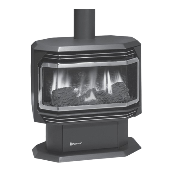
ULTIMATE™ U38 Freestanding Gas Stove
WARNING
FIRE OR EXPLOSION HAZARD
Failure to follow safety warnings exactly could result in serious
injury, death, or property damage.
- Do not store or use gasoline or other flammable vapors and liquids in the vicinity of this or any other
appliance.
- WHAT TO DO IF YOU SMELL GAS
• Do not try to light any appliance.
• Do not touch any electrical switch: do not use any phone in your building.
Leave the building immediately.
• Immediately call your gas supplier from a neighbour's phone. Follow the gas supplier's
instructions.
• If you cannot reach you gas supplier, call the fire department.
Installation and service must be performed by a qualified installer, service agency or the gas supplier.
Tested by:
919-480
FPI FIREPLACE PRODUCTS INTERNATIONAL LTD. 6988 Venture St., Delta, BC Canada, V4G 1H4
MODELS: U38-NG10 Natural Gas
Installer: Please complete the details on the back cover
and leave this manual with the homeowner.
Homeowner: Please keep these instructions for future reference.
U38-LP10 Propane
Owners &
Installation Manual
U38-39 Video
www.regency-fire.com
09.17.15
Advertisement
Table of Contents

Subscribe to Our Youtube Channel
Related Manuals for Regency Fireplace Products ULTIMATE U38


Summary of Contents for Regency Fireplace Products ULTIMATE U38
- Page 1 Owners & ULTIMATE™ U38 Freestanding Gas Stove Installation Manual U38-39 Video www.regency-fire.com MODELS: U38-NG10 Natural Gas U38-LP10 Propane WARNING FIRE OR EXPLOSION HAZARD Failure to follow safety warnings exactly could result in serious injury, death, or property damage. - Do not store or use gasoline or other flammable vapors and liquids in the vicinity of this or any other appliance.
- Page 2 To the New Owner: Congratulations! You are the owner of a state-of-the-art ULTIMATE Gas Stove by FIREPLACE PROD- UCTS INTERNATIONAL LTD. The Regency Gas Series of hand crafted appliances has been designed ® to provide you with all the warmth and charm of a woodstove, at the flick of a switch. The models U38- NG10, and U38-LP10 of this series has been approved by Warnock Hersey/Intertek for both safety and efficiency.
-
Page 3: Table Of Contents
table of contents Safety Label for the U38-10...........5 Aeration Adjustment ............22 Before You Start ............7 Normal Operating Sounds of Important Message ............8 Gas Appliances............22 General Safety Information..........8 Maintenance Instructions..........23 Clearances to Combustibles..........9 Log Replacement ............23 Optional Outside Air............9 Door and Glass Gasket ..........23 Draft Hood ..............10 Glass Replacement .............23 High Elevation .............10... - Page 4 dimensions 8 " 4.000 COLLAR 16 " 17" FIREPLACE PRODUCTS INTERNATIONAL 3RD ANGLE TOLERANCES UNLESS PROJECTION OTHERWISE STATED ±1° ANGULAR = PART : U38 MAIN ASSY ALVARO URRUTIA DEC 03 2014 ±0.031 DIMENSIONS = MAT'L : BLANK SIZE : SEE ABOVE INSIDE BEND RADII = DO NOT PROCESS :...
-
Page 5: Safety Label For The U38-10
safety decal This is a copy of the label that accompanies NOTE: Regency units are constantly being ® each ULTIMATE Freestanding Gas Stove. We improved. Check the label on the unit and if have printed a copy of the contents here for your there is a difference, the label on the unit is the review. - Page 6 requirements MA Code - CO Detector (for the State of Massachusetts only) 5.08: Modifications to NFPA-54, Chapter 10 (2) Revise 10.8.3 by adding the following additional requirements: (a) For all side wall horizontally vented gas fueled equipment installed in every dwelling, building or structure used in whole or in part for residential purposes, including those owned or operated by the Commonwealth and where the side wall exhaust vent termination is less than seven (7) feet above finished grade in the area of the venting, including but not limited to decks and porches, the following requirements shall be satisfied:...
-
Page 7: Before You Start
installation YOUNG CHILDREN SHOULD BE CARE- FULLY SUPERVISED WHEN THEY ARE BEFORE YOU START IN THE SAME AREA AS THE APPLI- ANCE. TODDLERS, YOUNG CHILDREN Safe installation and operation of this appliance AND OTHERS MAY BE SUSCEPTIBLE requires common sense, however, we are required TO ACCIDENTAL CONTACT BURNS. -
Page 8: Important Message
installation IMPORTANT MESSAGE 12) Under no circumstances should this appliance 5) Make gas connections. Refer to "Gas be modified. Parts that have to be removed for Connection" section. SAVE THESE servicing should be replaced prior to operating this appliance. Test the pilot. Must be as per diagram. Refer INSTRUCTIONS to "Pilot Adjustment"... -
Page 9: Clearances To Combustibles
installation CLEARANCES TO OPTIONAL COMBUSTIBLES OUTSIDE AIR The clearances listed below are MINIMUM dis- Outside air for combustion can be brought in tances. Measure the clearance to both the appli- either through the bottom of the pedestal or ance and the chimney connector. (The farthest Minimum ceiling through the rear plate of the pedestal. -
Page 10: Draft Hood
installation VENTING Vent Terminations DRAFT HOOD This heater is a vented appliance and must be This heater has a draft hood built in. It must not connected to a chimney/flue in accordance with be altered, obstructed, or blocked in any way, and the installation codes. -
Page 11: Gas Connection
installation GAS CONNECTION 4) Light the pilot and turn the valve to "ON" position. System Data U38-10 Converted to 30,000 Btu 5) The pressure check should be carried out with The gas line can be rigid pipe, or to make instal- For 0 to 4500 feet altitude lation easier, use a listed flexible connector if the unit burning and the setting should be within... -
Page 12: Conversion Kit# 732-969 From Ng To Lp
installation Conversion from NG to LPG using SIT 829 NOVA Gas Valve CONVERSION KIT# 732-969 FROM NG TO LP THIS CONVERSION MUST BE DONE BY A QUALIFIED GAS FITTER THIS CONVERSION MUST BE DONE BY A QUALIFIED GAS FITTER THIS CONVERSION MUST BE DONE BY A QUALIFIED GAS FITTER IF IN DOUBT DO NOT DO THIS CONVERSION !! IF IN DOUBT DO NOT DO THIS CONVERSION !! IF IN DOUBT DO NOT DO THIS CONVERSION !! 6. -
Page 13: Conversion To Lower Btu Rating
installation CONVERSION TO LOWER BTU RATING THIS CONVERSION MUST BE DONE BY A QUALIFIED GAS FITTER IF IN DOUBT DO NOT DO THIS CONVERSION !! Natural Gas Conversion Kit 730-920 Contains: 6) Remove burner orifice with a 1/2" wrench Qty. Part # Description and discard. -
Page 14: Log Set Installation
GAS STOVES installation U37 / U38 / U39 LOG SET INSTALLATION LOG SET INSTALLATION 2) Sprinkle the embers on the left and right sides of the Read the instructions below carefully and refer to fi rebox base. the diagrams. If logs are broken do not use the unit until they are replaced. - Page 15 GAS STOVES installation U37 / U38 / U39 5) Sprinkle some lava rock just in front of B) 8) Place Front Right Log E)02-45 on the two pins as 02-56 on the burner holes. shown. B)02-56 E)02-45 Lava Rock 6) Place Front Left Log C)02-44 onto the 2 front pins as shown.
- Page 16 GAS STOVES installation U37 / U38 / U39 11) Place the notch in Center Log F)02-47 over Log E)02-45 and across the cutout on Log A)02- G)02-48 E)02-45 F)02-47 A)02-65 Side E)02-45 View Bracket Notch Cutout The bottom right edge of Log G)02-48 must sit snugly against the bracket 12) Position notch in Front Right Log G)02-48 on Log F)02-47 and push the bottom right edge against the...
-
Page 17: Front Door Installation
installation FRONT DOOR LOUVER The smoke should be drawn into the draft hood. If the smoke is not drawn into the draft INSTALLATION INSTALLATION hood, turn the unit off and check for the cause of lack of draft. (packaged separately) 1) Attach the top &... -
Page 18: Wall Thermostat
installation 5. Open the battery compartment door on the DC SPARK IGNITER DC spark box OPTIONAL BATTERY INSTALL 6. Install battery into DC spark box. WALL THERMOSTAT Install supplied battery into the DC spark box. A wall thermostat may be installed if desired. Connect the wires as per the wiring diagrams. -
Page 19: Wiring Diagrams
installation WIRING DIAGRAMS This heater does not require a 120V A.C. sup- NOTE: Even if the fan is not purchased (Do not cut the ground terminal off under ply for operation. In case of a power failure, the with the unit, it is still a good idea to any circumstances.) burner switch and the optional remote control/ bring power to the receptacle box... -
Page 20: First Fire
operating instructions FIRST FIRE 8) Hook up remote receiver to wire marked 'receiver' which will be located on the bottom of the appli- 5. Press and release the ON/OFF button on the ance. This remote control requires coding. See remote handheld transmitter. An audible beep The first fire in your stove is part of the paint curing remote control instructions for details. -
Page 21: Copy Of The Lighting Plate Instructions
operating instructions COPY OF THE LIGHTING PLATE INSTRUCTIONS FOR YOUR SAFETY READ BEFORE LIGHTING This appliance must be installed in accordance with local codes, if any; if none, follow the National Fuel Gas Code, ANSI Z223.1/NFPA 54, or Natural Gas and Propane Installation Codes, CSA B149.1. WARNING: If you do not follow these instructions exactly, a fire or explosion may result causing property damage, personal injury or loss of life. -
Page 22: Pilot Adjustment
operating instructions PILOT ADJUSTMENT AERATION NORMAL OPERATING ADJUSTMENT SOUNDS OF Periodically check the pilot flames. Correct GAS APPLIANCES flame pattern has three strong blue flames: 1 The burner aeration is factory set but may need flowing around the thermopile and 1 around the adjusting due to either the local gas supply or thermocouple, and 1 flowing across the rear of altitude. -
Page 23: Maintenance Instructions
maintenance MAINTENANCE CLOTHING OR OTHER FLAM- MABLE MATERIAL SHOULD NOT INSTRUCTIONS BE PLACED ON OR NEAR THE APPLIANCE. 1) Always shut the valve off before cleaning. For relighting, refer to lighting instructions. Keep DO NOT USE THIS APPLIANCE IF the burner and control compartment clean by brushing and vacuuming at least once a year. -
Page 24: Fan Maintenance
maintenance PANEL DOOR IMPORTANT Disconnect power supply 1) Remove the door from the unit and place 5) Lift fan off of the 2 pins, tip back and pull before servicing on a soft surface to prevent scratching. through firebox opening. Disconnect the green ground wire from the left side of the 2) Pull out the door gasket. -
Page 25: Valve Replacement
maintenance VALVE REPLACEMENT If your valve requires maintenance or replace- ment, follow these instructions: NOTE: Always shut off the gas and electrical supply before removing the valve. 1) Remove safety screen and open front pedestal door. You may want to put a soft cloth on the base of the unit so that when the pedestal door is open it doesn't scratch the paint. -
Page 26: U38-10 Main Assembly
parts list U38-10 MAIN ASSEMBLY Part # Description Part # Description 732-929 Safety Screen 948-255 Door Latch c/w Hook 560-920 Top/Bottom Gold Louver Assy 910-250 Spill Switch 560-921 Top/Bottom Brush Nickel Assy 910-233 Thermodisc - Fan Auto/On/Off 560-922 Top/Bottom Black Louver Assy Mounting Bracket - Fan Thermodisc 560-055 Fan Access Door... -
Page 27: U38-10 Burner & Log Assembly
parts list U38-10 BURNER & LOG ASSEMBLY Part # Description 732-574/P Valve Assembly- Natural Gas 732-576/P Valve Assembly - Propane 910-578 Valve Only- Natural Gas 910-580 Valve Only - Propane 910-038 Pilot Assy - S.I.T. - 3 Flame NG 910-039 Pilot Assy - S.I.T. -
Page 28: U38-10 Door Assembly
parts list U38-10 DOOR ASSEMBLY Part # Description 730-932 Gold Wrap Door - Complete 730-933 Black Wrap Door - Complete 730-934 Brushed Nickel Wrap Door - Complete 101) 846-570 Door Gasket Kit 105) Ceramic Paper 107) 936-243 Glass Gasket 111) Door Frame Fibre Paper 208) 940-325/P... - Page 29 notes Regency U38-10 ULTIMATE Freestanding Gas Stove ®...
- Page 30 notes 30 | Regency U38-10 ULTIMATE Freestanding Gas Stove ®...
-
Page 31: Warranty
warranty Gas Product Warranty 2015 Regency® Fireplace Products are designed with reliability and simplicity in mind. In addition, our internal Quality Assurance Team carefully inspects each unit thorough- ly before it leaves our facility. Regency® Fireplace Products is pleased to extend this limited lifetime warranty to the original purchaser of a Regency® Product. This warranty is not transferable. - Page 32 Register your Regency warranty online ® www.regency-fire.com Reasons to register your product online today! • View and modify a list of all your registered products. • Request automatic email notification of new product updates. • Stay informed about the current promotions, events, and special offers on related products.
Need help?
Do you have a question about the ULTIMATE U38 and is the answer not in the manual?
Questions and answers