Table of Contents
Advertisement
Owners &
Installation
LISTINGS AND CODE APPROVALS
These gas appliances have been
tested in accordance with AG 103,
NZS 5262 and have been certified
by the Australian Gas Association
for installation and operation as
described in these Installation and
Operating Instructions.
Your unit should be serviced an-
nually by an authorised service
person.
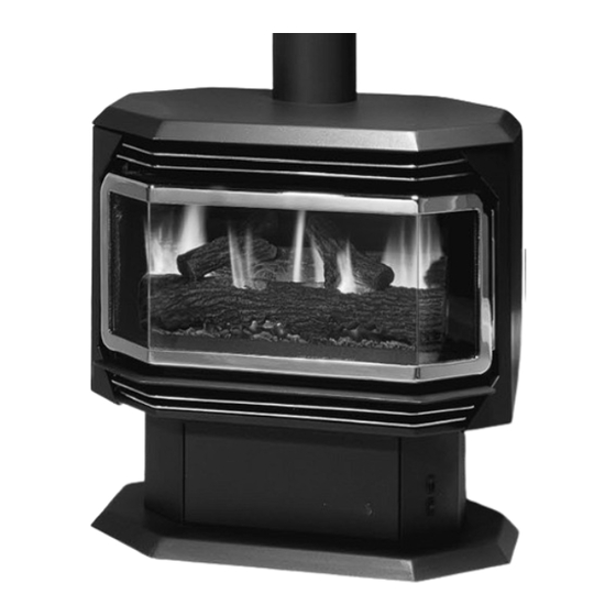
Freestanding Gas Stove
PLEASE KEEP THESE INSTRUCTIONS
FOR FUTURE REFERENCE
WARNING:
Improper installation, adjustment, altera-
tion, service or maintenance can cause
injury or property damage. Refer to this
manual. For assistance or additional in-
formation consult an authorized installer,
service agency or the gas supplier.
FOR YOUR SAFETY
Do not store or use gasoline or other flam-
mable vapours and liquids in the vicinity of
this or any other appliance.
Installation and service must be performed
by an authorized installer, service agency or
the gas supplier.
908-060
Models: F43-NG
F43-LP
F28-NG
F28-LP
FOR YOUR SAFETY
What to do if you smell gas:
Do not try to light any appli-
ance
Do not touch any electri-
cal switch: do not use any
phone in your building.
Immediately call your gas
supplier from a neighbour's
phone. Follow the gas sup-
plier's instructions.
If you cannot reach your
gas supplier, call the fire
department.
Natural Gas
Propane
Natural Gas
Propane
07/24/02
Advertisement
Table of Contents

Subscribe to Our Youtube Channel
Related Manuals for Regency Fireplace Products F43-NG


Summary of Contents for Regency Fireplace Products F43-NG
- Page 1 Owners & Installation Freestanding Gas Stove Models: F43-NG Natural Gas F43-LP Propane F28-NG Natural Gas F28-LP Propane PLEASE KEEP THESE INSTRUCTIONS FOR FUTURE REFERENCE WARNING: FOR YOUR SAFETY Improper installation, adjustment, altera- What to do if you smell gas: tion, service or maintenance can cause ...
- Page 2 The models F43-NG, F43-LP, F28-NG, and F28-LP of this series has been approved by Australian Gas As- sociation for both safety and efficiency. As it also bears our own mark, it promises to provide you with economy, comfort and security for many trouble free years to follow.
-
Page 3: Table Of Contents
TAbLE OF CONTENTS Page Page Safety Label Copy of Lighting Plate Instructions ....Data Plate ............ 4 Shutdown Instructions ....... 13 First Fire ............ 13 Installation Convection Fan Operation......13 Flame Height Adjustment ......13 General Installation Information....5 Pilot Adjustment ......... 13 Installation Checklist ........ -
Page 4: Data Plate
SAFETY LAbEL This is a copy of the label that accompanies DATA BADGE NOTE: Regency units are con- each Regency F43 Freestanding Gas Heater. stantly being improved. Check the label on the We have printed a copy of the contents here unit and if there is a difference, the label on the for your review. -
Page 5: General Installation Information
INSTALLATION IMPORTANT: We recommend that you plan your installa- tion on paper using exact measurements for GENERAL SAFETY IN- clearances and floor protection before actually The F43 Freestanding Gas Stove must be FORMATION installing this appliance. If an existing chimney is installed in accordance with these instructions. -
Page 6: Minimum Clearances To Combustibles
9) Final check, page 11. 100mm flue. Before leaving this unit with the customer, the F43-NG & F43-LP Clearances installer must ensure that the appliance is fir- ing correctly and operation fully explained to customer. -
Page 7: Flueing
INSTALLATION Note: The rear pedestal cover plate must System Data - F43-NG & F43-LP always be fitted for safety. Electrical System Data - F28-NG & F28-LP connections inside. For 0 to 610 meters altitude For 0 to 1372 meters altitude... -
Page 8: Log Installation - F43
INSTALLATION diagrams. If logs are broken do not use the WARNING: Dangerous operating conditions unit until they are replaced. broken logs can may occur if these logs are not positioned interfere with the pilot and burner operation. in their approved locations. Read the in- structions below carefully and refer to the The gas log kit contains the following: a) Front Right Log - Part # 902-192... -
Page 9: Door Installation And Door Latch
INSTALLATION FRONT DOOR setting. If they are too hard or too easy to close, you may want to adjust them by INSTALLATION loosening the latch catch. See diagram 3. 5) Remove the blue plastic protective coating 1) Open the two side panels. from the glass. -
Page 10: Wiring Diagram - F43
INSTALLATION WIRING DIAGRAM - F43 WIRING DIAGRAM - F28 Regency F28/F43 Freestanding Gas Heater... -
Page 11: Optional Wall Thermostat
OPERATING INSTRUCTIONS OPTIONAL OPTIONAL REMOTE OPERATING WALL THERMOSTAT CONTROL INSTRUCTIONS INSTALLATION INSTALLATION Before operating this appliance, proceed through the following check list. A wall thermostat may be installed if desired. Use the Regency Remote Control Kit (Part # use chart below to determine thermostat wire 1) Read and understand these instructions 910-358/P) approved for this unit. -
Page 12: Copy Of Lighting Plate Instructions
OPERATING INSTRUCTIONS COPY OF THE LIGHTING PLATE INSTRUCTIONS Regency F28/F43 Freestanding Gas Heater... -
Page 13: Shutdown Instructions
OPERATING INSTRUCTIONS AUTOMATIC 5) Push in PILOT knob all the way in and ADJUSTING FLAME hold. Immediately push IGNITOR button CONVECTION FAN OP- until pilot lights. Continue to hold the PILOT HEIGHT knob in for approximately one minute, then ERATION release the PILOT knob. -
Page 14: Aeration Adjustment
Replace logs and embers from your gas appliance. This is perfectly normal as per instructions on page 8. due to the fact that there are various gauges F43-NG Natural Gas: 1/4" open and types of steel used within your appliance. F43-LP... -
Page 15: Maintenance
MAINTENANCE where previously glued and put in place. Note: Wearing gloves will protect your MAINTENANCE 4) Install side retainers. hands while handling glass. INSTRUCTIONS 5) Install door catch plate. 1) Remove the door from the unit and place on a soft surface to prevent scratching. SERVICE ANNUALLY ONLY bY 6) Install the 24 nuts loosly, do not tighten yet. -
Page 16: Fan Maintenance - F28
MAINTENANCE 1) unplug or disconnect power source to stove. To remove F28 fan: Reverse steps (1-5 on removing the fan). If necessary install a new gasket (Part# 936-196) 2) Remove all logs and the rear log support, before replacing the fan access panel. Make 1) unplug or disconnect power source to stove. -
Page 17: Removing Valve
MAINTENANCE REMOVING VALVE 8) Remove eight 1/4" hex head screws holding removing two screws per side. See diagram the burner tray assembly in place. below. 9) Carefully lift the burner tray assembly out. If your valve requires maintenance or replace- ment, follow these instructions: NOTE: Always shut off the gas supply... -
Page 18: Troubleshooting Guide
MAINTENANCE TROUbLESHOOTING THE GAS CONTROL SYSTEM Note: before troubleshooting the gas control system, be sure external gas shut off is in the "on" position. • WARNING • bEFORE DOING ANY GAS CONTROL SERVICE WORK, REMOVE THE GLASS FRONT. TROUbLESHOOTING GUIDE POSSIbLE PRObLEM CAUSES... -
Page 19: Parts List - F43
PARTS LIST F43 MAIN ASSEMbLY Part # Description Part # Description 29) * Thermodisc Cover 590-513 Louvre Assembly Bottom 30) 591-175 Rear Panel 590-514 Louvre Assembly Top 651-135 Door Safety Screen (Aust. only) 32) 591-187 Firebox Baffle Wire Holder Clip 33) 591-576 False Top Assembly Snap Bushing... - Page 20 PARTS LIST F43 bURNER & LOG ASSEMbLIES Part # Description Part # Description 910-246 ON/OFF Burner Switch (2-way) 910-022 Pilot Assy-SIT- 3 flame - N.G. 910-190 Piezo Ignitor & Nut 910-025 Pilot Assy-SIT- 4 flame - Propane 910-140 HI/OFF/LO Fan Switch 910-386 Thermocouple 910-373...
- Page 21 PARTS LIST F43 DOOR ASSEMbLIES Part # Description 650-975 Gold Door - Complete Assy 650-974 Black Door - Complete Assy 101) 650-920 Door Gasket Kit 103) 590-190 Glass Retainer Side 104) 650-190 Glass Retainer Side-Top/Bottom 105) 650-189 Glass Retainer Front 106) 940-226/P Side Glass...
-
Page 22: Parts List - F28
PARTS LIST F28 MAIN ASSEMbLY Part # Description Part # Description 560-070 Door Screen (Aust. only) 904-258 Side Panel Door Magnet 560-555/02 Top/Bottom Gold Louvre Assy 948-255 Door Latch Wire Holder Clip 910-250 Spill Switch Snap Bushing 910-233 Thermodisc - Fan Auto/On/Off Grommet for power cord Mounting Bracket - Fan Thermodisc 560-055... - Page 23 PARTS LIST F28 bURNER & LOG ASSEMbLY Part # Description Part # Description 910-022 Pilot Assy-SIT- 3 flame - N.G. 910-246 ON/OFF Burner Switch (2-way) 910-023 Pilot Assy-SIT- 3 flame- Propane 910-190 Piezo Ignitor & Nut 910-386 Thermocouple 910-140 HI/OFF/LO Fan Switch 910-373 Knob - Pilot Valve Extension 910-341...
- Page 24 PARTS LIST F28 DOOR ASSEMbLIES Part # Description 560-924 Gold Door - Complete Assy 560-926 Black Door - Complete Assy 101) 650-920 Door Gasket Repair Kit 106) 940-236/P Side Glass 107) 936-243 Glass Gasket 108) 940-237/P Centre Glass 112) 560-032 Door Glass Aluminium Extrusion 114) * Ceramic Paper 1/16"...
- Page 25 NOTES ___________________________________________________ __________________________________ ___________________________________________________ _________ ___________________________________________________ _______ ___________________________________________________ _________ ___________________________________________________ ____ ___________________________________________________ ___________________________________________________ _______ ___________________________________________________ ______ ___________________________________________________ ______ ___________________________________________________ ___________________________________________________ ___________________________________________________ ____________ Regency F28/F43 Freestanding Gas Heater...
- Page 26 NOTES ___________________________________________________ __________________________________ ___________________________________________________ _________ ___________________________________________________ _______ ___________________________________________________ _________ ___________________________________________________ ____ ___________________________________________________ ___________________________________________________ _______ ___________________________________________________ ______ ___________________________________________________ ______ ___________________________________________________ ___________________________________________________ ___________________________________________________ ____________ Regency F28/F43 Freestanding Gas Heater...
-
Page 27: Warranty
WARRANTY Exclusions: Regency Fireplace Products are designed with reli- This limited Lifetime Warranty does not extend to or ability and simplicity in mind. In addition, our internal include paint, door or glass gasketing or trim. It does Quality Assurance Team carefully inspects each unit not cover installation and operational related problems thoroughly before it leaves our door. - Page 28 Printed in Canada...
-
Page 29: Operating Instructions
operating instructions operating instructions Push in PILOT knob all the way in and hold. Immediately push IGNITOR button until pilot lights. Continue to hold the PILOT knob in for approximately one minute, then Before operating this appliance, proceed through the release the PILOT knob. The pilot flame should continue following check list. to burn. If the pilot does not remain lit, repeat operation allowing a longer period before releasing PILOT knob. Read and understand these instructions before operating this appliance. - Page 30 operating instructions copy of the Lighting plate instructions Masport Freestanding Gas Heater...
-
Page 31: Adjusting Flame Height
operating instructions operation piLot aDJustMent The fan operates automatically - turn the knob in the pedestal Periodically check the pilot flames. Correct flame pattern has base to High or Low speed. The fan will turn on as the stove four strong blue flames: 1 flowing around the thermopile and comes up to operating temperature. After the unit has been 1 around the thermocouple, 1 flowing across the rear burner turned off and cools to below a useful heat output range the and 1 reaching towards the front burner (it does not have to... - Page 32 IIt is possible that you will hear some sounds from your gas appliance. This is perfectly normal due to the fact that there F43-NG Natural Gas: 1/4" open are various gauges and types of steel used within your ap- F43-LP Propane: Fully open (rear) and pliance.
- Page 33 Maintenance DO NOT USE THIS APPLIANCE IF ANY PART HAS BEEN UNDER WATER. IMMEDIATELY CALL A AUTHORIZED SERVICE TECHNI- 2) Clean glass (never when unit is hot), appliance, louvres, CIAN TO INSPECT THE APPLIANCE AND TO REPLACE ANY PART and door with a damp cloth. Never use an abrasive OF CONTROL SYSTEM AND ANY GAS CONTROL WHICH HAS cleaner.
- Page 34 Maintenance gLass repLaceMent 11) Install door onto stove and check the seal. Your Masport heater is supplied with high temperature, 5mm Neoceram silica coated ceramic glass that will withstand the highest heat that your unit will produce. In the event that you break your glass, purchase your replacement from an authorized Masport dealer only, and follow the step-by-step instructions for replacement. removing glass: Note: Wearing gloves will protect your hands while han- dling glass.
- Page 35 Maintenance iMportant:these fans collect a lot of dust from within your home. ensure you maintain these fan motors on a regular basis by vacuuming out the fan squirrel cages, around the motor, and around the grills on the back of the stove. Warning: electrical grounding instructions this appliance is equipped with a three pronged (grounding) plug for your protection against shock hazard and should...
- Page 36 Maintenance 2) Remove all logs and the rear log support, then remove the 10 screws holding the access panel in place, see Diagram 1. (Fan can also be accessed from the right side by open- ing the right side door. See Diagram 2). 3) Unclip the black, red and white wires from the fan motor. 4) Lift fan off of the 2 pins, tip back and pull through firebox opening. Disconnect the green ground wire from the left side of the fan as soon as you can reach it. replacing F28 Fan: Reverse the above steps (1 - 4).
- Page 37 Maintenance reMoVing VaLVe Disconnect all wires from the back of the panel and then remove panel. You should lay the panel on a soft cloth If your valve requires maintenance or replacement, follow so it doesn't get marked up. See diagram below. these instructions: Remove the two outside frame pieces by removing two note: always shut off the gas supply before...
- Page 38 Maintenance tray assembly in place. At this point you should disconnect the gas at the valve. Carefully lift the burner tray assembly out. Remove the burner by removing the four 1/4" hex head screws. See diagram below. Note: Use a magnetic type screwdriver. Remove eight 1/4"...
-
Page 39: Troubleshooting The Gas Control System
Maintenance trouBLesHooting tHe gas controL sYsteM Note: Before troubleshooting the gas control system, be sure external gas shut off is in the "on" position. • WARNING • BeFore Doing anY gas controL serVice WorK, reMoVe tHe gLass Front. trouBLesHooting guiDe possiBLe proBLeM causes... - Page 40 parts List F43 Main asseMBLY part#: aust. new Zealand Description aust. new Zealand Description 590-513 560058 Louvre Assembly Bottom 590-514 556160 Louvre Assembly Top 29) 591-189 556061 Thermodisc Cover 651-135 Door Safety Screen (Aust. only) 30) 591-175 Rear Panel 32) 591-187 Firebox Baffle 910-199 551886 Wire Holder Clip...
- Page 41 parts List F43 Burner & Log asseMBLies part#: aust. new Zealand Description aust. new Zealand Description 51) 910-246 560024 ON/OFF Burner Switch(2-way) 75) 650-933 560047 Pkg. Log Set 52) 910-190 597004 Piezo Ignitor & Nut 53) 910-140 560036 HI/OFF/LO Fan Switch 78) 651-578 556066 Burner Assy-NG 54) 910-373...
- Page 42 parts List F43 Door asseMBLies part#: aust. new Zealand Description 650-975 Gold Door - Complete Assy 650-974 Black Door - Complete Assy 101) 650-920 560018 Door Gasket Kit 103) 590-190 590-190 Glass Retainer Side 104) 650-190 650-190 Glass Retainer Side-Top/Bottom 105) 650-189 650-189...
- Page 43 parts List F28 Main asseMBLY part#: aust. new Zealand Description aust. new Zealand Description 560-070 Door Screen (Aust. only) 21) 560-031 560242 Side Panel Door Hinge 560-555/02 560239 Top/Bottom Gold Louvre Assy 23) 904-258 551891 Side Panel Door Magnet 551886 Wire Holder Clip 24) 948-255 556074 Door Latch Snap Bushing...
- Page 44 parts List F28 Burner & Log asseMBLY part#: aust. new Zealand Description aust. new Zealand Description 75) 560-935 Log Set 51) 910-246 560024 ON/OFF Burner Switch (2-way) 52) 910-190 597004 Piezo Ignitor & Nut 78) 651-580 556176 Burner Assy 53) 910-140 560036 HI/OFF/LO Fan Switch 54) 910-373 588412 Knob - Pilot Valve Extension 55) 910-372...
- Page 45 parts List F28 Door asseMBLies part#: aust. new Zealand Description 560-924 Gold Door - Complete Assy 560-926 556094 Black Door - Complete Assy 101) 650-920 560018 Door Gasket Repair Kit 106) 940-236/P 560257 Side Glass 107) 936-243 560087 Glass Gasket 108) 940-237/P 560258 Centre Glass 112) 560-032...
- Page 46 notes _________________________________________________ ____________________________________ _________________________________________________ ___________ _________________________________________________ _________ _________________________________________________ ___________ _________________________________________________ ______ _________________________________________________ ____ _________________________________________________ _________ _________________________________________________ ________ _________________________________________________ ________ _________________________________________________ _____ _________________________________________________ _____ _________________________________________________ ______________ Masport Freestanding Gas Heater...
- Page 47 notes _________________________________________________ ____________________________________ _________________________________________________ ___________ _________________________________________________ _________ _________________________________________________ ___________ _________________________________________________ ______ _________________________________________________ ____ _________________________________________________ _________ _________________________________________________ ________ _________________________________________________ ________ _________________________________________________ _____ _________________________________________________ _____ _________________________________________________ ______________ Masport Freestanding Gas Heater...
- Page 48 notes _________________________________________________ ____________________________________ _________________________________________________ ___________ _________________________________________________ _________ _________________________________________________ ___________ _________________________________________________ ______ _________________________________________________ ____ _________________________________________________ _________ _________________________________________________ ________ _________________________________________________ ________ _________________________________________________ _____ _________________________________________________ _____ _________________________________________________ ______________ Masport Freestanding Gas Heater...
- Page 49 WarrantY tHe Masport express WarrantY All new Masport Gas appliances are warranted, subject to 1. Defects, malfunctions or failures caused by incorrect instal- the following conditions, to be free from defects in material or lation, normal wear and tear, misuse, neglect, accidental workmanship under normal use. The Express Warranty on all damage or failure to follow the fuel selection, product parts, including firebox components but excluding fans, flues operating and maintenance instructions, or resulting from and flue accessories is two years from date of original purchase installations, repairs or modifications to the equipment as well as labour costs involved in the repair or replacement.
- Page 50 Printed in Canada...
Need help?
Do you have a question about the F43-NG and is the answer not in the manual?
Questions and answers