Table of Contents
Advertisement
Quick Links
Owners &
Installation
LISTINGS AND CODE APPROVALS
These gas appliances have been tested in
accordance with AS4553, NZS 5262 and
have been certified by the Australian Gas
Association for installation and operation
as described in these Installation and
Operating Instructions.
Your unit should be serviced annually
by an authorised service person.
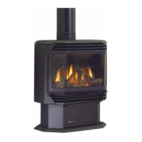
Freestanding Gas Stove
PLEASE KEEP THESE INSTRUCTIONS
FOR FUTURE REFERENCE
WARNING:
Improper installation, adjustment, altera-
tion, service or maintenance can cause
injury or property damage. Refer to this
manual. For assistance or additional in-
formation consult an authorized installer,
service agency or the gas supplier.
FOR YOUR SAFETY
Do not store or use gasoline or other flam-
mable vapours and liquids in the vicinity of
this or any other appliance.
Installation and service must be performed
by an authorized installer, service agency or
the gas supplier.
918-646g
Models: FG39NG1-BRA
FG39LPG1-BRA
FOR YOUR SAFETY
What to do if you smell gas:
Do not try to light any appli-
ance
Do not touch any electri-
cal switch: do not use any
phone in your building.
Immediately call your gas
supplier from a neighbour's
phone. Follow the gas sup-
plier's instructions.
If you cannot reach your
gas supplier, call the fire
department.
October 2, 2020
Advertisement
Table of Contents

Subscribe to Our Youtube Channel
Related Manuals for Regency Fireplace Products FG39NG1-BRA


Summary of Contents for Regency Fireplace Products FG39NG1-BRA
- Page 1 Owners & Installation Freestanding Gas Stove Models: FG39NG1-BRA FG39LPG1-BRA PLEASE KEEP THESE INSTRUCTIONS FOR FUTURE REFERENCE WARNING: FOR YOUR SAFETY Improper installation, adjustment, altera- What to do if you smell gas: tion, service or maintenance can cause Do not try to light any appli- injury or property damage.
- Page 2 Products International Ltd. The Regency Gas Series of hand crafted appliances has been designed to provide you with all the warmth and charm of a woodstove. The models FG39NG1-BRA and FG39LPG1- BRA of this series has been approved by AGA. As it also bears our own mark, it promises to provide you with economy, comfort and security for many trouble free years to follow.
- Page 3 UNIT SPECIFICATIONS Regency FG39-1 FireGenie Freestanding Gas Stove...
-
Page 4: Table Of Contents
TABLE OF CONTENTS Safety Label Operating Instructions Operating Instructions ..........24 Safety Label............. 5 Lighting Instructions..........24 Resetting the Unit ...........24 Installation Shutdown Instructions ..........24 First Fire ..............24 Specifications ............3 Fan Operation............24 Before You Start ............6 Adjusting Flame Height ..........24 General Safety Information........6 Summary of Controls ..........25 Installation Checklist ..........7 Pilot Adjustment ............25... -
Page 5: Safety Label
Regency Gas Fireplace Distributed by: Model Western Australia: Gas Type Air Group Australia 28 Division St Model FG39NG1-BRA FG39LPG1- BRA Welshpool, WA 6106 Gas Consumption Eastern Australia Fireplace Products Manifold Pressure 2.55 Australia Pty. Ltd. -
Page 6: Installation
OF HIGH SURFACE TEMPERA- SPECIFICATIONS TURES, ESPECIALLY THE FIRE- INFORMATION PLACE GLASS, AND SHOULD Fuels: FG39NG1-BRA is approved for use with STAY AWAY TO AVOID BURNS 1) The appliance shall be installed in accord- OR CLOTHING IGNITION. ance with the manufacturer's installation... -
Page 7: Installation Checklist
INSTALLATION 2) If required, adjusting the primary air to ensure 10) Be aware of electrical wiring locations in FG39NG1-BRA & FG39LPG1-BRA that the flame does not carbon. First allow walls and ceilings when cutting holes for Reference Dimensions the unit to burn for 15-20 min. to stabilize. -
Page 8: Louver Installation
Dura-Flue Room Sealed System Model side stove panel using 2 screws per the FG39NG1-BRA, and FG39LPG1-BRA. The DV-GS fluing systems, in combination with side. warranty will be voided and serious fire, health... -
Page 9: Exterior Flue Termination Locations
INSTALLATION EXTERIOR FLUE TERMINATION LOCATIONS Minimum clearances required for balanced flue terminals or the flue terminals of outdoor appliances according to AS5601-2004 (AGA gas installation code) or NZS 5261 (New Zealand) Minimum Clearance (mm) Below eaves, balconies or other projections: - Appliances up to 50 MJ/h input - Appliances over 50 MJ/h input From the ground or above a balcony... -
Page 10: Flueing Arrangements - Horizontal
INSTALLATION FLUEING ARRANGEMENTS Vertical Terminations Using Horizontal Terminations for All Fluing Systems Dura-Flue Fluing System for The shaded areas in the diagram below show all allowable combina- Residential Manufactured and Mobile Homes tions of vertical runs with horizontal terminations. Maximum one elbow (two 45 elbows equal one 90 elbow). -
Page 11: Dv Stove Horizontal Flue Kit
INSTALLATION DV STOVE HORIZONTAL FLUE KIT Horizontal Stove Flue Kit (Part # 946-112) includes all the parts needed to install the FG39 Free- standing Gas unit with minimum horizontal and vertical vent dimensions. For installations that require longer vertical and/or horizontal vents use the Dura-Vent system as shown in your manual. Qty. - Page 12 INSTALLATION d) Cut the 2 ft. (.6m) section of rigid pipe to length. Ensure that the pipe length when cut will seat onto both the starter elbow. Crimped collar and the 90 section of rigid pipe seats into the elbow. Only cut the uncrimped side of pipe.
-
Page 13: Dura-Flue Termination Kit
INSTALLATION DURA-FLUE above the roof line. Decorative brass trim kits Note: These are the minimum pieces re- are available for both wall thimbles and ceiling quired. Other parts may be required TERMINATION KIT support boxes. for your particular installation. See below for a list of flue parts. -
Page 14: Dura-Flue Horizontal Installation
INSTALLATION 990G Elbow-Swivel Galv. (diagram 1). Push the pipe sections b) The location of the horizontal flue termi- 945BG Elbow-Swivel-Black completely together, then twist-lock nation on an exterior wall must meet all Elbow Galv. one section clockwise approximately local and national building codes, and 990B Elbow-Black one-quarter turn, until the two sections... -
Page 15: Dura-Flue Vertical Termination Installation
INSTALLATION 6) Continue to assemble pipe lengths. Note: If an offset is necessary in the attic to avoid obstructions, it is important to support the flue pipe every 3 feet, to avoid excessive stress on the elbows, and possible separation. Wall straps are available for this purpose. -
Page 16: Offset Chart
INSTALLATION CATHEDRAL CEILINGS Notes: (e.g.: to fit under a flashing). Place the Fin- a) For multistorey vertical installations, a ish Collar around the support and fasten it Ceiling Fire stop (Part # 963) is required to the ceiling using the screws provided. at the second floor, and any subsequent Round Support (RDS) &... -
Page 17: Gas Connection
INSTALLATION GAS CONNECTION SIT 845 VALVE DESCRIPTION System Data FG39 with 40mj. 1) On-Off Solenoid Valve EV1 The gas line should be rigid pipe. Copper may 2) On-Off Solenoid Valve EV2 also be used if approved by AS5601-2004. 3) Inlet Pressure Test Point Burner Inlet Orifice Sizes: The gas connection at the valve is 1/2 male. -
Page 18: Conversion From Ng To Lpg
INSTALLATION PG121-1 / PG131-1 / FG39-1 FG39-1 Conversion Kit #360-968 from NG to LPG (refer to page 1 for PG121-1 / PG131-1) Conversion Kit for NG to LPG Model #360-968 THIS CONVERSION MUST BE DONE BY A QUALIFIED GAS FITTER IF IN DOUBT DO NOT DO THIS CONVERSION !! THIS CONVERSION MUST BE DONE BY A QUALIFIED GAS FITTER IF IN DOUBT DO NOT DO THIS CONVERSION! 8) Put in the new LPG orifi... - Page 19 INSTALLATION PG121-1 / PG131-1 / FG39-1 Minimum pressure: Remove one of the 12) Stick the conversion label "This unit has 17) Stick the conversion label "This unit has been converted to LPG" over top of the cables connected to the electric modulator. been converted to LPG"...
-
Page 20: Log Installation
INSTALLATION LOG SET 3) Place Rear Log A)02-65 on the two pins on the rear log support. INSTALLATION Read the instructions below carefully and refer to the diagrams. If logs are broken do not use the unit until they are replaced. Broken logs can interfere with the pilot A)02-65 operation. - Page 21 INSTALLATION 7) Place the Left Top Log D)02-46 on the pin 11) Position notch in Front Right Log G)02-48 on Log B)02-56 and on top of the cutout on Log F)02-47 and push the bottom right on Log A)02-65. edge against the bracket on the burner tray.
-
Page 22: Front Door Installation
INSTALLATION FRONT DOOR FINAL CHECK 5) Remove the blue plastic protective coating from the glass. INSTALLATION Before leaving this unit with the customer, the 6) Test the seal around the door by placing (packaged separately) installer must ensure that the appliance is firing a piece of paper between the unit and the correctly. -
Page 23: Wiring Diagram
INSTALLATION WIRING Caution: Ensure that the wires do This heater does not require a 240V A.C. supply CAUTION: Label all wires prior for the gas control to operate. A 240V A.C. power not touch any hot surfaces and are to disconnection when servicing supply is needed for the fan/blower operation. -
Page 24: Operating Instructions
OPERATING INSTRUCTIONS OPERATING RESETTING FAN OPERATION INSTRUCTIONS THE UNIT Set the fan speed on the control panel located in behind the pedestal door to adjust fan to the Before operating this appliance, proceed through 1) Open the pedestal door on the unit. desired speed. -
Page 25: Summary Of Controls
OPERATING INSTRUCTIONS SUMMARY OF NORMAL OPERATING PILOT ADJUSTMENT CONTROLS SOUNDS OF Periodically check the pilot flames. The correct GAS APPLIANCES flame pattern has 3 strong blue flames. On/Off Button If the unit is switched off, pressing and releasing One flowing around the thermocouple, the sec- this button once will switch the unit on. -
Page 26: Copy Of Lighting Plate Instructions
OPERATING INSTRUCTIONS COPY OF THE LIGHTING PLATE INSTRUCTIONS , AS/NZS 5601 WARNING: Part #: 918-332a (for ECS units, except for FG38) DO NOT SPRAY AEROSOLS IN THE VICINITY OF Colours: Black on Grey, except for parts indicated as being Red. THIS APPLIANCE WHILE IN OPERATION. -
Page 27: Maintenance
MAINTENANCE MAINTENANCE LOG REPLACEMENT WARNING: CHILDREN AND INSTRUCTIONS ADULTS SHOULD BE ALERTED The unit should never be used with broken logs. TO THE HAZARDS OF HIGH Turn off the gas valve and allow the unit to cool Any maintenance required accessing the SURFACE TEMPERATURE AND before opening door to carefully remove the glass door of the unit must be performed... -
Page 28: Glass Replacement
MAINTENANCE FAN MAINTENANCE GLASS Alternate Fan Access: REPLACEMENT If your fan requires maintenance or replacement, If the rear access cover is ac- access to the fan is through the plate on the rear cessible, it can be removed to Your Regency heater is supplied with high tem- wall of the firebox. -
Page 29: Removing Valve Tray
MAINTENANCE REMOVING VALVE TRAY If your valve requires maintenance or replace- 7) Disconnect the gas pipe line at the valve. 4) Remove the two outside frame pieces by ment, follow these instructions: removing two screws per side. See diagram 8) Remove the pedestal back cover by remov- below. -
Page 30: Gas Appliance Maintenance
MAINTENANCE Gas Maintenance GAS APPLIANCE MAINTENANCE Recommended Annual Routine Maintenance for Gas Fireplaces, Stoves and Inserts In order for your Regency appliance to continue to provide comfort to your home periodic maintenance must be performed to ensure it is operating at peak efficiency. The items in the list should be checked by a licensed gas service technician during the annual service check. Your unit may require more frequent maintenance checks if you notice any changes in how it operates. Operational changes to look for can include, but are not limited to, extended start up time, increased fan noise, residue/carbon build up, white build up on the glass/firebox, increased operating noise etc. Should any of these or other conditions arise, discontinue use and schedule a service check with your local licensed gas technician. The list below shows items your licensed service technician will need to check and service at least annually. Clean Inspect Check • Glass • Pilot assembly • Voltage on thermocouple/thermopile (mil- • Interior bricks / panels • Burner livolt models) • Burner ports & burner air shutter • Pressure relief gaskets/doors •... -
Page 31: Parts List
PARTS LIST ELECTRONIC COMPONENTS PARTS LIST Note: Depending on the model, the diagram below may not be exactly as shown - for reference purposes only. 910-936 910-082 (Not exactly as shown) 910-089 910-088 910-912 910-084 911-101 910-526 910-080 911-183 910-083 910-514 910-521, 910-522, 910-523 911-121... -
Page 32: Main Assembly
PARTS LIST MAIN ASSEMBLY Part # Description Part # Description Part# Description 560-920 Louver Assy - Gold (Set) 25) * Flex Pipe (3" ID) 39) 730-036 Gasket - Air Passage 750-532 Door Screen (Austraila only) 26) * Clamp for Flex Pipe 41) 904-185 Cable Tie - High Temperature 730-560... -
Page 33: Burner And Log Assembly
PARTS LIST BURNER & LOG ASSEMBLY Part # Description Switch Plate 736-574/P Valve Assembly - NG 736-576/P Valve Assembly - LPG 910-080 Valve Sigma 845 NG 910-081 Valve Sigma 845 LP 904-688 #32 Orifice - N.G. 936-170 Orifice Gasket 910-936 Pilot Assy - S.I.T. -
Page 34: Door Assembly
PARTS LIST DOOR ASSEMBLY Part # Description 730-933 Black Wrap Door - Complete 101) 846-570 Door Gasket Kit 105) Ceramic Paper 107) 936-243 Glass Gasket 111) Door Frame Fibre Paper 208) 940-325/P Wrap Glass *Not available as a replacement part. WRAP DOOR Regency FG39-1 FireGenie Freestanding Gas Stove... - Page 35 NOTES Regency FG39-1 FireGenie Freestanding Gas Stove...
-
Page 36: Warranty
WARRANTY Regency FG39-1 FireGenie Freestanding Gas Stove... - Page 37 WARRANTY Regency FG39-1 FireGenie Freestanding Gas Stove...
- Page 38 WARRANTY Regency FG39-1 FireGenie Freestanding Gas Stove...
- Page 39 WARRANTY Regency FG39-1 FireGenie Freestanding Gas Stove...
- Page 40 WARRANTY Regency FG39-1 FireGenie Freestanding Gas Stove...
- Page 41 WARRANTY Regency FG39-1 FireGenie Freestanding Gas Stove...
- Page 42 Regency FG39-1 FireGenie Freestanding Gas Stove...
- Page 43 NOTES ___________________________________________________ ___________________________________________________ ___________________________________________________ ___________________________________________________ ___________________________________________________ ___________________________________________________ ___________________________________________________ ___________________________________________________ ___________________________________________________ ___________________________________________________ ___________________________________________________ ___________________________________________________ Regency FG39-1 FireGenie Freestanding Gas Stove...
- Page 44 Installer: Please complete the following information Dealer Name & Address: ______________________________________________ ___________________________________________________________________ Installer: ___________________________________________________________ Phone #: ___________________________________________________________ Date Installed: ______________________________________________________ Serial No.: __________________________________________________________ © Copyright 2018 FPI Fireplace Products International Ltd. All rights reserved. Printed in Canada...
Need help?
Do you have a question about the FG39NG1-BRA and is the answer not in the manual?
Questions and answers