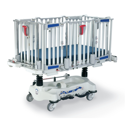
Stryker CUB FL19H Maintenance Manual
Pediatric crib
Hide thumbs
Also See for CUB FL19H:
- Operation manual (42 pages) ,
- Maintenance manual (284 pages) ,
- Manual (196 pages)

Related Manuals for Stryker CUB FL19H


Summary of Contents for Stryker CUB FL19H
- Page 1 C C U U B B ® ® P P e e d d i i a a t t r r i i c c C C r r i i b b M M a a i i n n t t e e n n a a n n c c e e M M a a n n u u a a l l FL19H (1900) 1900-009-002 Rev AA.6 2022-05...
- Page 3 T T a a b b l l e e o o f f C C o o n n t t e e n n t t s s Warning/Caution/Note Definition ..........................4 Summary of safety precautions ..........................4 Introduction for service .............................5 Expected service life ...............................5 Contact information ..............................5...
- Page 4 Upper plastic cover replacement for endrails or siderails with fixed access doors ............48 Lower plastic cover replacement ..........................49 Rail support rolling bearing replacement .........................49 Rail assist cable replacement..........................50 Access door replacement ............................52 Access door upper cover replacement ........................53 Access door lower cover replacement ........................53 Access door hinge replacement ..........................54 Access door release knob replacement ........................54 Access door latch replacement ..........................55...
- Page 5 Defibrillator tray - FA64102 ........................... 139 X-ray cassette holders - FA64069, 3/4 in./FA64076, 1-1/4 in................140 Removable IV pole, 1/2 in., Stryker - FA64135 ....................141 Removable IV pole, 1/2 in. - FDTSH ........................142 Two-stage fixed IV pole - FA64083 ........................
- Page 6 • Always replace the two bolts. The Scotch-Grip coating is less effective after you tighten or remove the bolts. • Always have only Stryker service technicians or service personnel trained by Stryker perform this procedure. Failure to comply can result in serious damage to the bed and or or severe injury to users or patients.
- Page 7 I I n n t t r r o o d d u u c c t t i i o o n n f f o o r r s s e e r r v v i i c c e e This manual assists you with the service of your Stryker product. Read this manual to service this product. This manual does not address the operation of this product.
- Page 8 F F i i x x e e d d e e n n d d r r a a i i l l i i n n s s t t a a l l l l a a t t i i o o n n Always verify proper operation of all components before you return the product to service.
- Page 9 F F i i g g u u r r e e 2 2 – – S S c c a a l l e e c c o o n n t t r r o o l l p p a a n n e e l l P P r r o o c c e e d d u u r r e e 1.
- Page 10 15. "10° " appears on the display. With the product still in the maximum Trendelenburg position, place the weight(s) at the foot end of the litter, in the center, and wait five seconds. Press W W e e i i g g h h / / O O n n (E). 16.
- Page 11 Remove product from service before you perform the preventive maintenance inspection. Check all items listed during annual preventive maintenance for all Stryker Medical products. You may need to perform preventive maintenance checks more often based on your level of product usage. Service only by qualified personnel.
- Page 12 Product serial number: Completed by: Date: G G r r e e a a s s e e p p o o i i n n t t s s 1. Apply OG2 grease (M0027) to the brake bar rod surface (A) (Figure 3). F F i i g g u u r r e e 3 3 –...
- Page 13 S S c c a a l l e e s s y y s s t t e e m m e e r r r r o o r r c c o o d d e e s s E E r r r r o o r r c c o o d d e e E E r r r r o o r r d d e e f f i i n n i i t t i i o o n n R R e e c c o o m m m m e e n n d d e e d d a a c c t t i i o o n n...
- Page 14 E E r r r r o o r r c c o o d d e e E E r r r r o o r r d d e e f f i i n n i i t t i i o o n n R R e e c c o o m m m m e e n n d d e e d d a a c c t t i i o o n n Error - E15 The analog-to-digital converter (ADC)
- Page 15 • Do not place unprotected circuit boards on the floor. N N o o t t e e - - Always ship the circuit boards back to Stryker. Use the antistatic bag that the new board was originally shipped in.
- Page 16 F F i i g g u u r r e e 5 5 – – 7. Reverse steps to reinstall. 8. Verify proper operation before you return the product to service. C C a a s s t t e e r r r r e e p p l l a a c c e e m m e e n n t t , , h h y y d d r r a a u u l l i i c c b b a a s s e e T T o o o o l l s s r r e e q q u u i i r r e e d d : : •...
- Page 17 F F i i g g u u r r e e 6 6 – – C C a a s s t t e e r r a a s s s s e e m m b b l l y y r r e e p p l l a a c c e e m m e e n n t t 8.
- Page 18 9. Using a 1/2” combination wrench, remove the locknut (G) that secures the spring hook to the bolt (Figure 7). Save the locknut. 10. Using two 1/2” combination wrenches, remove the two locknuts (J), four shoulder spacers, and two bolts (H) that secure the top part of the counter lever to both fifth wheel torsion levers (Figure 7).
- Page 19 7. Using a 1/2” combination wrench and 1/2” socket, remove the four locknuts (B) and four bolts (A) that secure the fifth wheel assembly to the support plates (C, M) (Figure 8). Lower the assembly to the ground and remove the assembly from underneath the base frame.
- Page 20 4. Separate the V V e e l l c c r r o o ® fasteners that secure the base hood to the base. 5. Using bungee cords, support the base hood. 6. Using two 1/2” combination wrenches, remove the locknut (C) and bolt (B) that secure the caster (A) to the wheel arms (Figure 9).
- Page 21 A - A A - A F F i i g g u u r r e e 1 1 0 0 – – N N e e u u t t r r a a l l g g u u i i d d e e p p l l a a t t e e r r e e p p l l a a c c e e m m e e n n t t 7.
- Page 22 • (2) Bungee cords (or equivalent) • OG2 grease (M0027) P P r r o o c c e e d d u u r r e e : : 1. Raise the litter and the rails to the highest position. 2.
- Page 23 B B r r a a k k e e a a d d j j u u s s t t m m e e n n t t , , h h y y d d r r a a u u l l i i c c b b a a s s e e T T o o o o l l s s r r e e q q u u i i r r e e d d : : •...
- Page 24 • 9/16” socket • 1/2” combination wrench • 9/16” combination wrench • Spring compression tool (1210-001-003) • OG2 grease (M0027) P P r r o o c c e e d d u u r r e e : : 1.
- Page 25 7. Using a 3/4” socket, slowly turn the fill plug (located on the side of the reservoir) counter-clockwise to allow excess system pressure to vent. Remove and save the fill plug. 8. The hydraulic fluid should be visible at the bottom of the hole. If the fluid cannot be seen, add M M o o b b i i l l ™ Aero HFA hydraulic fluid until the fluid level reaches the bottom of the hole.
- Page 26 8. Remove the bungee cords and replace the base hood. 9. Verify proper operation before you return the product to service. R R e e m m o o v v i i n n g g e e x x c c e e s s s s a a i i r r f f r r o o m m t t h h e e h h y y d d r r a a u u l l i i c c s s y y s s t t e e m m , , h h y y d d r r a a u u l l i i c c b b a a s s e e T T o o o o l l s s r r e e q q u u i i r r e e d d : : •...
- Page 27 • 1/4” hex bit socket • Stiff wire with bent, pointed end • 1/2” diameter rod P P r r o o c c e e d d u u r r e e : : 1. Raise the rails to the highest position. 2.
- Page 28 9. Install the new P.C. valve. Moisten the O-ring seal with hydraulic fluid to ensure a tight seal. 10. Tighten the valve by hand. Using a 13/16” combination wrench, add an additional 1/8” - 1/4” turn. 11. Pump the jack to the highest height. Apply weight to the product and make sure that the jack holds. Verify there are no hydraulic leaks.
- Page 29 P P r r o o c c e e d d u u r r e e : : 1. Raise the litter and the rails to the highest position. 2. Apply the brakes. 3. Using a floor jack, raise the side of the product with the pedal that needs repair approximately four inches off the floor. 4.
- Page 30 A A c c c c e e s s s s o o r r y y b b r r a a c c k k e e t t c c o o v v e e r r r r e e p p l l a a c c e e m m e e n n t t , , s s c c a a l l e e o o p p t t i i o o n n T T o o o o l l s s r r e e q q u u i i r r e e d d : : •...
- Page 31 2. Raise the siderails to the highest position. 3. Lift the foot section and fold it toward the head end of the product. 4. Using a #2 Phillips screwdriver, remove the seven screws that secure the foot cover plate to the litter frame (Figure 16). Remove and save the cover plate.
- Page 32 F F i i g g u u r r e e 1 1 6 6 – – F F o o o o t t c c o o v v e e r r r r e e m m o o v v a a l l 4.
- Page 33 N N o o t t e e • Pay attention to the position of the cable ties and the slack of the cable between each cable tie. • Make sure that the load cell has a one inch radius curve at the first point where it is secured when you install new cables ties on the load cell cable.
- Page 34 6. Reverse steps to reinstall. 7. Calibrate the scale system. See Scale system calibration (page 6). 8. Verify proper operation before you return the product to service. B B a a t t t t e e r r y y r r e e p p l l a a c c e e m m e e n n t t , , s s c c a a l l e e o o p p t t i i o o n n C C A A U U T T I I O O N N •...
- Page 35 4. Using two 1/2” combination wrenches, remove the four locknuts (C), four shoulder spacers (H), four washers (J), and four bolts (B) that secure the head section to the two coupling bars (Figure 20). Remove the head section. Save the locknuts, spacers, washers, and bolts.
- Page 36 8. Move the whole assembly slightly toward the center of the product. 9. Using an 11/16” combination wrench, remove the two nuts (K) that secure the threaded end of the cylinder to the bracket (Figure 20). Remove the pneumatic cylinder. Save the nuts. N N o o t t e e - - Apply medium strength thread locker to the two bolts and the two nuts before installation.
- Page 37 8. Reverse steps to reinstall 9. Verify proper operation before you return the product to service. H H e e a a d d s s e e c c t t i i o o n n s s u u p p p p o o r r t t a a r r m m r r e e p p l l a a c c e e m m e e n n t t T T o o o o l l s s r r e e q q u u i i r r e e d d : : •...
- Page 38 P P r r o o c c e e d d u u r r e e : : 1. Raise the head section to the highest position. 2. Lower the rails all the way down. 3. Apply the brakes. 4.
- Page 39 C C A A U U T T I I O O N N - - Always make sure that the sawhorses can support at least 200 lb (91 kg). 4. Using a #2 Phillips screwdriver, remove the 18 screws (A) that secure the lower head (B) and foot (C) cover plates (Figure 25).
- Page 40 3. Using a #2 Phillips screwdriver, remove the 18 screws (A) that secure the lower head (B) and foot (C) cover plates (Figure 25). Remove and save the cover plates. Save the screws. F F i i g g u u r r e e 2 2 5 5 – – L L i i t t t t e e r r r r e e m m o o v v a a l l - - h h y y d d r r a a u u l l i i c c b b a a s s e e 4.
- Page 41 E E n n d d r r a a i i l l c c e e n n t t r r a a l l c c o o l l u u m m n n a a s s s s e e m m b b l l y y r r e e p p l l a a c c e e m m e e n n t t W W A A R R N N I I N N G G - - Always have only Stryker service technicians or service personnel trained by Stryker perform this procedure.
- Page 42 6. Using a #2 Phillips screwdriver, remove the two screws (D) that secure the lower end of the central column to the lower structural member (E) (Figure 27). Save the screws. 7. Using a #1 Phillips screwdriver, remove the eight screws (F) that secure the top half of the upper plastic cover (G) to the bottom half of the upper plastic cover (H) (Figure 27).
- Page 43 E E n n d d r r a a i i l l c c e e n n t t r r a a l l c c o o l l u u m m n n s s p p r r i i n n g g r r e e p p l l a a c c e e m m e e n n t t W W A A R R N N I I N N G G - - Always have only Stryker service technicians or service personnel trained by Stryker perform this procedure.
- Page 44 S S i i d d e e r r a a i i l l c c e e n n t t r r a a l l c c o o l l u u m m n n a a s s s s e e m m b b l l y y r r e e p p l l a a c c e e m m e e n n t t f f o o r r r r a a i i l l s s w w i i t t h h m m o o v v i i n n g g a a c c c c e e s s s s d d o o o o r r s s W W A A R R N N I I N N G G - - Always have only Stryker service technicians or service personnel trained by Stryker perform this procedure.
- Page 45 P P r r o o c c e e d d u u r r e e : : N N o o t t e e - - Always specify if the product is equipped with the double safety lock when you order a central column assembly. Proper warning labels are affixed to assemblies without the double safety lock.
- Page 46 S S i i d d e e r r a a i i l l c c e e n n t t r r a a l l c c o o l l u u m m n n s s p p r r i i n n g g r r e e p p l l a a c c e e m m e e n n t t f f o o r r r r a a i i l l s s w w i i t t h h m m o o v v i i n n g g a a c c c c e e s s s s d d o o o o r r s s W W A A R R N N I I N N G G - - Always have only Stryker service technicians or service personnel trained by Stryker perform this procedure.
- Page 47 T T o o o o l l s s r r e e q q u u i i r r e e d d : : • #1 Phillips screwdriver • #2 Phillips screwdriver • Small regular screwdriver •...
- Page 48 19. Check the stop catch positions and complete steps 19-24 if adjustments are needed. N N o o t t e e - - Proper adjustment centers the stop catches and evenly distributes the load of the rail. If the stop catches are not centered, they will rub against the plastic extrusion.
- Page 49 10. Insert a small screwdriver between the two halves of the upper plastic cover. Separate the two halves. Use caution to avoid scratching the covers or damaging the lower cover snap pins. 11. Lower the rail to the 14 inch locking position. 12.
- Page 50 21. Raise the siderail to the upper position. 22. Using a #2 Phillips screwdriver, remove the two screws (O) that secure the brake shoe cover (S) to the brake shoe support. Remove and save the cover (Figure 29). 23. Using a 1/2” socket, loosen the two locknuts (Q) that secure the brake shoe (R) to the brake shoe support (S). Remove and save the two locknuts (T) that secure the brake shoe support to the frame (Figure 29).
- Page 51 5. Using a 5/32” Allen wrench, remove the two Allen screws (A) that secure the spacer (B) and the hinge (C) of the two access doors to the lower structural member (D) (Figure 32). Save all parts. N N o o t t e e - - Apply medium strength thread locker to the Allen screw threads before installation. 6.
- Page 52 7. Using needle nose pliers, remove the spring pin (D) that secures the rolling bearing (E) (Figure 30). Remove and discard the rolling bearing. Save the spring. 8. Using a 1/8” punch as a guide, insert the spring pin (D) and the new rolling bearing (E) in to the support holes (Figure 30).
- Page 53 7. Using a #2 Phillips screwdriver, remove the two screws (O) that secure the brake shoe cover (P) to the brake shoe support (S). Remove and save the cover (Figure 28). Save the screws. 8. Cut the cable and slowly release the tension on the spring. Remove and discard the cable. N N o o t t e e - - The cable path begins underneath the lower structural member.
- Page 54 A A c c c c e e s s s s d d o o o o r r r r e e p p l l a a c c e e m m e e n n t t T T o o o o l l s s r r e e q q u u i i r r e e d d : : •...
- Page 55 A A c c c c e e s s s s d d o o o o r r u u p p p p e e r r c c o o v v e e r r r r e e p p l l a a c c e e m m e e n n t t T T o o o o l l s s r r e e q q u u i i r r e e d d : : •...
- Page 56 A A c c c c e e s s s s d d o o o o r r h h i i n n g g e e r r e e p p l l a a c c e e m m e e n n t t T T o o o o l l s s r r e e q q u u i i r r e e d d : : •...
- Page 57 A A c c c c e e s s s s d d o o o o r r l l a a t t c c h h r r e e p p l l a a c c e e m m e e n n t t T T o o o o l l s s r r e e q q u u i i r r e e d d : : •...
- Page 58 F F i i x x e e d d h h e e i i g g h h t t b b a a s s e e OL190247 Rev B (Reference only) Torque item 10 to 120 ±20 in-lb Torque item 5 to 120 ±20 in-lb Torque item 3...
- Page 59 I I t t e e m m N N u u m m b b e e r r N N a a m m e e Q Q u u a a n n t t i i t t y y VB15A1O44FT Hex bolt VE30A1O...
- Page 60 F F i i x x e e d d h h e e i i g g h h t t b b a a s s e e w w i i t t h h s s c c a a l l e e o o p p t t i i o o n n OL190246 Rev B (Reference only) Torque item 10 to 120 ±20 in-lb...
- Page 61 I I t t e e m m N N u u m m b b e e r r N N a a m m e e Q Q u u a a n n t t i i t t y y 19-0634 Hood V V e e l l c c r r o o ®...
- Page 62 F F i i f f t t h h w w h h e e e e l l a a s s s s e e m m b b l l y y o o p p t t i i o o n n , , f f i i x x e e d d b b a a s s e e OL190007 Rev K (Reference only) 12,5 T140...
- Page 63 I I t t e e m m N N u u m m b b e e r r N N a a m m e e Q Q u u a a n n t t i i t t y y VB15A1O32 Hex bolt VB15A1O40...
- Page 64 F F i i x x e e d d b b a a s s e e f f r r a a m m e e s s u u p p p p o o r r t t w w i i t t h h o o u u t t s s c c a a l l e e o o p p t t i i o o n n OL190149-XXX Rev E (Reference only) 2 T130 2 T130...
- Page 65 F F i i x x e e d d b b a a s s e e f f r r a a m m e e s s u u p p p p o o r r t t w w i i t t h h s s c c a a l l e e o o p p t t i i o o n n OL190148 Rev H (Reference only) T450 1 T130...
- Page 66 I I t t e e m m N N u u m m b b e e r r N N a a m m e e Q Q u u a a n n t t i i t t y y QE71-0676-F Label, load cell position, foot end, right VB98A1P48...
- Page 67 B B a a s s e e h h o o o o d d w w i i t t h h o o u u t t I I V V c c a a d d d d y y OL190235 Rev 0 (Reference only) I I t t e e m m N N u u m m b b e e r r...
- Page 68 H H y y d d r r a a u u l l i i c c b b a a s s e e a a s s s s e e m m b b l l y y L19-014 Rev C (Reference only) T120 18,58...
- Page 69 T120 I I t t e e m m N N u u m m b b e e r r N N a a m m e e Q Q u u a a n n t t i i t t y y QDF5053 Black bellow VB35A1O24...
- Page 70 I I t t e e m m N N u u m m b b e e r r N N a a m m e e Q Q u u a a n n t t i i t t y y QDF5060 Constant descent hydraulic jack VB18A1P36...
- Page 71 H H y y d d r r a a u u l l i i c c b b a a s s e e b b r r a a k k e e a a s s s s e e m m b b l l y y L19-002 Rev H (Reference only) TO OL190006 T300...
- Page 72 I I t t e e m m N N u u m m b b e e r r N N a a m m e e Q Q u u a a n n t t i i t t y y 19-0485Z Lower brake lever VB15A1O44...
- Page 73 C C o o n n s s t t a a n n t t d d e e s s c c e e n n t t j j a a c c k k a a s s s s e e m m b b l l y y - - Q Q D D F F 5 5 0 0 6 6 0 0 0719-000-683 Rev D (Reference only) I I t t e e m m N N u u m m b b e e r r...
- Page 74 I I t t e e m m N N u u m m b b e e r r N N a a m m e e Q Q u u a a n n t t i i t t y y 0926-020-162 Wear ring 5050-370-100...
- Page 75 J J a a c c k k b b a a s s e e a a s s s s e e m m b b l l y y 5050-370-100 Rev C (Reference only) I I t t e e m m N N u u m m b b e e r r N N a a m m e e Q Q u u a a n n t t i i t t y y...
- Page 76 F F i i f f t t h h w w h h e e e e l l a a s s s s e e m m b b l l y y o o p p t t i i o o n n , , h h y y d d r r a a u u l l i i c c b b a a s s e e OL190006 Rev H (Reference only) T140 TO L19-002...
- Page 77 I I t t e e m m N N u u m m b b e e r r N N a a m m e e Q Q u u a a n n t t i i t t y y 19-0272Z 5th wheel shaft 28-0150Z...
- Page 78 H H y y d d r r a a u u l l i i c c b b a a s s e e f f r r a a m m e e s s u u p p p p o o r r t t w w i i t t h h o o u u t t s s c c a a l l e e o o p p t t i i o o n n OL190146-XXX Rev H (Reference only) 2 T130 1900-009-002 Rev AA.6...
- Page 79 2 T130 T130 I I t t e e m m N N u u m m b b e e r r N N a a m m e e Q Q u u a a n n t t i i t t y y 19-0937P Head end frame support VE30A1O...
- Page 80 H H y y d d r r a a u u l l i i c c b b a a s s e e f f r r a a m m e e s s u u p p p p o o r r t t w w i i t t h h s s c c a a l l e e o o p p t t i i o o n n OL190145 Rev N (Reference only) RIGHT HEAD LEFT HEAD...
- Page 81 I I t t e e m m N N u u m m b b e e r r N N a a m m e e Q Q u u a a n n t t i i t t y y VB35A1O24 Carriage bolt VE30A1O...
- Page 82 H H y y d d r r a a u u l l i i c c b b a a s s e e l l a a b b e e l l s s OL190078-XXX Rev 2 (Reference only) I I t t e e m m N N u u m m b b e e r r N N a a m m e e...
- Page 83 5 5 t t h h w w h h e e e e l l o o p p t t i i o o n n l l a a b b e e l l s s OL190081-XXX Rev 2 (Reference only) I I t t e e m m N N u u m m b b e e r r...
- Page 84 L L i i t t t t e e r r f f r r a a m m e e L19-006 Rev F (Reference only) 2 T35 T6 7 7 T6 T6 7 T35 2 T35 2 I I t t e e m m N N u u m m b b e e r r N N a a m m e e Q Q u u a a n n t t i i t t y y...
- Page 85 S S i i d d e e r r a a i i l l a a s s s s i i s s t t s s y y s s t t e e m m OL190019W Rev L (Reference only) T130 T130...
- Page 86 I I t t e e m m N N u u m m b b e e r r N N a a m m e e Q Q u u a a n n t t i i t t y y VB35A1O24-S Hex bolt 19-0452W...
- Page 87 E E n n d d r r a a i i l l a a s s s s i i s s t t s s y y s s t t e e m m OL190020W Rev L (Reference only) T130 T130 T130...
- Page 88 I I t t e e m m N N u u m m b b e e r r N N a a m m e e Q Q u u a a n n t t i i t t y y 19-0997 Assist system cable VB35A1O24-S...
- Page 89 H H e e a a d d e e n n d d s s t t a a n n d d a a r r d d a a c c c c e e s s s s o o r r y y b b r r a a c c k k e e t t s s OL190089W Rev K (Reference only) T130 T130...
- Page 90 F F o o o o t t e e n n d d s s t t a a n n d d a a r r d d a a c c c c e e s s s s o o r r y y b b r r a a c c k k e e t t s s OL190091W Rev K (Reference only) T130 T130...
- Page 91 S S t t a a n n d d a a r r d d a a c c c c e e s s s s o o r r y y b b r r a a c c k k e e t t s s w w i i t t h h s s c c a a l l e e o o p p t t i i o o n n OL190186W Rev E (Reference only) T75 12 T130 14...
- Page 92 I I t t e e m m N N u u m m b b e e r r N N a a m m e e Q Q u u a a n n t t i i t t y y QDF19-0867 Scale membrane QE71-0680-F...
- Page 93 N N a a m m e e Q Q u u a a n n t t i i t t y y QP19-0357 Bracket cover, left QE71-0346 Label, Stryker QE71-0655-F Label, IV pole QE71-0534-BIL Label, oxygen bottle and IV pole...
- Page 94 I I t t e e m m N N u u m m b b e e r r N N a a m m e e Q Q u u a a n n t t i i t t y y VW10A10 Washer VE30A1O...
- Page 95 H H e e a a d d s s e e c c t t i i o o n n w w i i t t h h s s u u p p p p o o r r t t a a r r m m OL190025 Rev G (Reference only) T130 T130...
- Page 96 I I t t e e m m N N u u m m b b e e r r N N a a m m e e Q Q u u a a n n t t i i t t y y VB15A1O32 Hex bolt VW10A10...
- Page 97 H H e e a a d d s s e e c c t t i i o o n n w w i i t t h h l l i i f f t t a a s s s s i i s s t t OL190024 Rev L (Reference only) 1900-009-002 Rev AA.6...
- Page 98 I I t t e e m m N N u u m m b b e e r r N N a a m m e e Q Q u u a a n n t t i i t t y y VVB0B1N1052 Shoulder screw VW20A10...
- Page 99 I I t t e e m m N N u u m m b b e e r r N N a a m m e e Q Q u u a a n n t t i i t t y y 19-0052P Head section 19-0053P...
- Page 100 F F i i x x e e d d e e n n d d r r a a i i l l s s 19-0799L Rev -/OL190027W Rev - (Reference only) I I t t e e m m N N u u m m b b e e r r N N a a m m e e Q Q u u a a n n t t i i t t y y...
- Page 101 F F i i x x e e d d f f o o o o t t r r a a i i l l , , a a d d j j u u s s t t a a b b l l e e h h e e a a d d r r a a i i l l w w i i t t h h o o u u t t 9 9 i i n n . . d d o o u u b b l l e e s s a a f f e e t t y y l l o o c c k k OL190142-XXX Rev 11 (Reference only) I I t t e e m m N N u u m m b b e e r r...
- Page 102 F F i i x x e e d d f f o o o o t t r r a a i i l l , , a a d d j j u u s s t t a a b b l l e e h h e e a a d d r r a a i i l l w w i i t t h h 9 9 i i n n . . d d o o u u b b l l e e s s a a f f e e t t y y l l o o c c k k 19-0782L Rev 01/OL190013W Rev 01 (Reference only) I I t t e e m m N N u u m m b b e e r r...
- Page 103 A A d d j j u u s s t t a a b b l l e e e e n n d d r r a a i i l l s s w w i i t t h h o o u u t t 9 9 i i n n . . d d o o u u b b l l e e s s a a f f e e t t y y l l o o c c k k OL190138-XXX Rev 02 (Reference only) I I t t e e m m N N u u m m b b e e r r...
- Page 104 A A d d j j u u s s t t a a b b l l e e e e n n d d r r a a i i l l s s w w i i t t h h 9 9 i i n n . . d d o o u u b b l l e e s s a a f f e e t t y y l l o o c c k k 19-0783L Rev 01/OL190021W Rev - (Reference only) I I t t e e m m N N u u m m b b e e r r...
- Page 105 F F i i x x e e d d e e n n d d r r a a i i l l a a s s s s e e m m b b l l y y OL190015 Rev V (Reference only) T120 T4.5...
- Page 106 I I t t e e m m N N u u m m b b e e r r N N a a m m e e Q Q u u a a n n t t i i t t y y VB18A1O36 Hex bolt VVZ7A1E32...
- Page 107 A A d d j j u u s s t t a a b b l l e e e e n n d d r r a a i i l l a a s s s s e e m m b b l l y y OL190010 Rev V (Reference only) T130 T4.5...
- Page 108 I I t t e e m m N N u u m m b b e e r r N N a a m m e e Q Q u u a a n n t t i i t t y y 19-0264P End oval post QPN-19-0647...
- Page 109 S S i i d d e e r r a a i i l l s s w w i i t t h h o o u u t t a a c c c c e e s s s s d d o o o o r r s s a a n n d d 9 9 i i n n . . d d o o u u b b l l e e s s a a f f e e t t y y l l o o c c k k OL190139-XXX Rev 02 (Reference only) I I t t e e m m N N u u m m b b e e r r...
- Page 110 S S i i d d e e r r a a i i l l s s w w i i t t h h a a c c c c e e s s s s d d o o o o r r s s a a n n d d w w i i t t h h o o u u t t 9 9 i i n n . . d d o o u u b b l l e e s s a a f f e e t t y y l l o o c c k k OL190140-XXX Rev 02 (Reference only) I I t t e e m m N N u u m m b b e e r r...
- Page 111 I I t t e e m m N N u u m m b b e e r r N N a a m m e e Q Q u u a a n n t t i i t t y y OL190018 Fixed access door, right OL190019...
- Page 112 S S i i d d e e r r a a i i l l s s w w i i t t h h o o u u t t a a c c c c e e s s s s d d o o o o r r s s a a n n d d w w i i t t h h 9 9 i i n n . . d d o o u u b b l l e e s s a a f f e e t t y y l l o o c c k k 19-0780L Rev 01 (Reference only) I I t t e e m m N N u u m m b b e e r r...
- Page 113 S S i i d d e e r r a a i i l l s s w w i i t t h h a a c c c c e e s s s s d d o o o o r r s s a a n n d d w w i i t t h h 9 9 i i n n . . d d o o u u b b l l e e s s a a f f e e t t y y l l o o c c k k 19-0781L Rev 01/OL190012W Rev - (Reference only) I I t t e e m m N N u u m m b b e e r r...
- Page 114 S S i i d d e e r r a a i i l l c c o o m m m m o o n n c c o o m m p p o o n n e e n n t t s s OL190014 Rev U (Reference only) T120 T4.5...
- Page 115 I I t t e e m m N N u u m m b b e e r r N N a a m m e e Q Q u u a a n n t t i i t t y y VW20A10 Spring washer VB15A1O48FT...
- Page 116 F F i i x x e e d d a a c c c c e e s s s s d d o o o o r r , , r r i i g g h h t t OL190018 Rev - (Reference only) T4.5 I I t t e e m m...
- Page 117 F F i i x x e e d d a a c c c c e e s s s s d d o o o o r r , , l l e e f f t t OL190022 Rev - (Reference only) T4.5 I I t t e e m m...
- Page 118 A A c c c c e e s s s s d d o o o o r r , , l l e e f f t t OL190016 Rev AB (Reference only) 2,14 13,14 T4.5 13,14 T4.5 I I t t e e m m N N u u m m b b e e r r N N a a m m e e...
- Page 119 I I t t e e m m N N u u m m b b e e r r N N a a m m e e Q Q u u a a n n t t i i t t y y VV83A9A24HL Truss head tapping screw QP19-0638-10...
- Page 120 A A c c c c e e s s s s d d o o o o r r , , r r i i g g h h t t OL190017 Rev AB (Reference only) 19,4 T4.5 I I t t e e m m N N u u m m b b e e r r N N a a m m e e Q Q u u a a n n t t i i t t y y...
- Page 121 I I t t e e m m N N u u m m b b e e r r N N a a m m e e Q Q u u a a n n t t i i t t y y QRC19-0336 Compression spring 19-0282W...
- Page 122 C C e e n n t t r r a a l l c c o o l l u u m m n n w w i i t t h h o o u u t t 9 9 i i n n . . d d o o u u b b l l e e s s a a f f e e t t y y l l o o c c k k OL190141-XXX Rev M (Reference only) 18,8 19,8...
- Page 123 I I t t e e m m N N u u m m b b e e r r N N a a m m e e Q Q u u a a n n t t i i t t y y 19-0793Z Truncated fixed stopper 19-0494...
- Page 124 C C e e n n t t r r a a l l c c o o l l u u m m n n w w i i t t h h 9 9 i i n n . . d d o o u u b b l l e e s s a a f f e e t t y y l l o o c c k k OL190026 Rev U (Reference only) 18,8 19,8...
- Page 125 I I t t e e m m N N u u m m b b e e r r N N a a m m e e Q Q u u a a n n t t i i t t y y VVZ7A1E32 Pan head tapping screw 19-0807Z...
- Page 126 A A c c c c e e s s s s d d o o o o r r l l a a b b e e l l c c o o l l o o r r o o p p t t i i o o n n s s , , U U . . S S . . o o n n l l y y C C o o l l o o r r o o p p t t i i o o n n I I t t e e m m N N u u m m b b e e r r...
- Page 127 S S t t r r e e t t c c h h e e r r l l a a b b e e l l i i n n g g OL190234-XXX Rev D (Reference only) 1900-009-002 Rev AA.6...
- Page 128 Q Q u u a a n n t t i i t t y y QE71-0449 Label, head end QE71-0450 Label, foot end QE71-0521-XXX Label, warning QE71-0480 Serial number plate VR11H43 Pop rivet QE71-0446-XXX Label, warning message QE71-0462 Label, product name QE71-0346 Label, Stryker 1900-009-002 Rev AA.6...
- Page 129 O O x x y y g g e e n n b b o o t t t t l l e e r r e e t t a a i i n n i i n n g g c c o o l l l l a a r r - - O O L L 1 1 9 9 0 0 0 0 4 4 5 5 Rev - (Reference only) I I t t e e m m N N u u m m b b e e r r...
- Page 130 C C h h a a r r t t h h o o l l d d e e r r 2 2 i i n n . . - - O O L L 1 1 9 9 0 0 0 0 9 9 8 8 , , r r i i g g h h t t / / O O L L 1 1 9 9 0 0 0 0 9 9 9 9 , , l l e e f f t t Rev C/Rev C (Reference only) T4.5 I I t t e e m m...
- Page 131 I I V V c c a a d d d d y y , , f f i i x x e e d d h h e e i i g g h h t t b b a a s s e e - - O O L L 1 1 9 9 0 0 0 0 4 4 7 7 - - X X X X X X Rev J (Reference only) T120 I I t t e e m m...
- Page 132 I I t t e e m m N N u u m m b b e e r r N N a a m m e e Q Q u u a a n n t t i i t t y y 19-0641 Connecting arm assembly VB15A1O40...
- Page 133 I I V V c c a a d d d d y y , , h h y y d d r r a a u u l l i i c c b b a a s s e e - - O O L L 1 1 9 9 0 0 0 0 4 4 6 6 - - X X X X X X Rev J (Reference only) T120 T120...
- Page 134 I I t t e e m m N N u u m m b b e e r r N N a a m m e e Q Q u u a a n n t t i i t t y y QE71-0504-XXX Label, IV caddy 19-0641...
- Page 135 R R e e t t r r a a c c t t i i n n g g p p r r o o t t e e c c t t i i v v e e t t o o p p - - F F A A 6 6 4 4 0 0 7 7 4 4 - - X X X X X X L64-0041-XXX Rev N (Reference only) I I t t e e m m N N u u m m b b e e r r...
- Page 136 I I t t e e m m N N u u m m b b e e r r N N a a m m e e Q Q u u a a n n t t i i t t y y 19-0684W Protective top post, left 19-0527...
- Page 137 P P r r o o t t e e c c t t i i v v e e t t o o p p w w i i t t h h s s u u p p p p o o r r t t - - F F A A 6 6 4 4 1 1 8 8 3 3 - - X X X X X X L64-109-XXX Rev G (Reference only) I I t t e e m m N N u u m m b b e e r r...
- Page 138 I I t t e e m m N N u u m m b b e e r r N N a a m m e e Q Q u u a a n n t t i i t t y y QP19-0986-05 Mounting structure QDF5092...
- Page 139 S S i i d d e e r r a a i i l l p p a a d d , , f f u u l l l l p p e e r r i i m m e e t t e e r r - - D D M M 6 6 4 4 0 0 8 8 5 5 1900-009-002 Rev AA.6...
- Page 140 U U p p r r i i g g h h t t o o x x y y g g e e n n b b o o t t t t l l e e h h o o l l d d e e r r - - F F A A 6 6 4 4 0 0 8 8 6 6 L64-0051 Rev 03 (Reference only) I I t t e e m m N N u u m m b b e e r r...
- Page 141 D D e e f f i i b b r r i i l l l l a a t t o o r r t t r r a a y y - - F F A A 6 6 4 4 1 1 0 0 2 2 L64-0056 Rev E (Reference only) I I t t e e m m N N u u m m b b e e r r...
- Page 142 X X - - r r a a y y c c a a s s s s e e t t t t e e h h o o l l d d e e r r s s - - F F A A 6 6 4 4 0 0 6 6 9 9 , , 3 3 / / 4 4 i i n n . . / / F F A A 6 6 4 4 0 0 7 7 6 6 , , 1 1 - - 1 1 / / 4 4 i i n n . . 3/4”...
- Page 143 N N u u m m b b e e r r N N a a m m e e Q Q u u a a n n t t i i t t y y QDF9165 Stryker 1/2 in. removable IV pole 1900-009-002 Rev AA.6...
- Page 144 R R e e m m o o v v a a b b l l e e I I V V p p o o l l e e , , 1 1 / / 2 2 i i n n . . - - F F D D T T S S H H LC-7300 Rev AA (Reference only) I I t t e e m m N N u u m m b b e e r r...
- Page 145 T T w w o o - - s s t t a a g g e e f f i i x x e e d d I I V V p p o o l l e e - - F F A A 6 6 4 4 0 0 8 8 3 3 OL190093-XXX (head left) Rev AA/OL190094-XXX (foot right) Rev H (Reference only) I I t t e e m m N N u u m m b b e e r r...
- Page 146 T T h h r r e e e e - - s s t t a a g g e e f f i i x x e e d d I I V V p p o o l l e e - - F F A A 6 6 4 4 0 0 8 8 4 4 OL190095-XXX (head left) Rev AA/OL190096-XXX (foot right) Rev H (Reference only) 11/16"...
- Page 147 P P r r e e m m i i u u m m a a c c c c e e s s s s o o r r y y b b r r a a c c k k e e t t s s , , h h e e a a d d e e n n d d , , f f o o o o t t e e n n d d - - F F A A 6 6 4 4 1 1 0 0 7 7 OL190084-XXX (head) Rev 02/OL190085-XXX (foot) Rev 02 (Reference only) Head End Only - FA64105 (OL190084-XXX) HEAD...
- Page 148 Carriage bolt 19-0391P Accessory support, right VE30A1O Nylon hex locknut VW10A10 Flat washer VE30A1N Nylon hex locknut VW10A08 Flat washer QE71-0346 Label, Stryker QE71-0534-XXX Label, oxygen bottle and IV pole 19-0777C Fixed socket 19-0778Z Fixed socket spacer 1900-009-002 Rev AA.6...
- Page 149 I I t t e e m m N N u u m m b b e e r r N N a a m m e e Q Q u u a a n n t t i i t t y y VW20A12 Lock washer VB15A1P40...
- Page 150 R R e e c c y y c c l l i i n n g g p p a a s s s s p p o o r r t t O O L L 1 1 9 9 0 0 1 1 8 8 6 6 W W Rev - I I t t e e m m R R e e c c y y c c l l a a b b l l e e p p a a r r t t...
- Page 152 Stryker Medical 3800 E. Centre Avenue Portage, MI 49002 1900-009-002 Rev AA.6 2022-05 WCR: AA.32...
Need help?
Do you have a question about the CUB FL19H and is the answer not in the manual?
Questions and answers