Table of Contents
Advertisement
N
: This portion of the
document should not appear
on produced Labels or IFUs
Stryker Instruments
(269) 323-7700
(800) 253-3210
DSGN-fm-50366
ev.
Effective:
Dimensions:
Color/Material/Finish:
8.5 inch (width) x 11 inch
Color Graphics on White Background
Booklet
20# Bond or Equivalent
Label Stock:
N/A
Description/Type:
Instructions For Use
Part Number:
5400-050-700
Rev.
N
Page 1 of 1
Advertisement
Table of Contents

Related Manuals for Stryker Core 5400-050-000


Summary of Contents for Stryker Core 5400-050-000
- Page 1 8.5 inch (width) x 11 inch Color Graphics on White Background document should not appear Booklet 20# Bond or Equivalent on produced Labels or IFUs Description/Type: Instructions For Use Stryker Instruments Part Number: Rev. (269) 323-7700 (800) 253-3210 5400-050-700 DSGN-fm-50366 Page 1 of 1...
- Page 2 CORE™ Consolidated Operating Room Equipment Powered Instrument Driver 5400-050-000 Instructions For Use Software Version ENGLISH (EN) 2017-09 5400-050-700 Rev-N www.stryker.com...
-
Page 4: Table Of Contents
To Edit Settings - Radio Frequency Identification (RFID) Handpiece and Cutters .....................34 To Access System Information: ......................................35 To Access Help: ..........................................35 Cleaning and Disinfection ......................................36 Inspection, Testing, and Maintenance ...................................36 Troubleshooting ..........................................36 Storage and Handling ........................................37 Disposal/Recycle ..........................................37 Messages ............................................37 Specifications ..........................................39 www.stryker.com... -
Page 5: List Of Illustrations
Figure 30. Keyboard Screens ......................................32 Figure 31. Modify File Screen ......................................33 Figure 32. Add Handpiece Screen ....................................33 Figure 33. View Handpiece Settings Screen .................................34 Figure 34. Typical Edit Setting Screen ..................................34 Figure 35. System Information Screen ..................................35 Figure 36. Typical Help Screen ......................................35 www.stryker.com... -
Page 6: Compliance Statements
License Agreement. In addition, you agree that you will not use this software in any product other than the Stryker product in which the software was initially installed by Stryker. -
Page 7: Introduction
• A NOTE supplements and/or clarifies procedural information. Contact Information For additional information, including safety information, in-service training, or current literature, contact your Stryker sales representative or call Stryker customer service. Outside the US, contact your nearest Stryker subsidiary. www.stryker.com... -
Page 8: Safety Directives
Failure to comply may lead to infection or cross infection and result in technique used for each patient. Stryker, as a manufacturer, does not patient and/or healthcare staff injury. recommend surgical procedure or technique. -
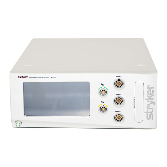
Page 9: System Overview
The console accepts either 100 VAC - 230 VAC input and has the capability to power heavy duty handpieces. The Stryker Firewire Backbone (SFB) serial connection provides a serial communications channel between the console and other devices. This feature allows software upgrades over a computer network. -
Page 10: Hardware Features And Functions
DO NOT modify any component or accessory without the authorization of the manufacturer. NOTE: For a complete list of accessories, contact your Stryker sales representative or call Stryker customer service. Outside the US, contact your nearest Stryker subsidiary. The following Stryker-approved accessories are sold separately: Description Power Cord ......................................... -
Page 11: Operating Instructions
The symbols located on the equipment and/or labeling are defined in this section and/or in the Symbol Definition Chart. See the Symbol Definition Chart supplied with the equipment. SYMBOL DEFINITION SYMBOL DEFINITION SYMBOL DEFINITION On/Off (push-push) Type BF Applied Part Equipotential Footswitch SFB Serial Connection General warning sign Refer to instruction manual/ Handpiece Alternating Current booklet Non-ionizing electromagnetic Irrigation Direct Current radiation www.stryker.com... - Page 12 • If using a CORE Universal Handswitch, attach it to the handpiece before you plug the cord into the handpiece. • If using CORE console software version 6.1 or later, a Heavy Duty Power Pack (power pack) may be used to allow either a Stryker System 4 or 5 Heavy Duty Handpiece to operate with the console.
-
Page 13: Button Definitions
FOOTSWITCH capabilities DISABLE ASSIGN Disable all four NSE Footswitch pads Assign a specific footswitch port to a specific handpiece port BUTTONS FOOTSWITCH TO HANDPIECE SWITCH Toggle between the NSE Footswitch Options screen and the TPS Footswitch Options FOOTSWITCH screen www.stryker.com... - Page 14 INFORMATION information VIEW/EDIT View and edit the user preference file ADJUST Adjust and apply an irrigation flow rate settings of a selected handpiece to a handpiece cutting accessory SETTINGS IRRIGATION PUMP SETTINGS EDIT Change user preference file settings SETTINGS www.stryker.com...
- Page 15 Select German as console screen language GERMAN Deutsch LANGUAGE SELECT Select French as console screen language FRENCH Français LANGUAGE SELECT Select Spanish as console screen language SPANISH Español LANGUAGE SELECT Select Italian as console screen language ITALIAN Italiano LANGUAGE www.stryker.com...
-
Page 16: To Power Up
Instrument Driver XXXX-XXX-XXX X.X_build_X Figure 4. Power Up Screen If no handpieces or cords are connected to the console during initial power up, the following screen will appear (see figure 5): Figure 5. Plug In Handpiece Cable Screen www.stryker.com... -
Page 17: Software Menu Navigation
Preferences Footswitch Folder(s) Language Folders Preference Access Manage User Create New Select Network Set Handpiece Advance Preference Options File(s) Console Connections Files Controls Set Advanced Handpiece Add Handpiece Modify File Options Edit Settings Figure 6. Console Software Menu Map www.stryker.com... -
Page 18: To Select Settings
View Option Settings operated from the same View option settings such as irrigation, footswitch control, and console, simultaneously. fixed or variable RPM (revolutions per minute). All of these settings may be modified. Figure 7. Home Screen - Overview www.stryker.com... -
Page 19: To Adjust Handpiece Speed (Or Power)
Mode HIGH: Touch to cause the handpiece to LOW: Touch to cause the handpiece to operate in the high RPM range mode. operate in the low RPM range mode. Figure 9. Select Mode/Direction Screen www.stryker.com... -
Page 20: To Adjust Options
• Touch the minus button until the TIME-BASED icon is visible to operate in a of deceleration decreases as the setting approaches TIME-BASED mode where the number of turns are based on the speed of zero percent. the handpiece. Figure 10. Adjust Options Screen www.stryker.com... -
Page 21: To Program Footswitch Options
[I, II or III] or pedal [A, B High are handpiece or NSE Footswitch] and Run Mode specific. Touch assign a specific option. the OK button to select the option. Footswitch Options Disable Screen Fwd <> Rev Irrigation on/off Figure 11. Footswitch Options Screens www.stryker.com... - Page 22 5400-050-700 Rev-N To Program Footswitch Options: (continued) WARNING: Read and understand the appropriate Stryker handpiece instructions for use. NOTES: • Footswitch options will override individual handpiece settings unless the footswitch is programmed with default settings. • The following is a generic list of footswitch pedal and pad options that are available if the connected handpiece supports the option:...
-
Page 23: Figure 12. Assign Footswitch Screen - Automatic
Gray indicates no footswitch is assigned to Filled yellow icon with waves indicates which handpiece will be the handpiece port. operated when the associated wireless footswitch is actuated. www.stryker.com... -
Page 24: To Set Handpiece Options
To Set Handpiece Options: WARNING: Read and understand the appropriate Stryker handpiece instructions for use. From the Adjust Options screen, touch the Set Handpiece Options button to select specific handpiece options and assign them to a particular handpiece button (see figure 14). Options are handpiece dependent and may not be available if the handpiece does not support them. -
Page 25: To Set Advanced Handpiece Options
• Touch the button and select OFF to set the torque control to the default setting of 100%. • Touch the button and select ON to allow the torque control to be adjusted between 0% and 100%. Figure 15. Set Advanced Handpiece Options Screen www.stryker.com... -
Page 26: To Select A User Preference Favorite
- Touch to save current Default: Factory Def console settings to the selected file in the user preference favorites list. f1 \ a test \ test1 file \ file2 f1 \ t2 Figure 17. Swap (replace) User Preference Favorite Pop-up www.stryker.com... -
Page 27: Figure 18. Select User Preference Favorite - Folder
Touch the Navigate Select a user preference favorite Up button to return to folder directory. Main / test test1 Touch OK button to replace one of the favorite preference files. Figure 19. Select User Preference Favorite - File www.stryker.com... -
Page 28: To Adjust Irrigation Pump Settings
[0 to 100%]. 23 % Adjust Contrast Touch the slide bar or plus/minus buttons to adjust the percent of console display contrast [0 to 100%]. Figure 21. Adjust Console Options Screen - Standard User Mode www.stryker.com... -
Page 29: To Access Advance User Mode
ADVance User Mode, touch Adjust console options the ADV button Access standard mode again. Touch the OK button if you want to return to the standard user mode. Return to standard mode? Figure 24. Return to Standard User Mode Pop-up www.stryker.com... -
Page 30: To Adjust The Console Options: - Advance User Mode
To Select Advance Console Settings - Advance User Mode Only Touch the button to select network connections. Adjust console options Touch the button to select the console advance settings. Figure 26. Select Advance Console Settings Screen - Advance User Mode www.stryker.com... -
Page 31: To Select Network Connections - Advance User Mode Only
Touch the button to toggle Select network connections network control ON and OFF. Network Control Touch the button to iSWITCH assign a wireless device to a specific footswitch port. Figure 27. Select Network Connections Screen - Advance User Mode www.stryker.com... -
Page 32: To Manage User Preference Folders: - Advance User Mode Only
Current: f1/t2 Main / file Create New File Touch to create a new file. file1 file2 Copy Current Settings Touch to copy the current active user preference settings to a new file. Figure 29. Manage User Preferences Screen - Files www.stryker.com... -
Page 33: To Manage User Preference Folders And Files: - Advance User Mode Only
BACKSPACE Touch to delete keystrokes. ENTER Touch to create folder or file. SHIFT Lock/Unlock Touch to toggle between upper and lower characters. SPACE Touch to create a space between characters and numbers. Figure 30. Keyboard Screens www.stryker.com... -
Page 34: To Modify A File
CORE SAGITTAL SAW CORE U-DRILL CORE U-DRIVER View and Add a Handpiece Touch arrow buttons to scroll through and highlight a handpiece. Touch the ADD button to add a handpiece to the user preference file. Figure 32. Add Handpiece Screen www.stryker.com... -
Page 35: To View Settings
6. Repeat steps 3 through 5 for any additional cutters up to 30 cutters maximum. 7. From the User Preference Favorite screen, touch the SAVE CURRENT SETTINGS button to save all the cutter settings to the selected user preference file. 8. Return to HOME screen and proceed as required. www.stryker.com... -
Page 36: To Access System Information
View Help Topics - Touch the arrow buttons or slider to scroll through and view help topics related to button functions on a specific screen. Figure 36. Typical Help Screen www.stryker.com... -
Page 37: Cleaning And Disinfection
WARNING: DO NOT disassemble, modify, service, or repair this equipment without authorization of the manufacturer. NOTE: For service, contact your Stryker sales representative or call Stryker customer service. Outside the US, contact your nearest Stryker subsidiary. PROBLEM ACTION Console turns off by itself. -
Page 38: Storage And Handling
• ALWAYS store the equipment within the specified environmental condition values throughout its useful life. See the Specifications section. • ALWAYS save the original packaging container for reuse. Failure to comply may result in damage during transport to the Stryker Service Center. - Page 39 INSTRUCTIONAL To enter calibration mode press screen anywhere within 10 seconds NOTE Handpiece requires additional console hardware. Please contact your Stryker representative; or See manual, press OK to clear. NOTE Handpiece requires additional console software. Please contact your Stryker representative; or See manual, press OK to clear.
-
Page 40: Specifications
European Committee for Electrotechnical Standardization (CENELEC) EN 60601-1:2006, Medical Electrical Equipment — Part 1: General Requirements for Basic Safety and Essential Performance; IEC Corrigendum 1 (2006); IEC Corrigendum 2 (2007); CENELEC Corrigendum (2010); CENELEC Amendment A11 (2011) AS/NZS 4268: 2008 www.stryker.com... - Page 41 The CORE Console REF 5400-050-000 is suitable for use in all establishments other than domestic establishments and those directly connected to the public low-voltage power supply network that supplies buildings used for domestic purposes. Harmonic emissions Class A IEC 61000-3-2 Voltage fluctuations/flicker Complies emissions IEC 61000-3-3 www.stryker.com...
- Page 42 Power frequency magnetic fields should be at levels characteristics of a typical location in a typical commercial or hospital environment. (50/60 Hz) @ 50 & 60 Hz magnetic field IEC 61000-4-8 NOTE: U is the a.c. mains voltage prior to application of the test level. www.stryker.com...
- Page 43 RF compliance level above, the CORE Console REF 5400-050-000 should be observed to verify normal operation. If abnormal performance is observed, additional measures may be necessary, such as re-orienting or relocating the CORE Console REF 5400-050-000. Over the frequency range 150 kHz to 80 MHz, field strengths should be less than 3 V/m. www.stryker.com...
- Page 44 NOTE 1: At 80 MHz and 800 MHz, the separation distance for the higher frequency range applies. NOTE 2: These guidelines may not apply in all situations. Electromagnetic propagation is affected by absorption and reflection from structures, objects and people. Trademarks not the property of Stryker Corporation are the property of their respective owners. www.stryker.com...
- Page 45 ES/DE/FR/IT/NL 5400-050-716 JA/ZH/KO 5400-050-724 SV/DA/FI/PT/NO 5400-050-734 PL/EL 5400-050-754 Stryker Instruments 4100 E. Milham Kalamazoo, Michigan (USA) 49001 1-269-323-7700 1-800-253-3210 2017-09 5400-050-700 Rev-N www.stryker.com...
Need help?
Do you have a question about the Core 5400-050-000 and is the answer not in the manual?
Questions and answers