Table of Contents
Advertisement
Available languages
Available languages
Quick Links
Advertisement
Chapters
Table of Contents

Related Manuals for Gima PC-3000


Summary of Contents for Gima PC-3000
- Page 1 ARTICOLI & APPARECCHI PER MEDICINA MONITOR MULTI-PARAMETRICO Manuale d’uso 35134 0476 Gima S.p.A. Via Marconi, 1 - 20060 Gessate (MI) Italy gima@gimaitaly.com - export@gimaitaly.com www.gimaitaly.com Made in China...
-
Page 2: Impostazioni Per La Spo
ITALIANO Prefazione Uso Previsto Questo manuale contiene le istruzioni necessarie per il funzionamento sicuro del prodotto secondo le sue caratteristiche e il suo uso previsto. Per utilizzare correttamente il prodotto e per salvaguardare la sicurezza del paziente e dell’operatore da eventuali infortuni, è fondamentale rispettare le indicazioni contenute in questo manuale. In base alla configurazione massima, alcuni contenuti di questo manuale potrebbero non essere rilevanti per il vostro prodotto. -
Page 3: Table Of Contents
ITALIANO Indice ................................9 Capitolo 1 Sicurezza 1.1 Informazioni in Materia di Sicurezza ........................9 ..............................9 1.1.1 Avvertenze ...............................10 1.1.2 Precauzioni ................................10 1.1.3 Note ............................12 1.2 Simboli del dispositivo ........................12 1.2.1 Simbolo/Icona sul Dispositivo .........................13 1.2.2 Lista delle Icone sullo Schermo Capitolo 2 Informazioni di base ............................14 ............................14... - Page 4 ITALIANO Capitolo 4 Display ................................27 ........................27 4.1 Pagina Elenco Dati Andamento SpO 4.1.1 Descrizione dello Schermo ........................27 ............................27 4.1.2 Istruzioni per l’Uso .............................27 4.2 Pagina Elenco Dati NIBP ........................27 4.2.1 Descrizione dello Schermo ............................28 4.2.2 Istruzioni per l’Uso 4.3 Schermata del grafico di andamento ........................28 ....................28 4.3.1 Come visualizzare il grafico di andamento...
- Page 5 ITALIANO 5.4 Impostazioni di Temperatura ..........................42 ............................... 43 5.5 Impostazioni NIBP 5.6 Impostazioni per la SpO ............................44 ............................44 5.7 Impostazioni Respirazione ................................45 Capitolo 6 Allarmi ............................45 6.1 Categorie di Allarme ..............................45 6.2 Livelli di Allarme 6.3 Indicatori d’allarme ..............................46 ............................46 6.3.1 Spia di allarme...
- Page 6 ITALIANO 8.1 Introduzione ................................. 58 ........................58 8.2 Informazioni in Materia di Sicurezza 8.3 Comprendere il display RESP ..........................58 .........................59 8.4 Modificare le Impostazioni RESP ............................59 Capitolo 9 Monitoraggio NIBP ................................. 59 9.1 Introduzione ................59 9.1.1 La Misurazione Oscillometrica della Pressione Arteriosa 9.1.2 Il Metodo Oscillometrico vs.
- Page 7 ITALIANO 12.3 Schermate con Solo Forme d’Onda ECG ......................72 .........73 12.4 Cinque Canali di Forme d’Onda e Andamenti in Tempo Reale sulla Stessa Schermata 12.5 Schermata Parametri ............................74 Capitolo 13 Batteria ................................. 75 ............................75 13,1 Descrizione Generale ..........................75 13.2 Manutenzione della batteria ..........................76 13.3 Smaltimento della Batteria Capitolo 14 Pulizia e Disinfezione...
- Page 8 ITALIANO 18.2 Eccessiva Interferenza del segnale ECG oppure Linea Base troppo Spessa ............86 ................86 18.3 Nessuna Misura della Pressione Sanguigna o dell’Ossigeno 18.4 Allarme di Sistema .............................87 ............................87 18.5 Problemi all’Allarme ...........................87 18.6 Guasto all’Alimentazione A Informazioni di allarme ..............................87 .........................88 B Stato/Errore durante il monitoraggio C Conformità...
-
Page 9: Capitolo 1 Sicurezza
ITALIANO Capitolo 1 Sicurezza 1.1 Informazioni in Materia di Sicurezza Le dichiarazioni riguardanti la sicurezza presenti in questo capitolo fanno riferimento alle informazioni elementari in materia di sicurezza alle quali l’operatore del monitor è tenuto a prestare attenzione e rispettare. Sono presenti ulteriori dichiarazioni riguardanti la sicurezza in altri capitoli o sezioni, le quali potrebbero essere simili o identiche a quelle che seguono, o specifiche per determinate operazioni. -
Page 10: Precauzioni
ITALIANO poiché potrebbe causare sanguinamenti parziali quando si utilizza il presente monitor la misurazione della pressione sanguigna. Tutti i cavi di collegamento e i tubi delle parti applicate devono essere tenuti lontano dalla cervice del collo del paziente per prevenire il rischio di possibile soffocamento del paziente stesso. Al fine di evitare il rischio di cortocircuiti e di garantire la qualità... - Page 11 ITALIANO componenti e alla descrizione di prodotti per riparazioni effettuate da personale tecnico qualificato. Le funzioni di analisi di aritmie nell’ECG e di monitoraggio del segmento S-T non hanno ricevuto la certificazione CE ☞...
-
Page 12: Simboli Del Dispositivo
ITALIANO 1.2 Simboli del dispositivo 1.2.1 Simbolo/Icona sul Dispositivo Articolo Simbolo/Icona Descrizione Tasto di accensione Tasto derivazione ECG Tasto di silenziamento allarme Tasto Fermoimmagine / Sblocco immagine Avviare/cancellare la misurazione NIBP Tasto vista schermate Indicatore dell’alimentazione CA Indicatore del funzionamento dell’alimentazione Parti applicate di tipo CF a prova di scarica del defibrillatore Avvertenza --- fare riferimento al Manuale d’Uso Parti applicate di tipo BF a prova di scarica del defibrillatore... -
Page 13: Lista Delle Icone Sullo Schermo
ITALIANO La seguente definizione dell’etichetta WEEE si applica soltanto a stati membri della UE. Questo simbolo indica che questo prodotto non deve essere smaltito come un rifiuto domestico. Assicurando il corretto smaltimento del prodotto, si contribuirà ad evitare conseguenze potenzialmente negative per l’ambiente e per la salute umana. -
Page 14: Capitolo 2 Informazioni Di Base
ITALIANO Capitolo 2 Informazioni di base 2.1 Descrizione del Monitor 2.1.1 Nome e Modello del Prodotto Nome del prodotto: Monitor Paziente Modello del Prodotto: Vedere etichetta a pagina I 2.1.2 Uso Previsto Questo Monitor Paziente è uno strumento polifunzionale progettato per monitorare i segni fisiologici vitali di pazienti adulti, bambini e neonati. - Page 15 ITALIANO istantanea dei parametri fisiologici della respirazione. Il bracciale può essere utilizzato anche come laccio, come é adeguato e pratico nell’utilizzo come funzione aggiuntiva, e si possono impostare pressioni differenti del bracciale secondo le condizioni del paziente. Analisi automatica di 20 tipi di aritmia, misurazioni manuali del segmento S-T durante il blocco della forma d’onda ECG o misurazione automatica durante il monitoraggio;...
-
Page 16: Unità Principale
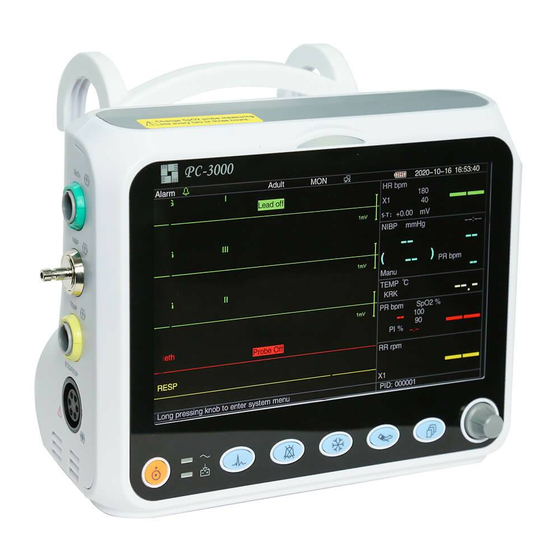
ITALIANO 2.2 Unità Principale Pannello Frontale Figura 2.1 Pulpito Anteriore Nota: L’aspetto del monitor descritto in questo manuale può essere leggermente diverso dal monitor acquistato; per esempio: i tasti operativi possono essere posizionati sulla destra del pannello anteriore. La procedura operativa è... - Page 17 ITALIANO NIBP: Premere per avviare o interrompere la misurazione NIBP. DISP: Cliccare per cambiare la modalità di visualizzazione o per tornare alla Schermata Principale da altre schermate. Premere per cambiare tra Schermata Principale e Schermata 2, configurabile dal Menù di Sistema.
- Page 18 PC come dispositivo di archiviazione e se appare la finestra di pop-up sullo schermo del PC, apparirà un dispositivo di archiviazione removibile chiamato “PC-3000” nella schermata “Questo PC”. Fare doppio click, dopodiché sarà possibile vedere un file dati consultabile in seguito al caricamento dei dati.
-
Page 19: Schermo Di Visualizzazione
ITALIANO 2.3 Schermo di Visualizzazione In generale, quando non compare la finestra di pop-up su schermo, il layout dello schermo del dispositivo include l’area informazioni, l’area forma d’onda e l’area parametri, come mostrato nella figura sottostante. L’area informazioni è in cima alla schermata;... -
Page 20: Area Informazioni
ITALIANO 2.3.1 Area Informazioni L’area informazioni visualizzerà le informazioni relative al paziente (incluso sesso, ID paziente, tipologia paziente e nome), fonti di allarmi fisiologici, stato allarme acustico e data. Stato allarme Tipologia paziente Tipo di filtro ECG Indicatore connessione di rete Data e ora “Alarm ”: Stato allarme acustico, il simbolo verde “... -
Page 21: Area Parametri E Area Forme D'onda
ITALIANO 2.3.2 Area parametri e Area Forme d’onda 1) Area parametri L’area parametri mostra il valore di ogni parametro, l’unità, l’icona, ecc. Spostare la manopola di navigazione per mettere in evidenza un determinato pannello dei parametri (come il pannello dei parametri ECG mostrato nella figura qui sotto), e il pannello verrà... -
Page 22: Capitolo 3 Operazioni
ITALIANO Capitolo 3 Operazioni 3.1 Installazione I dispositivi collegati all’apparecchiatura devono soddisfare i requisiti delle norme IEC applicabili. La configurazione di sistema deve soddisfare i requisiti della norma riguardante i sistemi elettromedicali IEC 60601-1-1. Chi collega dispositivi alla porta di ingresso/uscita dell’apparecchiatura è responsabile di provare che la certificazione di sicurezza dei dispositivi sia stata ottenuta in conformità... -
Page 23: Per Iniziare
ITALIANO corrosive, infiammabili ed esplosive. Se l’apparecchiatura viene installata all’interno di un armadio, deve essere lasciato di fronte e sul retro uno spazio sufficiente a consentirne un comodo utilizzo, la manutenzione e le riparazioni. Inoltre, al fine di mantenere una corretta ventilazione, l’apparecchiatura deve essere mantenuta ad almeno 5 centimetri (2 pollici) dalle pareti dell’armadio. -
Page 24: Accensione Del Monitor
ITALIANO causa dell’insufficiente potenza della batteria. : Indicatore del funzionamento dell’alimentazione; segue descrizione qui sotto. Indicatore Indicatore del dell'alimentazione funzionamento Descrizione dell’alimentazione Il monitor è alimentato dall’alimentazione CA ed è spento Il monitor è alimentato dalla batteria incorporata Stato Il monitor è alimentato dall’alimentazione CA e la batteria è in carica 3.2.2 Accensione del Monitor Il sistema esegue un auto-test e inserisce la visualizzazione iniziale dopo aver acceso il monitor, e un allarme acustico... -
Page 25: Utilizzo Dei Pulsanti
ITALIANO 4. Premere il tasto di accensione/spegnimento sul pannello frontale per spegnere il monitor. Sebbene sia sconsigliabile, è possibile premere e tenere premuto il tasto di accensione/spegnimento per 10 secondi per forzare l’arresto del monitor quando esso non può essere spento normalmente o in determinate situazioni specifiche. -
Page 26: Caricamento Dei Dati
ITALIANO 3.6 Caricamento dei Dati I dati salvati in questo dispositivo possono essere caricati su un computer tramite il cavo USB opzionale per la gestione e la revisione dei dati. Procedura di caricamento dati Fase 1: Scaricare il software per PC “Patient Monitor Data Manager” (gestore dati per monitor paziente) dal sito internet (www.creative-sz.com). -
Page 27: Capitolo 4 Display
ITALIANO Capitolo 4 Display 4.1 Pagina Elenco Dati Andamento SpO Figura 4.1 Schermata di riepilogo dei dati tendenziali della SpO 4.1.1 Descrizione dello Schermo Quando si esegue il monitoraggio, verranno visualizzati i dati più recenti in cima alla lista, inclusi “Time, HR, RR, TEMP, , PR”. -
Page 28: Istruzioni Per L'uso
ITALIANO 4.2.2 Istruzioni per l’Uso È possibile memorizzare fino a 12000 gruppi di dati NIBP. Tramite la Manopola di Navigazione l’utente può scorrere la lista su e giù per visualizzare i dati NIBP. Quando si ruota la manopola in senso antiorario, la lista scorre verso l’alto. Quando si ruota la manopola in senso orario, la lista scorre verso il basso. - Page 29 ITALIANO verso il basso per una migliore vista della curva di andamento. Quando il valore HR supera 150, il massimo valore dell’asse verticale cambierà automaticamente a 300. Infatti il valore sull’asse verticale 0-75-150 cambierà in automatico a 0-150- 300 in caso il valore ECG superi il valore di 150. Quando il monitor viene riavviato o viene cambiato l’ID paziente, l’asse verticale tornerà...
-
Page 30: Istruzioni D'uso
ITALIANO Figura 4.9 Grafico di Andamento Respirazione 4.3.2 Istruzioni d’Uso Ruotare la Manopola di Navigazione per scegliere il parametro e premere la manopola per visualizzare il grafico di andamento. Premere il tasto “ ” per tornare alla Schermata Principale. 4.4 Display Schermata di Richiamo Forma d’Onda Figura 4.10 Schermata di Richiamo Forma d’Onda Mostra che il monitor può... -
Page 31: Istruzioni Per L'uso
ITALIANO Figura 4.11 Richiamo Elenco 4.4.1 Istruzioni per l’Uso Ruotare la “Manopola di Navigazione” e scegliere “Recall” (richiamo)”, “HIST”, “Delete” (cancella) o “Exit” (esci). Le funzioni di ogni tasto sono spiegate qui di seguito. Richiamo: Premere Recall e il primo dato registrato nell’elenco diventerà verde. Ruotare la manopola per scegliere un dato e premere la manopola per richiamarlo. -
Page 32: Schermata Per Elenco Eventi Di Aritmia
ITALIANO 4.5 Schermata per Elenco Eventi di Aritmia Figura 4.13 Schermata Elenco Eventi di Aritmia 4.5.1 Istruzioni per l’Uso Il funzionamento è simile alla schermata di richiamo. I singoli tasti funzione sono descritti qui di seguito. Start: Questo tasto è utilizzato per avviare e arrestare la rilevazione di eventi di Aritmia da parte del sistema. L’impostazione predefinita è... -
Page 33: Schermata Per L'impostazione Del Sistema
ITALIANO Durante il monitoraggio, se si rileva un evento ARR, il monitor andrà in allarme. L’allarme ARR è un default di sistema e non necessario che sia impostato. Durante il rilevamento ARR, può verificarsi un rilevamento scorretto nel caso in cui sia presente un forte segnale di interferenza (es: impulso quadro o triangolare). -
Page 34: Come Modificare Il Colore Dei Parametri
ITALIANO 4.7.1 Come Modificare il Colore dei Parametri Fase 1: ruotare la manopola per spostare il cursore grigio verso l’elemento che si desidera selezionare e premere la manopola per confermare la selezione. Fase 2: ruotare la manopola per scegliere il colore. Fase 3: premere nuovamente la manopola per confermare il colore scelto. -
Page 35: Schermata Oxycrg
ITALIANO disponibile, SAVE sarà visualizzato come OFF Quando l’utente intende salvare in modo permanente la forma d’onda ECG corrente , dovrà eliminare i file storici. Exit: Premere questo tasto per ritornare alla schermata del Menù di Sistema. 4.9 Schermata OxyCRG Figura 4.17 Schermata OxyCRG Questa pagina visualizza il valore o la forma d’onda di HR, SpO , e la forma d’onda RESP o la Velocità... -
Page 36: Descrizione Dello Schermo
ITALIANO 4.10.1 Descrizione dello Schermo La Lista Eventi mostra l’orario, il tipo di evento, il valore individuato e i limiti di allarme superiori e inferiori. L’orario rappresenta l’orario in cui si è verificato l’evento. È possibile visualizzare fino a 5 gruppi di eventi in un’unica schermata. 4.10.2 Istruzioni per il Funzionamento È... - Page 37 ITALIANO Figura 4.20 Schermata di Analisi MC Ruotare la manopola di Navigazione per spostare il cursore all’opzione che deve essere calcolata, premere la manopola e ruotarla per ottenere il valore di calcolo. Quando si seleziona il valore di calcolo, il valore calcolato sarà visualizzato nella posizione corrispondente.
-
Page 38: Funzione Di Laccio Emostatico
ITALIANO 4.12 Funzione di Laccio Emostatico Figura 4.21 Laccio Emostatico “Pressure” (pressione): quando si usa la funzione di Laccio Emostatico, è necessario impostare la pressione del bracciale per l’emostasi. La pressione è regolabile e il suo limite di regolazione varia a seconda della tipologia di paziente: per il neonato: intervallo preimpostato: 70~100 mmHg, valore di default: “90”... -
Page 39: Capitolo 5 Impostazione Parametri
ITALIANO Capitolo 5 Impostazione Parametri Fase 1: ruotare la manopola per spostare il cursore grigio verso l’elemento che si desidera selezionare e premere la manopola per confermare la selezione. Fase 2: ruotare la manopola per modificare l’impostazione o il valore impostato. Fase 3: premere la manopola nuovamente per modificare l’impostazione e premerla nuovamente per confermarla. -
Page 40: Impostazioni Di Rete
ITALIANO “ECG”, il monitor blocca solo la forma d’onda ECG. Quando si seleziona “All”, il monitor blocca tutte le forme d’onda, incluse le forme d’onda ECG, pletismografiche e di respirazione . Il default di fabbrica è “ECG” Disp2: La schermata di visualizzazione alternativa. Opzioni: È possibile selezionare “Obsev” (Osservazione remota) “7 ECG”... -
Page 41: Impostazioni Ecg
ITALIANO monitoraggio centrale. Questo numero varia tra 6001 e 6064. Può anche essere utilizzato per rappresentare il numero del letto del paziente connesso alla stazione di lavoro. Per esempio, il numero di porta 6002 implica che il monitor è assegnato al letto numero 2 nel CSM. La postazione di lavoro può collegare fino a 64 monitor posto letto, per cui si prega di impostare il numero di porta tra 6001 e 6064. -
Page 42: Impostazioni Di Temperatura
ITALIANO Pace (passo): Rilevamento impulso pacemaker cardiaco. Quando Pace è “ON”, la funzione di rilevamento pacemaker sarà attiva. Se il pacemaker genera un impulso regolare quando il paziente lo indossa, verrà visualizzato un segno sulla forma d’onda ECG. L’impostazione di default è OFF. Grid (griglia): La griglia sulla sfondo per la Schermata di osservazione e la schermata di Blocco &... -
Page 43: Impostazioni Nibp
ITALIANO 5.5 Impostazioni NIBP Nella schermata “System Menu”, selezionare “Setup”→“NIBP” per accedere alle impostazioni NIBP. Figura 5.5 Impostazioni NIBP Unit (unità di misura): L’unità di misura della pressione, selezionabile tra mmHg e kPa. Il valore di default è mmHg. Mode: Il modo di misura, manuale o automatico Il default di fabbrica é... -
Page 44: Impostazioni Per La Spo
ITALIANO default: 100 mmHg; per gli adulti: la pressione iniziale di gonfiaggio può essere: 80, 100, 120, 140, 160, 180, 200mmHg, impostazione default: 150 mmHg. Exit (esci): torna alla schermata di Impostazioni del Sistema. 5.6 Impostazioni per la SpO Nella schermata “... -
Page 45: Capitolo 6 Allarmi
ITALIANO Apnea: impostazione della scadenza per l’allarme di apnea. Opzioni: “OFF” e qualunque numero da 5 a 120. Il passo è 1 e la sua unità è il secondo. Quando l’azione di respirazione non è rilevata dopo un tempo più lungo del periodo impostato, la traccia per la forma d’onda di respirazione visualizzerà... -
Page 46: Indicatori D'allarme
ITALIANO Allarme fisiologici Livello di priorità Origine Episodio di Allarme allarme dell’allarme HR oltre il limite, ST oltre il limite, HR oltre l’intervallo, asistolia SpO2 oltre il limite, SpO2 PR oltre il limite, SpO2 oltre l’intervallo Massima Respirazione RR oltre il limite Temperatura TEMP oltre il limite NIBP... -
Page 47: Messaggio Di Allarme
ITALIANO Colore della spia Livello di allarme Rosso lampeggiante Allarme di priorità elevata Giallo Lampeggiante Allarme di media priorità Giallo Allarme a priorità bassa Verde Normale 6.3.2 Messaggio di allarme Quando si verifica un allarme, apparirà un messaggio di allarme nell’area allarmi fisiologici o tecnici. Il messaggio di allarme sarà... -
Page 48: Modificare Il Volume Dell'allarme
ITALIANO 6.3.6 Modificare il Volume dell’Allarme Impostare il volume dell’allarme. Fase 1: Selezionare “System Menu”→“Setup”→“SYS”→“Alarm Volume”. Quando il suono dell’allarme è spento, il monitor non emetterà allarmi uditivi anche nel caso si presenti una nuova situazione di allarme. Per questa ragione, l’utente dovrebbe prestare molta attenzione ed esserne consapevole prima di decidere di spegnere il suono dell’allarme. -
Page 49: Intervallo Di Impostazione Del Limite Di Allarme Superiore E Inferiore
ITALIANO 6.4.1 Intervallo di impostazione del limite di allarme superiore e inferiore Gamma di impostazione Parametro Limite Superiore Limite Inferiore HR(bpm) (Limite inferiore+1)~350 0~(Limite superiore-1) S-T(mV) (Limite inferiore+0,01)~2,50 -2,5~(Limite superiore-0,01) (Limite inferiore+1)~100 0~(Limite superiore-1) (%) PR(bpm) (Limite inferiore+1)~300 0~(Limite superiore-1) RR(rpm)... -
Page 50: Valore Preimpostato Del Limite Di Allarme
ITALIANO 6.4.2 Valore Preimpostato del Limite di Allarme Tipo Adulto Pediatrico Neonato Parametro Limite Superiore 180 bpm 200 bpm 220 bpm Limite Inferiore 40 bpm 50 bpm 50 bpm Limite Superiore 30 rpm 30 rpm 100 rpm Limite Inferiore 8 rpm 8 rpm 30 rpm Limite Superiore... -
Page 51: Capitolo 7 Monitoraggio Ecg
ITALIANO Capitolo 7 Monitoraggio ECG 7.1 Introduzione L’elettrocardiogramma (ECG) è uno strumento utilizzato principalmente per la valutazione dell’attività elettrica del cuore. I segnali ECG vengono rilevati da elettrodi posti sulla superficie della pelle; questo dispositivo connette i segnali ECG e li rappresenta sul monitor come forme d’onda e valori numerici, quali ad esempio la frequenza cardiaca. -
Page 52: Preparazione Al Monitoraggio Ecg
ITALIANO mostrano letture della frequenza cardiaca errata, o attivare un falso allarme. Le possibilità che questa situazione transitoria si verifichi saranno ridotte se gli elettrodi e i cavi sono collegati nelle posizioni idonee come descritto nelle istruzioni del presente manuale. È... -
Page 53: Posizionamento Degli Elettrodi Ecg
ITALIANO 7.3.2 Posizionamento degli Elettrodi ECG Posizionamento degli Elettrodi Le derivazioni ECG e le loro posizioni corrispondenti sono le seguenti: Connessione elettrodo 1 Connessione elettrodo 2 (Standard CEI) (Standard AHA) Posizione elettrodo sulla superficie del corpo Codice colore Etichetta su Codice colore Etichetta su connessione... -
Page 54: Comprendere Il Display Ecg
ITALIANO 7.4 Comprendere il display ECG Il vostro display potrebbe essere configurato in modo da apparire leggermente diverso. forma d’onda ECG “ECG”: etichetta parametro. “III”: Derivazione ECG. III significa derivazione ECG III. “25mm/s”: velocità di scansione forma d’onda ECG; l’unità è “mm/s”. ... -
Page 55: Modificare Le Impostazioni Ecg
ITALIANO “×1/2” Dimensione di mezza scala del guadagno base. “×1” Scala forma d’onda con guadagno base. “×2” Due volte la dimensione di scala del guadagno base. “×4” Quattro volte la dimensione di scala del guadagno base 7.5 Modificare le Impostazioni ECG Vedere la Sezione 5.3 per maggiori dettagli. -
Page 56: Comprendere La Tipologia Di Arr
ITALIANO il segnale ECG sia relativamente privo di disturbi. Se l’apprendimento del modello avviene durante il ritmo ventricolare, il ritmo ectopico potrebbe essere erroneamente interpretato come il normale complesso QRS. Ciò potrebbe risultare in un mancato rilevamento degli episodi conseguenti di V-Tach e V-fib. 7.6.1 Comprendere la Tipologia di ARR Tipo Abbreviazione... -
Page 57: Monitoraggio Del Segmento S-T
ITALIANO 7.7 Monitoraggio del Segmento S-T Alarm (allarme): per attivare o disattivare gli allarmi di superamento limiti di HR e ST, e impostarne i limiti superiore e inferiore. Per impostare l’intervallo, vedere Sezione Allarmi Massimo: Limite inferiore per allarme frequenza cardiaca. Inferiore: limite inferiore per allarme frequenza cardiaca. -
Page 58: Capitolo 8 Monitoraggio Della Respirazione (Resp)
ITALIANO Impostazione scorretta della modalità di filtraggio; Cattiva messa a terra; Elettrodi non correttamente posizionati; Utilizzo di elettrodi scaduti oppure utilizzo ripetuto di elettrodi monouso; La cute su cui è posizionato l’elettrodo non è pulita, oppure vi è un cattivo contatto causato da pelle morta e/o peli;... -
Page 59: Modificare Le Impostazioni Resp
ITALIANO 8.4 Modificare le Impostazioni RESP Vedere la Sezione 5.7 per maggiori dettagli. Capitolo 9 Monitoraggio NIBP 9.1 Introduzione 9.1.1 La Misurazione Oscillometrica della Pressione Arteriosa Questo dispositivo applica la tipica misurazione non invasiva della pressione arteriosa mediante il metodo oscillometrico. Viene utilizzato un bracciale per occludere l’arteria tramite gonfiaggio sopra la pressione sistolica del paziente;... -
Page 60: Restrizioni Alla Misurazione
ITALIANO Quando viene monitorato un paziente adulto, il dispositivo potrebbe non restituire una misurazione della pressione corretta se è selezionata la modalità paziente Bambino. Prima di utilizzare il bracciale, per assicurare una misurazione accurata, vuotarla affinché non ci sia aria residua al ... -
Page 61: Avviare E Arrestare Le Misurazioni
ITALIANO la taglia del bracciale corretta. 3. Collegare il tubo con il bracciale al connettore contrassegnato dall’icona “NIBP” sul pannello di input dei segnali. 4. Scegliere un bracciale che sia della taglia corretta, quindi svolgere il bracciale e avvolgerlo intorno alla parte superiore del braccio del paziente come descritto di seguito: Determinare la circonferenza dell’arto del paziente. -
Page 62: Comprendere I Valori Nibp
ITALIANO rilevare più chiaramente la pulsazione dell’arteria brachiale. 4) il bracciale deve essere serrata in modo tale da consentire l’inserimento di un dito. 5) L’estremità inferiore del bracciale deve trovarsi 2 cm sopra la giunzione del gomito. 2. Il soggetto deve giacere sulla schiena in modo che il bracciale e il cuore siano in posizione orizzontale, così da garantire la misurazione più... -
Page 63: Modificare Le Impostazioni Nibp
ITALIANO 9.7 Modificare le Impostazioni NIBP Vedere la sezione 5.5 per maggiori dettagli. Capitolo 10 Monitoraggio della Saturazione dell’Ossigeno (SpO 10.1 Introduzione La saturazione funzionale dell’ossigeno (SpO ) - una percentuale dell’emoglobina che può trasportare ossigeno, viene monitorata da questo dispositivo tramite una tecnica ottica non invasiva. In base al principio che l’emoglobina ossigenata (HbO ) e l’emoglobina deossigenata (Hb) possiedono un differente carattere di assorbimento nella gamma di spettro tra luce rossa e luce infrarossa il dispositivo misura il quantitativo di emoglobina ossigenata e frequenza del polso tramite... -
Page 64: Applicare Il Sensore
ITALIANO Poiché il valore di SpO serve quale valore di riferimento per la valutazione dell’anossia anemica e tossica, il risultato delle misurazioni di alcuni pazienti affetti da anemia grave possono anche presentare un buon valore di Non applicare nastro adesivo per fissare il sensore alla pelle o per chiuderlo; l’interferenza della pulsazione venosa potrebbe causare imprecisioni nella misurazione della saturazione dell’ossigeno. -
Page 65: Utilizzare La Sonda E Il Sensore
ITALIANO 3. Selezionare un cavo adattatore appropriato in base al tipo di connettore e inserire il cavo nel connettore SpO 4. Connettere il cavo del sensore al cavo adattatore. 10.4 Utilizzare la Sonda e il Sensore Quando si seleziona una sonda o un sensore SpO , è... - Page 66 ITALIANO della mano del paziente. Se necessario, applicare nastro adesivo per fissare il cavo. Tipo 4: Sensore SpO Regolabile di Tipo Y, Neonato Adattatore sensore: avvolgitore Sensore di tipo Y Tipo 5: Sensore SpO di Tipo Y, Neonato Ricevitore (quadrato) Fonte di luce (circolare) Fascia del piede Fascia della caviglia...
-
Page 67: Comprendere Il Display Spo
ITALIANO 10.5 Comprendere il Display SpO e il display PR Pletismogramma: “Pleth”: etichetta che indica l’abbreviazione di pletismografo. Pannello SpO Etichetta della frequenza Etichetta SpO del polso Valore frequenza del Polso Valore SpO Barra dell’intensità della frequenza del polso Limiti di allarme Superiore Etichetta e valore dell’indice e Inferiore per SpO... -
Page 68: Capitolo 11 Monitoraggio Della Temperatura
ITALIANO Capitolo 11 Monitoraggio della Temperatura 11.1 Introduzione La temperatura corporea viene monitorata dalla modalità di misurazione diretta mediante il sensore di temperatura, termiche è un termistore. Un minimo quantitativo di corrente elettrica costante viene applicata al sensore di temperatura per evitare il surriscaldamento;... -
Page 69: Comprendere Il Display Temp
ITALIANO Procedure operative per il trasduttore termico di temperatura: 1. Collegare saldamente il trasduttore al paziente; 2. Collegare il cavo al connettore della sonda TEMP, contrassegnato con “TEMP” nel pannello. 3. Controllare che le impostazioni menu combacino con il tipo di sensore di temperatura utilizzato. 4. -
Page 70: Capitolo 12 Schermata Osservazione Remota
ITALIANO Capitolo 12 Schermata Osservazione Remota 12.1 Schermata da Remoto di Default Premere il tasto DISP per visualizzare la Schermata di Osservazione quando Disp2 è impostato su “Obsev” nella schermata delle impostazioni di sistema, come mostrato nella Figura 13.1. Figura 12.1 Schermata per osservazione da remoto Istruzioni d’Uso: ECG lead (derivazione ECG): premere per spostare il monitoraggio dell’ECG circolatorio tra Ⅰ, Ⅱ... -
Page 71: Schermata Nibp
ITALIANO 12.2 Schermata NIBP Figura 12.2 Visualizzazione Schermata NIBP Premere il tasto DISP per passare dalla schermata principale alla schermata NIBP, come mostrato nella Figura, impostando Disp 2 come “NIBP” in “system menu→system setup→Disp2”. Nella schermata NIBP, il PR da SpO2 viene visualizzato prima del PR da NIBP. -
Page 72: Schermate Con Solo Forme D'onda Ecg
ITALIANO 12.3 Schermate con Solo Forme d’Onda ECG Premere il tasto DISP per passare alla Schermata di Visualizzazione 7 Forme d’onda ECG se l’opzione Disp2 è impostata su “7 ECG” nella schermata delle impostazioni di sistema. In questa schermata l’operatore può visualizzare 7 tracce di forme d’onda ECG contemporaneamente per le derivazioni I, II, III, AVR, AVL, AVF e V, come mostrato nella Figura 2.9. -
Page 73: Cinque Canali Di Forme D'onda E Andamenti In Tempo Reale Sulla Stessa Schermata
ITALIANO 12.4 Cinque Canali di Forme d’Onda e Andamenti in Tempo Reale sulla Stessa Schermata Nota: questa schermata non è disponibile per i monitor senza funzione ECG. Quando l’opzione Disp2 è impostata su “Trend” nella pagina del menù di sistema, il sistema entrerà nella schermata degli andamenti, come indicato nella Figura 12.4. -
Page 74: Schermata Parametri
ITALIANO In questa schermata il primo canale di forma d’onda è la forma d’onda ECG della Derivazione I; il secondo è la forma d’onda ECG della Derivazione III; il terzo è la forma d’onda ECG della Derivazione I; il quarto è la forma d’onda SpO ;... -
Page 75: Capitolo 13 Batteria
ITALIANO Freeze (fermoimmagine): nessuna azione. Premere due volte questo tasto entro 2 secondi per bloccare o sbloccare il funzionamento di tutti gli altri tasti (fatta eccezione per l’interruttore di accensione) sul pannello frontale. NIBP: premere questo tasto per avviare o interrompere la misurazione NIBP. DISP: premere questo tasto per passare alla schermata iniziale. -
Page 76: Smaltimento Della Batteria
ITALIANO o “CE”, oppure contattare direttamente la nostra società. Avvertenze: 1. Per evitare danni alla batteria, rimuovere sempre la/le batteria/e prima di spedizione o stoccaggio. 2. Si raccomanda di utilizzare soltanto batteria specificate dal produttore. 3. La durata del ciclo di vita della batteria dipende dalla frequenza e dalla durata dell’utilizzo a cui è sottoposta. Il ciclo di vita di una batteria piombo-acido o di una batteria al litio è... -
Page 77: Disinfettare Il Dispositivo E Gli Accessori
ITALIANO Non lasciare che il detergente liquido penetri nella presa del connettore del monitor, al fine di evitare danni al dispositivo. Pulire soltanto l’esterno del connettore. Diluire il detergente. Non utilizzare materiali abrasivi. Non lasciare che alcun liquido penetri nella struttura o in qualunque parte del monitor. Non lasciare che il detergente o il disinfettante si depositino sulla superficie. -
Page 78: Capitolo 15 Manutenzione
ITALIANO Capitolo 15 Manutenzione In caso di problemi nel funzionamento del dispositivo, consultare le istruzioni fornite di seguito per eliminare il problema. Se il problema persiste, contattare il proprio fornitore o il produttore. Fare riferimento alle clausole dettagliate nel contratto per quanto riguarda il periodo di garanzia dell’unità principale e degli accessori del monitor. 15.1 Ispezione Quotidiana Prima di utilizzare il monitor, è... -
Page 79: Verifica Del Segnale Ecg
ITALIANO impostare “Make” a “DownLoadMake: KRK”, poi l’utente può utilizzare questa particolare curva R per verificare la funzione SpO . Se il simulatore SpO non contiene la curva R “KRK” , si prega di rivolgersi al produttore per assistenza nello scaricare la curva R data nel simulatore SpO La regolazione delle unità... - Page 80 ITALIANO Metodo 1: Gonfiaggio automatico per la verifica dell’accuratezza della pressione Con questo metodo, il monitor può attivare il gonfiaggio, così che la pressione aumenti automaticamente fino a superare il valore limite specificato nella tabella A. Questo valore limite di pressione dipende dalla selezione della tipologia di paziente, come indicato nella tabella A: Adulto 240 mmHg...
-
Page 81: Accessori
Controllare che gli accessori e il loro imballaggio non presentino segni di danno. Non utilizzarli se viene rilevato un qualsiasi danno. Articolo Descrizione No. materiale Note Set principale PC-3000 Standard Pre-assemblaggio maniglia Standard Sonda SpO per adulti 15044074 Standard... -
Page 82: Resp
ITALIANO 8. Rigetto dell’onda T Alta: Rigetta tutte le onde T inferiori o uguali al 120% di 1mV QRS. 9. Rigetto dell’impulso pacemaker: Rifiuta tutti gli impulsi di ampiezza da ±2mV a ±700mV e di durata da 0,1 a 2 senza oltrepassare;... -
Page 83: Temp
ITALIANO 3. Gamma di impostazione dei limiti di allarme frequenza RESP: Massimo: 1 rpm~150 rpm; Inferiore: 0 rpm~149 rpm. 4. Tolleranza allarme: ±1 rpm 17.3 TEMP 1. Gamma di misurazione TEMP: 21,0℃~50,0 ℃ 2. Precisione di misurazione TEMP: ±0,2 ℃ per la gamma da 25℃ a 45℃, 0,4 ℃ per le altre. 3. -
Page 84: Spo
ITALIANO 17.5 SpO 1. Trasduttore: LED a doppia lunghezza d’onda Lunghezza d’onda: Luce rossa: 660 nm, Luce infrarossa: 905 nm Massima potenza di uscita ottica: meno della media massima, 2mW 2. Gamma di misurazione SpO : 0%~100% 3. Precisione di misurazione di SpO : Lo scarto non è... -
Page 85: Altre Specifiche Tecniche
ITALIANO Modalità Monitoraggio: 0.5~40Hz Modo diagnostico: 0,05~75 Hz 6. Costante di tempo: Modalità Monitoraggio: ≥0,3s Modalità diagnostica: ≥3,2s 17.9 Altre Specifiche Tecniche 1. Alimentazione elettrica: AC100V-240V, 50/60Hz, 60VA; Alimentazione interna (batteria agli ioni di litio): DC 14.8V 2. Modalità di funzionamento: Continua 3. -
Page 86: Stoccaggio
ITALIANO 17.12 Stoccaggio Se l’apparecchiatura non dovrà essere utilizzata per lunghi periodi, pulirla bene e conservarla nell’imballaggio, che dovrà essere mantenuto in un luogo ben ventilato, privo di polvere e di gas corrosivi. Ambiente di stoccaggio: temperatura ambiente: -20~60°C umidità relativa: 10%~95% pressione atmosferica: 53 kPa~106 kPa 17.13 Trasporto Il monitor deve essere trasportato via terra (su strada o ferrovia) o via aria secondo i termini contrattuali. -
Page 87: Nessuna Misura Della Pressione Sanguigna O Dell'ossigeno
ITALIANO 18.3 Nessuna Misura della Pressione Sanguigna o dell’Ossigeno 1. Verificare che il bracciale per la misurazione della pressione sia opportunamente allacciato intorno al braccio del paziente secondo le istruzioni operative, che non vi siano perdite dal bracciale e che l’apposito ingresso con la presa NIBP sul pannello laterale sia collegato correttamente. -
Page 88: A Informazioni Di Allarme
ITALIANO A - Informazioni di allarme Informazione di allarme Descrizione HR oltre il limite RR oltre il limite TEMP oltre il limite oltre il limite PR oltre il limite Il valore del relativo parametro supera il limite preimpostato min/max di allarme. SYS oltre il limite DIA oltre il limite MAP oltre il limite... -
Page 89: C Conformità Emc
ITALIANO “Leak in gas run” Perdite durante la prova del dispositivo pneumatico “System error” Condizione anomala della CPU, quali sovraccarico del registro, diviso per zero Le misurazione della pressione adesso è in modalità adulto. In questo caso, non è “Adult consentito monitorare pazienti bambini o neonati. - Page 90 ITALIANO Tabella 1 Indicazioni e dichiarazione del costruttore - emissioni elettromagnetiche Il dispositivo è destinato a essere utilizzato nell’ambiente elettromagnetico specificato di seguito. Il cliente o l’utente del dispositivo di monitoraggio del paziente deve sincerarsi che questo venga usato in un ambiente con tali caratteristiche.
- Page 91 ITALIANO ±0,5 kV, 1kV da filo(i) a ±0,5 kV, 1kV da filo(i) a La qualità dell’alimentazione di filo(i) filo(i) Sovratensione rete dovrebbe essere quella di un IEC 61000-4-5 tipico ambiente commerciale o ±0,5 kV, ± 1 kV, ±2kV da ±0,5 kV, ± 1 kV, ±2kV da ospedaliero.
- Page 92 ITALIANO Le apparecchiature di comunicazione RF portatili e mobili devono essere utilizzate rispettando la distanza di separazione dalle componenti del dispositivo, cavi inclusi, che può essere calcolata come funzione della frequenza del trasmettitore. RF condotte 0,15 MHz – 80 MHz 0,15 MHz –...
- Page 93 ITALIANO Tabella 4 Gamma di frequenza e livello: apparecchiature RF per comunicazione wireless Livello minimo di Livello di immunità Frequenza di test (MHz) Modulazione immunità (V/m) applicato (V/m) **Modulazione a impulsi: 18Hz *Deviazione FM + 5 Hz: deviazione sinusoidale di 1 kHz **Modulazione a impulsi: 18 Hz **Modulazione a impulsi: 217Hz **Modulazione a impulsi: 18Hz...
- Page 94 Smaltimento: Il prodotto non deve essere smaltito assieme agli altri rifiuti domestici. Gli utenti devono provvedere allo smaltimento delle apparecchiature da rottamare portandole al luogo di raccolta indicato per il riciclaggio delle apparecchiature elettriche ed elettroniche. CONDIZIONI DI GARANZIA GIMA Si applica la garanzia B2B standard Gima di 12 mesi...
- Page 95 PROFESSIONAL MEDICAL PRODUCTS MONITEUR PATIENT MULTIPARAMÈTRES Manuel d’utilisation 35134 0476 Gima S.p.A. Via Marconi, 1 - 20060 Gessate (MI) Italy gima@gimaitaly.com - export@gimaitaly.com www.gimaitaly.com Made in China...
- Page 96 FRANÇAIS Préface Objectif du manuel Les instructions pour un fonctionnement en toute sécurité du produit, conformément à sa fonction et à son utilisation prévue, figurent dans ce manuel. Afin de faire fonctionner correctement le produit et de protéger à la fois le patient et l’opérateur contre les blessures, le respect de ce manuel est très important.
- Page 97 FRANÇAIS Table des matières Chapitre 1 Sécurité ............................... 9 1.1 Informations de sécurité ............................9 ............................9 1.1.1 Avertissements ............................10 1.1.2 Mise en garde ..............................10 1.1.3 Remarques ............................12 1.2 Symboles d’équipement 1.2.1 Symbole / icône sur l’appareil ........................12 1.2.2 Liste des icônes à l’écran ...........................13 .................................
- Page 98 FRANÇAIS 3.5.1 Comment sélectionner un élément du menu ....................25 3.6 Chargement des données ............................26 ............................27 Chapitre 4 Affichage à l’écran .....................27 4.1 Écran de la liste des données de tendance SpO ..........................27 4.1.1 Description de l’écran ..........................27 4.1.2 Instructions d’utilisation 4.2 Écran liste données PNI ............................27 4.2.1 Description de l’écran...
- Page 99 FRANÇAIS 4.12.1 Instructions d’utilisation ..........................38 Chapitre 5 Réglages des paramètres ...........................39 ..........................39 5.1 Réglages paramètres système ............................40 5.2 Réglages liés au réseau ............................41 5.3 Réglages liés à l’ECG ..........................42 5.4 Réglages liés à la température 5.5 Réglages liés au PNI ............................43 5.6 Réglages liés au SpO ............................44...
- Page 100 FRANÇAIS 7.4 Comprendre l’écran ECG .............................54 7.5 Modification des paramètres ECG .........................55 ..............55 7.6 À propos de la détection des arythmies et de l’apprentissage des modèles ........................56 7.6.1 Comprendre le type d’ARR ......................57 7.7 À propos de la surveillance du segment S-T ..............................
- Page 101 FRANÇAIS 10.5 Comprendre l’affiche de la SpO et du pouls .......................67 10.6 Modifier les paramètres de SpO et PR ........................67 Chapitre 11 Surveillance de la température ........................68 ................................ 68 11.1 Introduction ............................68 11.2 Information de sécurité .............................68 11.3 Faire une mesure TEMP 11.4 Comprendre l’affichage TEMP ..........................69 11.5 Modification des Réglage TEMP...
- Page 102 FRANÇAIS 17.3 Pression invasive (TEMP) ..........................83 17.4 PNI ..................................83 ..................................84 17.5 SpO ............................... 84 17.6 Rythme cardiaque ..............................84 17.7 Segment S-T ..........................84 17.8 Enregistrement des données 17.9 Autres spécifications techniques ..........................85 17.10 Classification ..............................85 ...........................85 17.11 Environnement d’exploitation ................................
-
Page 103: Chapitre 1 Sécurité
FRANÇAIS Chapitre 1 Sécurité 1.1 Informations de sécurité Les consignes de sécurité présentées dans ce chapitre se rapportent aux informations de sécurité de base que l’opérateur du moniteur doit respecter. Il existe des déclarations de sécurité supplémentaires dans d’autres chapitres ou sections, qui peuvent être identiques ou similaires aux suivantes ou spécifiques aux opérations. -
Page 104: Mise En Garde
FRANÇAIS Ne désactivez pas l’alarme sonore si la sécurité du patient peut être compromise. Il est interdit au moniteur d’appliquer à ceux qui ont une tendance hémorragique sévère ou qui sont atteints de drépanocytose car ils peuvent développer un saignement partiel lorsque ce moniteur est utilisé pour mesurer la tension artérielle. -
Page 105: Remarques
FRANÇAIS 1.1.3 Remarques ☞ Toutes les combinaisons d’équipements doivent être conformes à la norme CEI 60601--1. ☞ Ne pas positionner l’appareil d’une manière qui rendrait le branchement de la fiche du cordon d’alimentation difficile. ☞ Après le cycle de vie du moniteur et de ses accessoires, la mise au rebut doit être effectuée conformément aux exigences nationales et/ou locales. -
Page 106: Symboles D'équipement
FRANÇAIS 1.2 Symboles d’équipement 1.2.1 Symbole / icône sur l’appareil Élément Symbole/Icône Description Interrupteur Touche principale ECG Touche de silence d’alarme Touche pour figer/débloquer Démarrer/Annuler la mesure NIBP Touche d’affichage écran Indicateur de courant alternatif Indicateur d’alimentation de travail Pièces appliquées de type CF avec protection anti-défibrillation Avertissement --- se référer au manuel d’utilisation Pièces appliquées de type BF avec résistance à... -
Page 107: Liste Des Icônes À L'écran
FRANÇAIS Date de fabrication La définition suivante du label DEEE s’applique uniquement aux États membres de l’UE. Ce symbole indique que ce produit ne doit pas être traité comme un déchet ménager. En veillant à ce que ce produit soit éliminé correctement, il est possible de contribuer à... -
Page 108: Chapitre 2 Les Bases
FRANÇAIS REMARQUE : certains symboles peuvent ne pas apparaitre sur votre appareil Chapitre 2 Les bases 2.1 Description du moniteur 2.1.1 Nom du produit et modèle Nom du produit : Moniteur patient Modèle du produit : voir étiquette à la page I 2.1.2 Utilisation prévue Ce moniteur patient est un instrument multifonctionnel conçu pour surveiller les signes physiologiques vitaux des adultes, des enfants et des nouveau-nés. - Page 109 FRANÇAIS caractères et affiche une trace de la forme d’onde ECG. Sept traces de formes d’onde ECG sur une vue d’écran : affiche 7 traces de formes d’onde ECG pour différentes dérivations et paramètres de surveillance simultanément sur un seul écran. Cinq canaux de formes d’onde en temps réel et deux heures d’affichage des tendances de l’écran : intuitif connaissant l’état physiologique du patient.
-
Page 110: Unité Principale
FRANÇAIS 2.2 Unité principale Panneau avant Figure 2.1 Panneau avant Remarque : L’apparence décrite dans ce manuel peut être légèrement différente avec le moniteur que vous avez acheté, par exemple, les touches de fonctionnement peuvent être situées sur le côté droit du panneau avant. - Page 111 FRANÇAIS Freeze (Figer) : Appuyez sur la touche pour geler/dégeler la forme d’onde ECG ou les formes d’onde ECG, SpO et RESP selon le réglage de l’appareil, et entrez dans l’écran de mesure du segment ST pour l’analyse (sur l’écran d’observation). NIBP (PNI) : Appuyez pour démarrer ou arrêter la mesure PNI.
- Page 112 FRANÇAIS Les ports du câble et du transducteur sont situés dans le panneau de gauche, comme illustré à la Figure 2.2. : Prise du capteur SpO PNI : Connecteur de tube PNI TEMP : Connecteur de capteur TEMP ...
-
Page 113: Écran D'affichage
FRANÇAIS 2.3 Écran d’affichage En règle générale, lorsqu’il n’y a pas de fenêtre contextuelle sur l’écran, la disposition de l’écran de l’appareil comprend la zone d’informations, la zone de forme d’onde et la zone de paramètres, comme illustré dans la figure ci-dessous. La zone d’information est en haut de l’écran, la zone de paramètres est à... -
Page 114: Zone D'informations
FRANÇAIS 2.3.1 Zone d’informations La zone d’informations affiche les informations du patient (y compris le sexe, l’ID du patient, le type et le nom du patient), les sources d’alarme physiologiques, l’état du son d’alarme et la date actuelle. État de l’alarme Type de patient Type de filtre ECG Indicateur de connexion réseau... - Page 115 FRANÇAIS Panneau ECG: pour accéder à la fenêtre de configuration ECG Panneau PNI: pour accéder rapidement à la fenêtre de configuration de PNI Panneau température: pour accéder rapidement à la fenêtre de configuration de TEMP Panneau SpO : pour accéder rapidement à...
-
Page 116: Chapitre 3 Fonctionnement
FRANÇAIS Chapitre 3 Fonctionnement 3.1 Installation Les appareils connectés à l’équipement doivent répondre aux exigences des normes CEI applicables. La configuration du système doit répondre aux exigences de la norme CEI 60601-1-1 relative aux systèmes électriques médicaux. Tout personnel qui connecte des dispositifs au port d’entrée/sortie du signal de l’équipement est tenu de fournir la preuve que la certification de sécurité... -
Page 117: Commencer
FRANÇAIS poussière, de substances corrosives, inflammables et explosives. Si l’équipement est installé dans une armoire, il doit y avoir suffisamment d’espace devant et derrière pour une utilisation, une maintenance et une réparation pratiques. De plus, pour maintenir une bonne ventilation, l’équipement doit être situé à au moins 5 cm (2 po) de l’ensemble de l’armoire. -
Page 118: Allumer Le Moniteur
FRANÇAIS La batterie fournie du moniteur doit être rechargée après le transport ou le stockage. Ainsi, si le moniteur est allumé sans être connecté à l’alimentation secteur, il risque de ne pas fonctionner correctement en raison d’une alimentation insuffisante de la batterie. : L’indicateur d’alimentation de travail et la description sont comme indiqué... -
Page 119: Utilisation Des Touches
FRANÇAIS 2. Débranchez les câbles patient et les capteurs du patient. 3. Assurez-vous de sauvegarder ou d’effacer les données de surveillance selon vos besoins. 4. Appuyez sur la touche Marche/Arrêt du panneau avant pour éteindre le moniteur. Bien que cela ne soit pas recommandé, vous pouvez appuyer sur la touche Marche / Arrêt pendant 10 secondes ... -
Page 120: Chargement Des Données
FRANÇAIS 3.6 Chargement des données Les données stockées dans cet appareil peuvent être téléchargées sur l’ordinateur via le câble de données USB fourni en option pour la gestion et l’examen des données. Procédure de chargement des données Étape 1 : Téléchargez le logiciel PC « Gestionnaire de données du moniteur patient » à partir du site web (www.creative- sz.com). -
Page 121: Chapitre 4 Affichage À L'écran
FRANÇAIS Chapitre 4 Affichage à l’écran 4.1 Écran de la liste des données de tendance SpO Figure 4.1 Écran de la liste des données de tendance SpO 4.1.1 Description de l’écran Lors de la surveillance, les données les plus récentes seront affichées en haut de la liste, y compris « Heure, HR, RR, TEMP, , PR”. -
Page 122: Instructions D'utilisation
FRANÇAIS 4.2.2 Instructions d’utilisation Jusqu’à 12 000 groupes de données NIBP peuvent être mémorisés. L’utilisation du bouton de navigation permet à l’utilisateur de faire défiler la liste vers le haut et le bas pour afficher les données PNI. Lorsque vous tournez le bouton dans le sens inverse des aiguilles d’une montre, la liste défile vers le haut. - Page 123 FRANÇAIS (300). Le graphique est réduit pour une meilleure vue de la courbe de tendance. Lorsque la valeur HR dépasse 150, la valeur maximale de l’axe vertical passe automatiquement à 300. En d’autres termes, la valeur de l’axe vertical 0-75-150 passera automatiquement à...
-
Page 124: Écran D'affichage De Rappel Forme D'onde
FRANÇAIS Figure 4.9 Graphique de tendance respiration 4.3.2 Instructions d’utilisation Tournez le bouton de navigation pour choisir le paramètre et appuyez sur le bouton pour examiner le graphique de tendance. Appuyer sur la touche « » pour retourner au menu principal. 4.4 Écran d’affichage de rappel forme d’onde Figure 4.10 Écran de rappel de forme d’onde Il montre que la surveillance peut rappeler les données d’historique en continu. - Page 125 FRANÇAIS Figure 4.11 Liste des rappels 4.4.1 Instructions d’utilisation Tournez le « bouton de navigation » et choisissez « Rappel », « HIST », « Supprimer » ou « Quitter ». Nous expliquons les fonctions de chaque bouton ci-dessous. Rappel : Appuyez sur Rappel et le premier enregistrement de la liste de rappel devient vert. Tournez le bouton pour choisir un enregistrement et appuyez sur le bouton pour le rappeler.
-
Page 126: Écran D'affichage Liste Évènements D'arythmie
FRANÇAIS 4.5 Écran d’affichage liste évènements d’arythmie Figure 4.13 Écran liste évènements d’arythmie 4.5.1 Instructions d’utilisation La structure est similaire à l’écran de rappel. Nous couvrirons chaque touche de fonction ci-dessous. Start : Ce bouton est utilisé pour démarrer et arrêter la détection d’arythmie du système. La valeur par défaut est OFF. Lorsque l’arythmie n’est pas activée, la touche «... -
Page 127: Affichage À L'écran Pour Le Réglage Du Système
FRANÇAIS Pendant la surveillance, si un événement ARR est détecté, le moniteur émettra une alarme. L’alarme ARR est la valeur par défaut du système et n’a pas besoin d’être configurée. Pendant la détection ARR, une détection incorrecte peut se produire si le signal d’interférence important (par exemple, une impulsion carrée ou une impulsion triangulaire) apparaît. -
Page 128: Comment Changer Le Réglage Couleur
FRANÇAIS 4.7.1 Comment changer le réglage couleur Étape 1 : tournez le bouton pour déplacer le curseur gris sur l’élément de réglage et appuyez sur le bouton pour confirmer votre sélection. Étape 2 : tournez le bouton pour choisir la couleur. Étape 3 : appuyez à... -
Page 129: Écran Oxycrg
FRANÇAIS d’enregistrer la forme d’onde ECG actuelle de manière permanente, veuillez supprimer les fichiers d’historique. Exit : Appuyez sur cette touche pour revenir à l’écran du menu système. 4.9 Écran OxyCRG Figure 4.17 Écran OxyCRG Cet écran affiche la valeur ou la forme d’onde de HR, SpO , et la forme d’onde RESP ou la fréquence respiratoire dans le temps sélectionné. -
Page 130: Description De L'écran
FRANÇAIS 4.10.1 Description de l’écran La liste d’événements affiche l’heure, le type d’événement, la valeur détectée et les limites d’alarme haute et basse. L’heure indique l’heure à laquelle l’événement s’est produit. Jusqu’à 5 groupes de données d’événement peuvent être affichés sur un seul écran. 4.10.2 Instructions d’utilisation Jusqu’à... - Page 131 FRANÇAIS Sur l’écran de calcul du médicament, l’opérateur doit d’abord déplacer le curseur gris sur « Medecine » pour sélectionner le nom du médicament calculé, puis déplacer le curseur sur « Weight » pour sélectionner et confirmer le poids du patient, à...
-
Page 132: Fonction Tourniquet
FRANÇAIS 4.12 Fonction Tourniquet Figure 4.21 Tourniquet « Pressure » (Pression) : lorsque vous utilisez la fonction Tourniquet, vous devez prérégler une pression du brassard pour l’hémostasie. La pression est réglable et sa limite de réglage est différente selon le type de patient : pour les nouveau-nés : plage prédéfinie : 70~100 mmHg, valeur par défaut : «... -
Page 133: Chapitre 5 Réglages Des Paramètres
FRANÇAIS Chapitre 5 Réglages des paramètres Étape 1 : tournez le bouton pour déplacer le curseur gris sur l’élément de réglage et appuyez sur le bouton pour confirmer votre sélection. Étape 2 : tournez le bouton pour changer le réglage ou modifier la valeur de réglage. Étape 3 : appuyez à... -
Page 134: Réglages Liés Au Réseau
FRANÇAIS Frze : Appuyez sur la touche pour figer les formes d’onde sélectionnées. Les options sont « All » et « ECG ». Lorsque « ECG » est sélectionné, le moniteur fige uniquement la forme d’onde ECG. Lorsque « All » est sélectionné, le moniteur fige toutes les formes d’onde, y compris l’ECG, le pléthysmogramme et la forme d’onde de respiration. -
Page 135: Réglages Liés À L'ecg
FRANÇAIS patient se connectant au poste de travail. Par exemple, le numéro de port 6002 signifie que le moniteur est affecté au numéro de lit 2 du CSM. Le poste de travail peut se connecter à jusqu’à 64 moniteurs de chevet, veuillez donc définir le numéro de port entre 6001 et 6064. -
Page 136: Réglages Liés À La Température
FRANÇAIS génère une impulsion de stimulation lorsque le patient porte un stimulateur cardiaque. La valeur d’usine par défaut est OFF. Grid : La grille en arrière-plan pour l’écran d’observation et l’écran d’analyse Frozen et S-T. La valeur d’usine par défaut est OFF. -
Page 137: Réglages Liés Au Pni
FRANÇAIS 5.5 Réglages liés au PNI Sur l’écran « System Menu », sélectionnez « Setup »→« NIBP » (PNI) pour entrer dans les paramètres relatifs au PNI. Figure 5.5 Réglages liés au PNI Unit : On peut sélectionner l’unité de pression en mmHg et kPa. La valeur d’usine par défaut est mmHg. Mode : Le mode de mesure, manuel ou automatique. -
Page 138: Réglages Liés Au Spo
FRANÇAIS pour les enfants : la pression de gonflage initiale peut être : 80, 100, 120, 140 mmHg, valeur par défaut :100 mmHg ; pour les adultes : la pression de gonflage initiale peut être : 80, 100, 120, 140, 160, 180, 200mmHg, valeur par défaut : 150 mmHg. -
Page 139: Chapitre 6 Alarmes
FRANÇAIS Apnea : réglage du délai d’attente pour l’alarme d’apnée. Options : « OFF » et tout nombre de 5 à 120. Le pas est 1 et son unité est deuxième. Lorsque l’action respiratoire n’est pas détectée après un laps de temps supérieur à cette période définie, le tracé... -
Page 140: Indicateurs D'alarme
FRANÇAIS et l’alarme technique. Alarme physiologique Source Niveau de priorité Événement d’alarme d’alarme d’alarme FC au-dessus de la limite, ST au-dessus de la limite, FC au-dessus de la plage, asystolie SpO2 au-dessus de la limite, SpO2 PR au-dessus de la limite, SpO2 au- dessus de la plage Haute Respiration... -
Page 141: Lampe D'alarme
FRANÇAIS 6.3.1 Lampe d’alarme Couleur lampe Niveau d’alarme Clignotant rouge Alarme de haute priorité Clignotant jaune Alarme de priorité moyenne Jaune Alarme de basse priorité Vert Normal 6.3.2 Message d’alarme Lorsqu’une alarme se produit, un message d’alarme apparaîtra dans la zone d’alarme technique ou physiologique. Et le message d’alarme est affiché... -
Page 142: Modification Du Volume D'alarme
FRANÇAIS est en pause, elle affiche le compte à rebours, sinon elle affiche la date. Déplacer le curseur sur cette zone d’affichage du texte peut faire apparaître la boîte de saisie du réglage “Volume de l’alarme“. 6.3.6 Modification du volume d’alarme Pour régler le volume sonore de l’alarme. -
Page 143: Plage De Réglage D'alarme Haute Et Basse
FRANÇAIS 6.4.1 Plage de réglage d’alarme haute et basse Plage de réglage Paramètre Limite haute Limite basse HR(bpm) (Limite basse+1)~350 0~(Limite haute-1) S-T(mV) (Limite basse +0.01)~2.50 -2.5~( Limite hausse -0.01) (Limite basse +1)~100 0~(Limite haute-1) (%) PR(bpm) (Limite basse +1)~300 0~(Limite haute-1) RR(rpm)... -
Page 144: Valeur De Réglage De La Limite D'alarme Par Défaut
FRANÇAIS 6.4.2 Valeur de réglage de la limite d’alarme par défaut Type Adulte Enfant Nouveau-né Valeurs Limite haute 180 bpm 200 bpm 220 bpm Limite basse 40 bpm 50 bpm 50 bpm Limite haute 30 rpm 30 rpm 100 rpm Limite basse 8 rpm 8 rpm... -
Page 145: Chapitre 7 Surveillance De L'ecg
FRANÇAIS Chapitre 7 Surveillance de l’ECG 7.1 Introduction L’électrocardiogramme (ECG) est avant tout un outil d’évaluation des événements électriques dans le cœur. Les signaux ECG peuvent être détectés par des électrodes à la surface de la peau, cet appareil connecte les signaux ECG et les représente sur le moniteur sous forme de signaux et de valeurs numériques telles que la fréquence cardiaque. -
Page 146: Préparation À La Surveillance De L'ecg
FRANÇAIS Ce moniteur patient peut résister à la décharge du défibrillateur et aux interférences de l’unité électro-chirurgicale. Les lectures peuvent être imprécises pendant une courte période après ou pendant l’utilisation du défibrillateur ou de l’unité électrochirurgicale. Les transitoires provoqués par les circuits des câbles lors de la surveillance peuvent provoquer des artefacts sur ... -
Page 147: Placement Des Électrodes Ecg
FRANÇAIS Le symbole indique que le câble et les accessoires sont conçus comme des capteurs de type «CF» pour la protection contre les chocs électriques et la capacité de protection contre les défibrillations. 7.3.2 Placement des électrodes ECG Placement des élécrodes Les dérivations ECG et leurs emplacements correspondants sont les suivants : Connexion d’électrode 1 Connexion d’électrode 2... -
Page 148: Comprendre L'écran Ecg
FRANÇAIS 7.4 Comprendre l’écran ECG Votre affichage peut être configuré pour être légèrement différent. Forme d’onde ECG « ECG » : étiquette paramètre. I“III“ : dérivation ECG. III signifie dérivation ECG III. « 25mm / s » : vitesse de balayage de la courbe ECG, l’unité est « mm/s ». ... -
Page 149: Modification Des Paramètres Ecg
FRANÇAIS « ×1/4 » Échelle 1/4 du gain de base. « ×1/2 » Échelle 1/2 du gain de base. « ×1 » Échelle de la forme d’onde avec gain de base. « ×2 » Deux fois l’échelle du gain de base. «... -
Page 150: Comprendre Le Type D'arr
FRANÇAIS 7.6.1 Comprendre le type d’ARR Type Abréviation Nom complet ECG TACHY Tachycardie ECG BRADY Bradycardie ARRET ECG Arrêt cardiaque BATTEMENT MANQUANT BATTEMENT MANQUANT VE TÔT Contraction Ventriculaire Prématurée (VPC) SVE TÔT Contraction prématurée ventriculaire (SVPC) VE COUPLET Couplet ventriculaire SVE COUPLET Couplet supraventriculaire VE RUN... -
Page 151: À Propos De La Surveillance Du Segment S-T
FRANÇAIS 7.7 À propos de la surveillance du segment S-T Alarme : pour activer ou désactiver les alarmes de dépassement des limites de HR et S-T, et définir leurs limites d’alarme haute et basses. Plage de réglage Voir Section Alarmes ... -
Page 152: Chapitre 8 Surveillance De La Respiration (Resp)
FRANÇAIS Les électrodes ne sont pas placées correctement ; Utiliser une électrode périmée ou utiliser une électrode jetable à plusieurs reprises ; L’électrode placée sur la peau est mal nettoyée ou contractée par les pellicules et les cheveux ; Chapitre 8 Surveillance de la respiration (RESP) 8.1 Introduction La respiration est surveillée en mesurant l’impédance à... -
Page 153: Modification Des Paramètres Du Resp
FRANÇAIS 8.4 Modification des paramètres du RESP Voir Section 5.7 pour plus de détails. Chapitre 9 Surveillance de la PNI 9.1 Introduction 9.1.1 Mesurer la pression artérielle oscillométrique Cet appareil applique la mesure typique de la pression artérielle non invasive avec la méthode oscillométrique. Un brassard est utilisé... -
Page 154: Limites De Mesure
FRANÇAIS Lorsqu’un patient adulte est surveillé, l’appareil peut ne pas donner la mesure de la pression artérielle si le type de patient pédiatrique est sélectionné. Avant d’utiliser le brassard, videz le brassard jusqu’à ce qu’il n’y ait plus d’air résiduel à l’intérieur pour assurer ... -
Page 155: Mesures De Démarrage Et D'arrêt
FRANÇAIS 2. Vérifiez la zone d’information du patient à l’écran. Définissez un type de patient correct, sélectionnez une taille de brassard correcte. 3. Connectez le tube avec le brassard au connecteur portant l’icône “NIBP“ sur le panneau d’entrée du signal. 4. -
Page 156: Comprendre Le Numérique Nibp
FRANÇAIS 2) Ne pas oublier d’éliminer l’air résiduel dans le brassard avant de commencer la mesure. 3) Positionner le brassard de manière à ce que la marque de l’artère « » se trouve à un endroit où le pouls de l’artère brachiale est le plus facilement perceptible. -
Page 157: Modification Des Paramètres Pni
FRANÇAIS « Manu » : l’icône du mode de mesure de la pression non-invasive. Il existe 3 modes : « Manual », « Auto » et « STAT ». En mode “AUTO“, un compte à rebours est également affiché. 9.7 Modification des paramètres PNI Voir section 5.5 pour plus de détails. -
Page 158: Appliquer Le Capteur
FRANÇAIS double lumière rubis, un chauffage infrarouge et la lumière directe du soleil, etc. Comme la valeur de la SpO sert de valeur de référence pour juger de l’anoxie anémique et de l’anoxie toxique, le résultat des mesures de certains patients souffrant d’anémie grave peut également présenter une bonne valeur de SpO Ne pas appliquer de ruban adhésif pour fixer le capteur en place ou pour le scotcher. -
Page 159: Utilisation De La Sonde Et Du Capteur
FRANÇAIS 1. Sélectionner un capteur et une sonde appropriés en fonction du type de module et de la catégorie de patient. 2. Appliquer le capteur sur le site approprié du patient. 3. Choisir un câble adaptateur approprié en fonction du type de connecteur et brancher ce câble sur le connecteur de 4. - Page 160 FRANÇAIS (B) Insérez le doigt du patient dans le capteur jusqu’à ce que la pointe de l’ongle repose contre la butée à l’extrémité du capteur. Ajuster le doigt pour qu’il soit placé uniformément sur la base du capteur. Dirigez le câble en haut de la main du patient.
-
Page 161: Comprendre L'affiche De La Spo
FRANÇAIS 10.5 Comprendre l’affiche de la SpO et du pouls Pléthysmographie : « Pleth » : étiquette pour abréviation de pléthysmographie. Panneau SpO Étiquette du pouls (PR) Étiquette SpO Valeur du pouls Valeur SpO Graphique à barres d’intensité de pouls Limite d’alarme haute et basse Étiquette et valeur de l’indice de pour SpO... -
Page 162: Chapitre 11 Surveillance De La Température
FRANÇAIS Chapitre 11 Surveillance de la température 11.1 Introduction La température du corps est surveillée par le mode de mesure directe avec le capteur de température du type à thermistance. Une très faible quantité de courant constant est appliquée au capteur de température pour éviter un auto- échauffement, la tension aux bornes de la thermistance est mesurée et ensuite convertie en température en fonction de la caractéristique de résistance à... -
Page 163: Comprendre L'affichage Temp
FRANÇAIS 1. Fixez fermement le transducteur au patient ; 2. Connectez le câble au connecteur de sonde TEMP marqué “TEMP“ dans le panneau. 3. Vérifiez que le réglage du menu correspond au type de capteur de température utilisé. 4. Vérifiez que les paramètres d’alarme sont appropriés pour ce patient. Remarque : Lorsque vous débranchez la sonde, assurez-vous de tenir la tête du connecteur et de la retirer. -
Page 164: Chapitre 12 Affichage À L'écran Des Observations À Distance
FRANÇAIS Chapitre 12 Affichage à l’écran des observations à distance 12.1 Affichage à distance par défaut Appuyez sur la touche DISP pour passer l’écran à l’écran d’observation lorsque vous définissez Disp2 comme « Obsev » dans l’écran de configuration du système, comme illustré à la Figure 13.1. Figure 12.1 Affichage de l’écran pour l’observation à... -
Page 165: Affichage Écran Pni
FRANÇAIS Bouton de navigation : Pas d’action. Lorsque vous appuyez sur la touche « Figer », cette touche est utilisée pour l’analyse du segment S-T. 12.2 Affichage écran PNI Figure 12.2 Affichage écran PNI Appuyez sur la touche DISP pour passer de l’écran principal à l’écran PNI, comme illustré sur la figure, lors du réglage de Disp 2 sur «... -
Page 166: Affichage Écran Avec Formes D'onde Ecg Uniquement
FRANÇAIS 12.3 Affichage écran avec formes d’onde ECG uniquement Appuyez sur la touche DISP pour passer l’écran à l’écran de forme d’onde 7 ECG lorsque vous réglez Disp2 sur « 7 ECG » dans l’écran de configuration du système. Dans cet écran, l’opérateur peut visualiser 7 traces de formes d’onde ECG simultanément pour les dérivations I, II, III, AVR, AVL, AVF et V, comme illustré... -
Page 167: Cinq Canaux Formes D'onde Et Tendance En Temps Réel Sur Le Même Écran
FRANÇAIS 12.4 Cinq canaux formes d’onde et tendance en temps réel sur le même écran Remarque : cette vue d’affichage n’est pas disponible pour le moniteur sans fonction ECG. Lorsque l’option Disp2 est « Trend » sur l’écran du menu système, appuyez sur la touche DISP sur l’écran principal, le système entrera dans l’écran de tendance, comme illustré... -
Page 168: Écran Paramètres
FRANÇAIS Sur cet écran, la première forme d’onde de canal est la forme d’onde ECG de dérivation II ; le second est la forme d’onde ECG de dérivation III ; la troisième est la forme d’onde ECG de la dérivation I ; le quatrième est la forme d’onde SpO ;... -
Page 169: Chapitre 13 Batterie
FRANÇAIS Freeze (Figer): pas d’action. Appuyez deux fois sur cette touche dans les 2 secondes pour verrouiller ou déverrouiller le fonctionnement de tous les autres boutons (à l’exception de l’interrupteur d’alimentation) sur le panneau avant. NIBP (PNI): appuyez pour démarrer ou arrêter la mesure PNI. DISP: appuyez dessus pour passer l’affichage à... -
Page 170: Recyclage De La Batterie
FRANÇAIS Avertissement : 1. Pour éviter d’endommager la batterie, toujours retirer la ou les batteries avant le transport ou le stockage. 2. Il est recommandé d’utiliser la batterie spécifiée par le fabricant. 3. La durée de vie d’une batterie dépend de la fréquence et de la durée de son utilisation. Pour une batterie plomb- acide ou lithium correctement entretenue et stockée, sa durée de vie est d’environ 2 ou 3 ans respectivement. -
Page 171: Désinfection De L'appareil Et Des Accessoires
FRANÇAIS Ce moniteur peut être désinfecté, veuillez d’abord nettoyer le moniteur. Ne laissez pas le nettoyant liquide pénétrer dans la prise du moniteur pour éviter de l’endommager. Nettoyez l’extérieur du connecteur uniquement. Diluez le nettoyant. Use N’utilisez pas de matériaux à récurer. Ne laissez aucun liquide s’écouler dans la coque ou des parties du moniteur. -
Page 172: Chapitre 15 Maintenance
FRANÇAIS Chapitre 15 Maintenance En cas de problème avec cette machine dans le service, suivez les instructions ci-dessous pour éliminer le problème en premier. Si la tentative échoue, contactez le revendeur de votre région ou le fabricant. Reportez-vous aux dispositions détaillées du contrat pour la période de garantie de l’unité... -
Page 173: Vérification Ecg
FRANÇAIS Il convient de noter que la courbe d’étalonnage spécifique (appelée courbe R) doit être sélectionnée lors de l’utilisation du simulateur de SpO , par ex. pour le simulateur de SpO de la série Index 2 de Fluke Biomedical Corporation, régler «... - Page 174 FRANÇAIS Mode 1 : Gonflage automatique pour la vérification de la précision de la pression Dans ce mode, le moniteur peut activer le gonflage, de sorte que la pression augmente automatiquement jusqu’à ce qu’il dépasse la valeur limite spécifiée dans le tableau A. Cette valeur de limite de pression dépend de la sélection du type de patient, comme indiqué...
-
Page 175: Chapitre 16 Accessoires
Vérifiez les accessoires et leur emballage pour tout signe de dommage. Ne les utilisez pas si des dommages sont détectés. Élément Description N° matériel Remarque Ensemble principal PC-3000 Standard Sous-ensemble poignée Standard Sonde adulte SpO 15044074 Standard Brassard PNI... -
Page 176: Resp
FRANÇAIS 8. Rejet de l’onde T élevée : Rejette toute l’onde T inférieure ou égale à 120% du QRS 1 mV. 9. Rejet du pouls par stimulateur cardiaque : durée Rejette toutes les impulsions d’amplitude ±2mV à ±700mV et de 0,1 à... -
Page 177: Pression Invasive (Temp)
FRANÇAIS 3. Plage de réglage de la limite d’alarme de fréquence respiratoire : Haute : 1Rpm~150 rpm ; Basse : 0 rpm ~ 149rpm. 4. tolérance d’alarme : ± 1rpm 17.3 Pression invasive (TEMP) 1. Plage de mesure de température : 21,0℃~50,0 ℃ 2. -
Page 178: Spo
FRANÇAIS 17.5 SpO 1. Transducteur : LED double longueur d’onde Longueur d’onde : Lumière rouge : 660 nm et lumière infrarouge : 905 nm Puissance de sortie optique maximale : inférieure à la moyenne maximale de 2 mW 2. Plage de mesure de la valeur de SpO : 0%~100% 3. -
Page 179: Autres Spécifications Techniques
FRANÇAIS 6. Constante de temps : Mode de surveillance : ≥0,3s Mode diagnostic : ≥3,2 s 17.9 Autres spécifications techniques 1. 1. Alimentation : AC100V-240V, 50/60Hz, 60VA ; Alimentation interne (batterie au lithium) : DC 14.8V 2. Mode de fonctionnement : Continu 3. -
Page 180: Stockage
FRANÇAIS 17.12 Stockage Si l’équipement ne doit pas être utilisé pendant une longue période, nettoyez-le et conservez-le dans l’emballage, lequel doit être conservé dans un endroit sec et bien ventilé, exempt de poussières et de gaz corrosifs Environnement de stockage : température ambiante : -20 ~ 60 °C humidité... -
Page 181: Alarme Système
FRANÇAIS 18.4 Alarme système 1. Lorsque la valeur du paramètre est supérieure ou inférieure aux limites d’alarme, l’alarme sonne. Veuillez vérifier si la valeur limite d’alarme est correcte ou l’état du patient. 2. Câbles désactivés. Veuillez vérifier la connexion des fils. 3. -
Page 182: B Statut/Erreur Pendant La Surveillance
FRANÇAIS Le câble et les dérivations ECG sont connectés au moniteur et au patient, mais les Impossible de détecter HR RH ne peuvent pas être détectées. Cela peut être dû à une mauvaise intégrité des signaux ECG. La sonde de SpO est connectée au moniteur et au puits du patient, mais la Impossible de détecter la SpO ne peut pas être détectée. -
Page 183: C Conformité Emc
FRANÇAIS C - Conformité EMC Performances essentielles Le moniteur présente les performances essentielles suivantes dans un environnement électromagnétique spécifié ci- dessous : Mode de fonctionnement, précision, fonction, alarme Mises en garde: ● Cet instrument est conforme aux exigences des normes CEI60601- 1 - 2, EN 60601-1-2 pour la compatibilité électromagnétique. - Page 184 FRANÇAIS Tableau 2 Déclaration du fabricant et directive relative aux émissions électromagnétiques Le moniteur patient est destiné à être utilisé dans l’environnement électromagnétique spécifié ci-dessous. Le client ou l’utilisateur du moniteur patient doit s’assurer qu’il est utilisé dans un tel environnement. Environnement électromagnétique Test d’immunité...
- Page 185 FRANÇAIS Tableau 3 Instructions et déclaration du fabriquant sur la résistance aux émissions électromagnétiques Le moniteur patient est destiné à être utilisé dans l’environnement électromagnétique spécifié ci-dessous. Le client ou l’utilisateur du moniteur patient doit s’assurer qu’il est utilisé dans un tel environnement électromagnétique. Environnement électromagnétique Test d’immunité...
- Page 186 FRANÇAIS A : Les intensités de champ des émetteurs fixes, tels que les stations de base pour les téléphones radio (cellulaires/sans fil) et les radios mobiles terrestres, les radios amateurs, les émissions de radio AM et FM et les émissions de télévision ne peuvent être prédites avec précision.
- Page 187 FRANÇAIS ATTENTION : Si nécessaire pour atteindre le NIVEAU D’ESSAI D’IMMUNITÉ, la distance entre l’antenne d’émission et l’ÉQUIPEMENT ME ou le SYSTÈME ME peut être réduite à 1 m. La distance d’essai de 1 m est autorisée par la CEI 61000--4--3. a) Pour certains applications, seules les fréquences pour la liaison montante sont incluses b) Le vecteur doit être modulé...
- Page 188 Élimination des déchets d’EEE: Ce produit ne doit pas être jeté avec les ordures ménagères. Les utilisateurs doivent remettre leurs appareils usagés à un point de collecte approprié pour le traitement, la valorisation, le recyclage des déchets d’EEE CONDITIONS DE GARANTIE GIMA La garantie appliquée est la B2B standard Gima de 12 mois...
- Page 189 PROFESSIONAL MEDICAL PRODUCTS MULTI-PARAMETER PATIENT MONITOR Operator’s Manual 35134 0476 Gima S.p.A. Via Marconi, 1 - 20060 Gessate (MI) Italy gima@gimaitaly.com - export@gimaitaly.com www.gimaitaly.com Made in China...
- Page 190 ENGLISH Preface Manual Purpose The instructions for safe operation of product in keeping with its function and intended use are contained in this manual. In order to operate product properly, and to protect both the patient and operator from injury, compliance with this manual is first priority.
- Page 191 ENGLISH Table of Contents Chapter 1 Safety ................................. 9 1.1 Safety Information ..............................9 ..............................9 1.1.1 Warnings ..............................10 1.1.2 Cautions ................................ 10 1.1.3 Notes .............................12 1.2 Equipment Symbols 1.2.1 Symbol/Icon on the Device ........................12 1.2.2 Icons List on the Screen ..........................13 ................................
- Page 192 ENGLISH ........................25 3.5.1 How to Select the Menu Item ..............................25 3.6 Data Uploading ..............................27 Chapter 4 Screen Display ..........................27 4.1 SpO Trend Data List Screen 4.1.1 Screen Description ............................27 4.1.2 Operating Instructions ..........................27 ............................27 4.2 NIBP Data List Screen ............................27 4.2.1 Screen Description ..........................28...
- Page 193 ENGLISH ..........................38 4.12.1 Operation Instructions .............................39 Chapter 5 Parameter Settings ............................39 5.1 System Parameter Settings .............................40 5.2 Network Related Settings 5.3 ECG Related Settings ............................41 5.4 Temperature Related Settings ..........................42 ............................43 5.5 NIBP Related Settings ............................44 5.6 SpO Related Settings ..........................44 5.7 Respiration Related Settings ................................
- Page 194 ENGLISH ...........................53 7.4 Understanding the ECG Display ............................55 7.5 Changing ECG Settings .....................55 7.6 About Arrhythmia Detection and Template Learning .........................56 7.6.1 Understand the ARR Type 7.7 About S-T Segment Monitoring ..........................56 7.8 Freezing Waveform .............................. 57 ..........................57 7.9 Factors Affecting ECG signal ..........................58 Chapter 8 Monitoring Respiration (RESP) .................................
- Page 195 ENGLISH ......................67 10.5 Understanding the SpO and PR Display ..........................67 10.6 Changing SpO and PR Settings ..........................68 Chapter 11 Monitoring Temperature ................................ 68 11.1 Introduction 11.2 Safety Information ..............................68 11.3 Making a TEMP Measurement ..........................68 ........................69 11.4 Understanding the TEMP Display ............................69 11.5 Changing TEMP Settings ......................70...
- Page 196 ENGLISH ................................83 17.3 TEMP ................................. 83 17.4 NIBP ..................................83 17.5 SpO ................................84 17.6 Pulse Rate 17.7 S-T Segment ..............................84 17.8 Data Recording ..............................84 ..........................85 17.9 Other Technical Specifications ..............................85 17.10 Classification .............................85 17.11 Operating Environment ................................
-
Page 197: Chapter 1 Safety
ENGLISH Chapter 1 Safety 1.1 Safety Information The safety statements presented in this chapter refer to the basic safety information that the operator of the monitor shall pay attention to and abide by. There are additional safety statements in other chapters or sections, which may be the same as or similar to the followings, or specific to the operations. -
Page 198: Cautions
ENGLISH disease for they may develop partial bleeding when this monitor is used to take the blood pressure measurement. All the connecting cables and tubes of the applying parts should be kept away from the patient’s cervix to prevent any possible suffocation of the patient. - Page 199 ENGLISH out by qualified technical personnel, please contact us. ☞ ECG arrhythmia analysis function and S-T segment monitoring have not been CE certified...
-
Page 200: Equipment Symbols
ENGLISH 1.2 Equipment Symbols 1.2.1 Symbol/Icon on the Device Item Symbol/Icon Description Power switch ECG lead key Alarm Silence key Freeze/ Unfreeze key Start/Cancel NIBP measurement Display view key AC power indicator Working power supply indicator Type CF applied parts with defibrillation-proof Warning --- refer to User Manual Type BF applied parts with defibrillation-proof Equipotential grounding terminal... -
Page 201: Icons List On The Screen
ENGLISH The following definition of the WEEE label applies to EU member states only. This symbol indicates that this product should not be treated as household waste. Bu ensuring that this product is disposed of correctly, you will help prevent bringing potential negative consequences to the environment and human health. -
Page 202: Chapter 2 The Basics
ENGLISH Chapter 2 The Basics 2.1 Monitor Description 2.1.1 Product Name and Model Product name: Patient Monitor Product Model: See Label in page I 2.1.2 Intended Use This Patient Monitor is a multi-functional instrument designed for monitoring the vital physiological signs of adult, pediatric and neonate patients. - Page 203 ENGLISH oxyCRG screen: displays heart rate trend, SpO trend, respiration trend or waveform simultaneously on oxyCRG screen, to know the instantaneous the change of physiological parameters of respiration. The cuff can be also used as a tourniquet, which is convenient and practical in use as an additional function, and different cuff pressure can be set according to patient’s condition.
-
Page 204: Main Unit
ENGLISH 2.2 Main Unit Front Panel Figure 2.1 Front Panel Note: The appearance described in this manual may be a little different with the monitor you purchased, for example, the operation keys may be located at the right side of the front panel. But the operating procedure is the same. - Page 205 ENGLISH NIBP: Press to start or stop NIBP measurement. DISP: Click to shift the display modes or return to the Main Screen from other screens. Press it to shift between Main Screen and Display 2 Screen which can be set in System Menu screen. 9.
- Page 206 PC as a disk device and prompt information will appear on the computer, a removable disk named “PC-3000” appears on “My computer”. Double click this disk, you can see a data file which will be found out and retrieved later during the data uploading. Meanwhile, at the Patient Monitor side, the message “Data upload mode”...
-
Page 207: Display Screen
ENGLISH 2.3 Display Screen Generally, when there is no pop-up window on the screen, the screen layout of the device includes information area, Waveform area and Parameter area, as shown in below Figure. Information area is on the top of the screen; Parameter area is on the right of the screen and Waveform area is on the left. -
Page 208: Information Area
ENGLISH 2.3.1 Information Area The Information Area will display the patient information (including gender, patient ID, patient type and name), physiological alarm sources, alarm sound status and current date. Alarm status Patient type ECG Filter type Network connection indicator Date and Time “Alarm ”: Audible alarm status, green “... -
Page 209: Parameter Area And Waveform Area
ENGLISH 2.3.2 Parameter Area and Waveform Area 1) Parameter Area Parameter area displays each parameter’s value, unit and icon etc.. Move Navigation Knob to focus a certain parameter panel, and the panel (such as ECG parameter panel shown in below figure) will be highlighted, then press Knob can enter into the corresponding parameter setting screen. -
Page 210: Chapter 3 Operations
ENGLISH Chapter 3 Operations 3.1 Installation Devices connected to the equipment must meet the requirements of the applicable IEC standards. The system configuration must meet the requirements of the IEC 60601-1-1 medical electrical systems standard. Any personnel who connect devices to the equipment’s signal input/output port are responsible for providing evidence that the safety certification of the devices has been performed in accordance with IEC 60601-1-1. -
Page 211: Getting Started
ENGLISH The environment where the equipment is used shall be reasonably free from noises, vibration, dust, corrosive, flammable and explosive substances. If the equipment is installed in a cabinet, sufficient space in front and behind shall be left for convenient operation, maintenance and repair. Moreover, to maintain good ventilation, the equipment shall be at least 2 inches (5cm) away from around the cabinet. -
Page 212: Turning The Monitor On
ENGLISH switched on without being connected to the AC power supply, it may not work properly due to insufficient battery power. : Working power supply indicator and the description is as shown below. AC power Working power Description indicator supply indicator The monitor is powered by the AC power supply and it is in off status The monitor is powered by the build-in battery power supply Status... -
Page 213: Using Keys
ENGLISH 4. Press the Power on/off key on the front panel to turn off the monitor. Although not recommended, you can press and hold the Power on/off key for 10 seconds to forcibly shut down the monitor when it can not be shut down normally or under some special situations. This may cause loss of data of the monitor. - Page 214 ENGLISH management and review. Procedure of Data Upload Step 1: Download the PC software “Patient Monitor Data Manager” from website (www.creative-sz.com). Step 2: Install the software “Patient Monitor Data Manager” on your computer. Step 3: Connect the Patient Monitor and computer by the provided data cable, refer to the below figure. Step 4: Double-click the shortcut “...
-
Page 215: Chapter 4 Screen Display
ENGLISH Chapter 4 Screen Display 4.1 SpO Trend Data List Screen Figure 4.1 SpO Trend Data Listing Screen 4.1.1 Screen Description When monitoring, the newest data will be displayed on the top of list including “Time, HR, RR, TEMP, SpO , PR”. -
Page 216: Operating Instructions
ENGLISH 4.2.2 Operating Instructions Up to 12000 groups of NIBP data can be memorized. Using the Navigation Knob allows the user to scroll the list up and down to view NIBP data. When rotating the knob anti-clockwise, the list scrolls upward. When rotating knob clockwise, the list scrolls down. - Page 217 ENGLISH ECG value exceeds 150. When the monitor is reset or the patient ID is changed, the vertical axis will return to its original value of 0, 75, and 150. Other changes of vertical axis value in other trend graph are similar to that of HR. The respiration rate, body temperature and other trend graph are similar to that of HR’s and we will not cover them in detail again.
-
Page 218: Operation Instructions
ENGLISH Figure 4.9 Respiration Trend Graph 4.3.2 Operation Instructions Rotate the Navigation Knob to choose the parameter and press the knob to review the trend graph. Pressing “ ” key to return to the Main Screen. 4.4 Screen Display for Waveform Recall Figure 4.10 Waveform Recall Screen It shows the monitoring can recall the history data continuously. -
Page 219: Operation Instructions
ENGLISH Figure 4.11 Recall Listing 4.4.1 Operation Instructions Rotate the “Navigation Knob” and choose “Recall”, “HIST”, “Delete” or “Exit”. We explain the functions of each button below. Recall: Press Recall and the first record in recall list becomes green. Rotate the knob to choose a record, and press the knob to recall it. -
Page 220: Screen Display For Arrhythmia Event List
ENGLISH 4.5 Screen Display for Arrhythmia Event List Figure 4.13 Arrhythmia Event List Screen 4.5.1 Operation Instructions The structure is similar to the recall screen. We will cover each function key below. Start: This button is used to start and end the system Arrhythmia detection. The default is OFF. When the Arrhythmia is not ON, the “Learn”... -
Page 221: Screen Display For System Setting
ENGLISH During monitoring, if an ARR event is detected, the monitor will alarm. The ARR alarm is system default and does not need setup. During ARR detection, incorrect detection might occur if the large interference signal (e.g. square pulse or triangle pulse) appear. -
Page 222: File Management Screen
ENGLISH Step 2: rotate the knob to choose the color. Step 3: press the knob again to confirm the chosen color. Pressing “ ” key to return to the Main Screen or “Exit” button to return to the System Menu screen. 4.8 File Management Screen Figure 4.16 Document management screen 4.8.1 How to Add a New Patient... -
Page 223: Oxycrg Screen
ENGLISH 4.9 OxyCRG Screen Figure 4.17 OxyCRG Screen This screen displays the value or waveform of HR, SpO , and RESP waveform or Respiration Rate in selected time. 4.9.1 Operation Instructions Step 1: rotate the knob to move the gray cursor to the button “ ”... -
Page 224: Operating Instructions
ENGLISH 4.10.2 Operating Instructions Up to 2000 groups of event data can be memorized. Using the Navigation Knob allows the user to scroll the list up and down to view event data. When rotating the knob anti-clockwise, the list scrolls upward. When rotating knob clockwise, the list scrolls down. - Page 225 ENGLISH Figure 4.20 MC Analysis Screen Rotate the Navigation knob to move the cursor to the option which needs to be calculated, press the knob and rotate it to obtain calculating value. When the calculating value is selected, the calculated value will be displayed in corresponding position.
-
Page 226: Tourniquet Function
ENGLISH 4.12 Tourniquet Function Figure 4.21 Tourniquet “Pressure”: when you use Tourniquet function, you need to preset a cuff pressure for hemostasia. The pressure is adjustable, and its adjusting limit is different depending on patient type: for neonate: preset range: 70~100 mmHg, default value: “90” mmHg; for Pediatric: preset range: 80~130 mmHg, default value: “110”... -
Page 227: Chapter 5 Parameter Settings
ENGLISH Chapter 5 Parameter Settings Step 1: rotate the knob to move the gray cursor to the setting item and press the knob to confirm your selection. Step 2: rotate the knob to change the setting or modify the setting value. Step 3: press the knob again to change and repress it to save the setting. -
Page 228: Network Related Settings
ENGLISH Disp2: The alternative screen display to be viewed. Options: “Obsev” (Remote Observation) “7 ECG” (7 traces of ECG waveforms), “NIBP”, “Parameter” and “Trend” can be selected. The factory default is “Observ”. Initial: when the monitor is powered up, and 3 seconds later, the monitor will shift into default monitoring view (screen) specified by “Initial”... -
Page 229: Ecg Related Settings
ENGLISH 6064. Press Knob to make the new setting effective. HL7: enable the monitor to export data to CIS/HIS by HL7 protocol. The user can select “HL7” or “CEN”(means central monitoring system) for optional. 5.3 ECG Related Settings On “System Menu” screen, select “Setup”→“ECG” to enter into ECG related settings. Figure 5.3 ECG related settings Lead: Can be chosen among Lead I, II, III, aVR, aVL, aVF, and V (V1-V6). -
Page 230: Temperature Related Settings
ENGLISH Grid: The grid on the background for Observing Screen and Frozen & S-T Analysis Screen. Factory default is OFF. Cable: Choose the number of lead wires for ECG cable. “3” and “5” for optional. Exit: return to the System Setup screen. ☞... -
Page 231: Nibp Related Settings
ENGLISH 5.5 NIBP Related Settings On “System Menu” screen, select “Setup”→“NIBP” to enter into NIBP related settings. Figure 5.5 NIBP related settings Unit: The pressure unit, and mmHg and kPa can be selected. The factory default is mmHg. Mode: The measuring mode, manual or automatic. The factory default is manual. The operator needs to press the NIBP button to perform blood pressure measurement. -
Page 232: Spo Related Settings
ENGLISH Exit: return to the System Setup screen. 5.6 SpO Related Settings On “System Menu” screen, select “Setup”→“SpO ” to enter into SpO related settings. Figure 5.6 SpO related settings SpO Hi/Lo: High and Low alarm limits for SpO Pulse Hi/Lo: High and Low alarm limits for pulse rate. -
Page 233: Chapter 6 Alarms
ENGLISH Type: Respiration impedance Lead: Signal source selection for respiration measurement. 3 options: ECG electrode Lead “I”and “II” RR Hi: High limit of respiratory rate alarm Lo: Low limit of respiratory rate alarm Exit: return to the System Setup screen. Restoring to Factory Default Settings In the System setup screen as shown in Figure 4.14, rotate knob to choose “RESET”... -
Page 234: Alarm Indicators
ENGLISH Physiological alarm Alarm priority Alarm Alarm Event level Source HR over limit, ST over limit, HR over range, asystole SpO2 over limit, SpO2 PR over limit, SpO2 over range High Respiration RR over limit TEMP over limit NIBP SYS over limit, DIA over limit, MAP over limit, PR (NIBP) over limit Medium NIBP NIBP over range... -
Page 235: Alarm Lamp
ENGLISH 6.3.1 Alarm lamp Lamp color Alarm level Red flashing High priority alarm Yellow flashing Medium priority alarm Yellow Low priority alarm Green Normal 6.3.2 Alarm message When an alarm occurs, an alarm message will appear in the technical or physiological alarm area. And the alarm message is shown in different color to match the alarm level (high priority alarm in red, medium priority alarm in yellow, and low priority alarm in white). -
Page 236: Changing Alarm Volume
ENGLISH counting-down time, otherwise, it displays the date. Move the cursor on this text display area can bring up the edit box of “Alarm volume” setting. 6.3.6 Changing Alarm Volume To set the alarm sound volume. Step 1: Select “System Menu”→“Setup”→“SYS”→“Alarm Volume”. When the alarm sound is switched off, the monitor will give no audible alarm tones even if a new alarm occurs. -
Page 237: High And Low Alarm Setting Range
ENGLISH 6.4.1 High and Low Alarm Setting Range Setting range Parameter High limit Low limit HR(bpm) (Low limit+1)~350 0~(High limit-1) S-T(mV) (Low limit+0.01)~2.50 -2.5~(High limit-0.01) (Low limit+1)~100 0~(High limit-1) (%) PR(bpm) (Low limit+1)~300 0~(High limit-1) RR(rpm) (Low limit+1)~150 0~(High limit-1) TEMP1(℃)... -
Page 238: Factory Default Alarm Limit Setting Value
ENGLISH High limit (Low limit+0.1)~30.1 (Low limit+0.1)~20.0 (Low limit+0.1)~13.3 Low limit 1.3~(High limit-0.1) 1.3~(High limit-0.1) 1.3~(High limit-0.1) 6.4.2 Factory Default Alarm Limit Setting Value Type Adult Pediatric Neonate Parameter High limit 180 bpm 200 bpm 220 bpm Low limit 40 bpm 50 bpm 50 bpm High limit... -
Page 239: Chapter 7 Ecg Monitoring
ENGLISH 3. Identify the source of the alarm. 4. Take proper action to eliminate the alarm condition. 5. Make sure the alarm condition is corrected. Chapter 7 ECG Monitoring 7.1 Introduction The electrocardiogram (ECG) is primarily a tool for evaluating the electrical events within the heart. The ECG signals can be detected by electrodes at the surface of the skin, this device connects ECG signals and represents them on the monitor as waveforms and numerical value such as heart rate. -
Page 240: Preparing To Monitor Ecg
ENGLISH unit. Readings may be inaccurate for a short time after or during using defibrillator or electro-surgical unit. Transient caused by cable circuitry blocks while monitoring may cause artifact on ECG signals yielding wrong heart rate reading and even triggering false alarm. If the electrodes and cable are located in proper places according to this manual’s instructions for using electrodes, the chance of this transient occurrence will be decreased. -
Page 241: Ecg Electrodes Placement
ENGLISH 7.3.2 ECG Electrodes Placement Electrode Placement The ECG leads and their corresponding locations are as follows: Electrode connection 1 Electrode connection 2 (IEC Standard) (AHA Standard) Electrode position on body surface Label on Label on Color code lead wire Color code lead wire connection... - Page 242 ENGLISH “ECG”: parameter label. “III”: ECG lead. III means ECG lead III. “25mm/s”: ECG waveform sweeping speed, unit is “mm/s”. “X1”: ECG waveform gain. “X1” means the waveform scale with base gain. Refer to Section 3.1 for details. ...
-
Page 243: Changing Ecg Settings
ENGLISH 7.5 Changing ECG Settings See Section 5.3 for details. 7.6 About Arrhythmia Detection and Template Learning ARR: ECG arrhythmia analysis ARR switch: the switch of ECG arrhythmia detection. The default is OFF. Extra ARR Learning: indication of ARR learning status or activating ARR learning manually. When ARR is set to “ON”, the device will start to learn the regular ECG signal automatically for ARR detection and icon “... -
Page 244: Understand The Arr Type
ENGLISH 7.6.1 Understand the ARR Type Type Abbreviation Full name ECG TACHY Tachycardia ECG BRADY Bradycardia ECG ARREST Cardiac Arrest MISS BEAT Missing Beat VE EARLY Ventricular Premature Contraction (VPC) SVE EARLY Supra-ventricular Premature Contraction (SVPC) VE COUPLET Ventricular Couplet SVE COUPLET Supra-ventricular Couplet VE RUN... -
Page 245: Freezing Waveform
ENGLISH High: High limit for heart rate alarm. Low: lower limit for heart rate alarm. S-T: the switch of S-T over-limits alarm, the default is unselect, that’s, turn off the over-limits alarm. If you want to turn on the over-limits alarm, the password is required. High: High limit for S-T alarm. -
Page 246: Chapter 8 Monitoring Respiration (Resp)
ENGLISH Chapter 8 Monitoring Respiration (RESP) 8.1 Introduction Respiration is monitored by measuring the impedance across the thorax via electrodes places on chest. When the patient is breathing or ventilated, the volume of air changes in the lungs, resulting in impedance changes between the electrodes. The device applies safe high-frequency current through ECG electrodes into body and measures the change of voltage between the electrodes to reflect the thoracic impedance while ECG monitoring is not affected. -
Page 247: Chapter 9 Monitoring Nibp
ENGLISH Chapter 9 Monitoring NIBP 9.1 Introduction 9.1.1 The Oscillometric Blood Pressure Measurement This device applies the typical non-invasive blood pressure measurement with the oscillometric method. A cuff is used to occlude the artery by inflating it above the patient’s systolic pressure, the device measures the amplitude of pressure changes with pulsation in the cuff as the cuff pressure decreases. -
Page 248: Measurement Limitations
ENGLISH Prior to use of the cuff, empty the cuff until there is no residual air inside it to ensure accurate measurement. Do NOT twist the air tube or put heavy things on it. When unplugging the air tube, hold the head of the connector and pull it out. ... -
Page 249: Starting And Stopping Measurements
ENGLISH 2. Check the patient information area on the screen. Set a correct patient type, select a correct cuff size. 3. Connect the tube with cuff to the connector marked with “NIBP” icon on the signal input panel. 4. Select a cuff with correct size, then unfold the cuff and wrap it around the patient’s upper arm as follows: Determine the patient’s limb circumference. -
Page 250: Understanding The Nibp Numerics
ENGLISH 3) Locate the cuff in such a way that the artery mark « » is at a location where the clearest pulsation of brachial artery is observed. 4) The cuff should be tightened to a degree where insertion of one finger is allowed. 5) The lower end of the cuff should be 2cm above the elbow joint. -
Page 251: Chapter 10 Monitoring Oxygen Saturation
ENGLISH Chapter 10 Monitoring Oxygen Saturation (SpO 10.1 Introduction The functional oxygen saturation (SpO ) - a percentage of the hemoglobin that can transport oxygen, is monitored by this device via a non-invasive optical technique. Based on the principle that oxygenated hemoglobin (HbO ) and deoxygenated hemoglobin (Hb) have different absorption character in the spectrum range from red to infrared light, the device measures the amount of oxygenated hemoglobin and pulse rate by measuring the absorption of selected wavelengths of light. -
Page 252: Apply The Sensor
ENGLISH Vigorous movement of the patient, strong ambient light, or extreme electro-surgical interference may also affect the SpO measuring accuracy. DO NOT stare at the light of SpO sensor (infrared is invisible) when switch it on, for the infrared may do harm to the eye. -
Page 253: Using Probe And Sensor
ENGLISH 4. Connect the sensor cable to the adapter cable. 10.4 Using Probe and Sensor When selecting a SpO probe or sensor, do consider the patient’s category, adequacy of perfusion, availability of probe site and anticipated monitoring duration. Use only SpO probes provided by our company with this monitor. - Page 254 ENGLISH the finger to be placed evenly on the middle base of the sensor. Direct the cable along the top of the patient’s hand. Apply adhesive tape to secure the cable if necessary. Type 4: Y-type Adjustable Neonate SpO Sensor Sensor adapter: wrapper Y type sensor Type 5: Y type Neonate SpO...
-
Page 255: Understanding The Spo 2 And Pr Display
ENGLISH 10.5 Understanding the SpO and PR Display Plethysmogram: “Pleth”: label for abbreviation of plethysmogram. SpO2 Panel: SpO2 label Label of pulse rate Pulse rate value SpO2 value Pulse intensity bar graph Label and value High and low alarm limit for of perfusion index SpO2 “SpO... -
Page 256: Chapter 11 Monitoring Temperature
ENGLISH Chapter 11 Monitoring Temperature 11.1 Introduction The body temperature is monitored by direct measuring mode with the temperature sensor of thermistor type. Very small amount of constant current is applied to the temperature sensor to avoid self-heating, the voltage across the thermistor is measured, and further converted to the temperature reading according to the temperature-resistance characteristic for a specific type of thermistor. -
Page 257: Understanding The Temp Display
ENGLISH Operation Procedures for thermal temperature transducer: 1. Securely attach the transducer to the patient; 2. Connect the cable to TEMP probe connector marked “TEMP” in the panel. 3. Check that the menu setting is matching the used temperature sensor type. 4. -
Page 258: Chapter 12 Screen Display For Remote Observation
ENGLISH Chapter 12 Screen Display for Remote Observation 12.1 Default Remote Screen Press the DISP key to shift screen to Observing Screen when setting Disp2 as “Obsev” in System Setup screen, as shown in Figure 13.1. Figure 12.1 Screen display for remote observation Operation Instructions: ECG lead: press it to shift the ECG monitoring circulatory among Ⅰ, Ⅱ, and Ⅲ, aVR, aVL, aVF and V. -
Page 259: Nibp Screen Display
ENGLISH Navigation Knob: No action. When pressing the “Freeze” key, this key is used for S-T segment analysis. 12.2 NIBP Screen Display Figure 12.2 NIBP Screen display Press the DISP key to shift the Main Screen to NIBP screen, as shown in Figure, when setting Disp 2 as “NIBP” in “system menu→system setup→Disp2”. -
Page 260: Screen Display With Ecg Waveforms Only
ENGLISH 12.3 Screen Display with ECG Waveforms only Press the DISP key to shift screen to 7 ECG Waveform Screen when setting Disp2 as “7 ECG” in System Setup screen. In this screen, the operator can view 7 traces of ECG waveforms simultaneously for lead I, II, III, AVR, AVL, AVF and V, as shown in Figure 2.9. -
Page 261: Five Channels Real-Time Waveforms And Trends On The Same Screen
ENGLISH 12.4 Five Channels Real-time Waveforms and Trends on the Same Screen Note: this display view is not available for the monitor without ECG function. When the Disp2 option is “Trend” on System Menu screen, press the DISP key on the Main Screen, the system will enter the trend screen, as shown in Figure 12.4. -
Page 262: Parameter Screen
ENGLISH On this screen, the first channel waveform is ECG waveform of Lead II; the second one is ECG waveform of Lead III; the third one is ECG waveform of Lead I; the fourth one is SpO waveform; the last channel is respiration waveform. On the right of waveform area, from the top down, respectively is heart rate, temperature, SpO , RR trend graph, the abscissa of trend graph (-2h-0) means various trend of every parameter value from now on to two hours before, waveform in trend... -
Page 263: Chapter 13 Battery
ENGLISH Operation Instructions: Alarm silence: press it to enable or disable the alarm silence function. Freeze: no action. Double press this key within 2 seconds to lock or unlock the operation of all other buttons (except power switch) on the front panel. NIBP: press to start or stop NIBP measurement. -
Page 264: Battery Recycling
ENGLISH Do not use batteries manufactured by other companies, which may cause damage to the device. If battery is damaged, please replace with same type and specification battery marked by “CCC” or “CE” in time, or contact the company directly. Warning: 1. -
Page 265: Disinfecting The Device And Accessories
ENGLISH clean wipe or simply air-dry. This monitor can be disinfected, please clean the monitor firstly. Do not let the liquid cleanser flow into the connector jack of the monitor to avoid damage. Clean the exterior of the connector only. ... -
Page 266: Chapter 15 Maintenance
ENGLISH Chapter 15 Maintenance In case of trouble of this machine in the service, follow the instructions below to eliminate the problem first. If the attempt fails, refer to the dealer in your local area or the manufacturer. Refer to the detailed provisions in contract for the warranty period of the main unit and the accessories of this monitor. -
Page 267: Ecg Verification
ENGLISH KRK”, then the user can use this particular R-curve to test the SpO function. If the SpO simulator does not contain “KRK” R-curve, please ask the manufacturer for helping to download the given R-curve into the SpO simulator. The adjustable units within the monitor such as potentiometers are not allowed to adjust without permission to ... - Page 268 ENGLISH Mode 1: Automatic inflation for the pressure accuracy verification At this mode, the monitor can activate the inflation, so the pressure will increase automatically until it exceeds the limit value specified in table A. This pressure limit value depends on the patient type selection as shown in table A: Adult 240mmHg Pediatric...
-
Page 269: Accessories
16 Accessories Check the accessories and their package for any signs of damage. Do not use them if any damage is detected. Item Description Material No. Remark PC-3000 Main set Standard Handle Subassembly Standard Adult SpO probe 15044074 Standard... -
Page 270: Resp
ENGLISH 8. Tall T-wave rejection: Rejects all T-wave less than or equal to 120% of 1mV QRS. 9. Pacemaker pulse rejection: duration Rejects all pulses of amplitude ±2mV to ±700mV and 0.1 to 2 without overshoot; 10. Sensitivity selection: ×1/4, ×1/2, ×1, ×2, ×4 and AUTO ×1/2, 5mm/mV tolerance: ±5% ×1, 10mm/mV tolerance: ±5% ×2, 20mm/mv tolerance: ±5%... -
Page 271: Temp
ENGLISH 3. RESP rate alarm limit setting range: High: 1rpm~150rpm; Low: 0rpm~149rpm. 4. Alarm tolerance: ±1rpm 17.3 TEMP 1. TEMP measuring range: 21.0 ℃~50.0 ℃ 2. TEMP measuring accuracy: ±0.2 ℃ for the range from 25 ℃ to 45 ℃, 0.4 ℃ for other ranges. 3. -
Page 272: Pulse Rate
ENGLISH Maximal optical output power: less than 2mW maximum average 2. SpO measuring range: 0%~100% 3. SpO measuring accuracy: Arms is not greater than 2% for SpO range from 70% to 100% NOTE: Arms is the accuracy defined as root-mean-square value of deviation according to ISO 80601-2-61. 4. -
Page 273: Other Technical Specifications
ENGLISH 17.9 Other Technical Specifications 1. Power supply: AC100V-240V, 50/60Hz, 60VA; Internal power supply (Lithium battery): DC 14.8V 2. Mode of operation: Continuous 3. Applied Part: ECG lead wire, SpO sensor, TEMP sensor and Cuff 4. Display mode: TFT color LCD 5. -
Page 274: Storage
ENGLISH 17.12 Storage If the equipment will not be used for long period of time, wipe it clean and keep it in the packaging, which shall be kept in a dry and good ventilation place free from dust and corrosive gases Storage environment: ambient temperature: -20~60°C relative humidity: 10%~95% atmospheric pressure: 53kPa~106kPa... -
Page 275: System Alarm
ENGLISH leaks, and if the inlet is closely connected with the NIBP jack on the side panel. Check if the indicator of the pulse oxygen sensor flashes and if the pulse oxygen probe is properly connected to the SpO jack on the side panel. 2. - Page 276 ENGLISH ECG cable and leads are connected to monitor and patient well, but HR is Unable to detect HR unable to be detected. It may be caused by poor integrity of ECG signals. probe is connected to monitor and patient well, but SpO is unable Unable to detect SpO to be detected.
-
Page 277: C Emc Compliance
ENGLISH C - EMC Compliance Essential Performance The monitor has the following essential performance in an environment of electromagnetic environment specified below: Operating mode, accuracy, function, alarm Warnings: ● The instrument conforms to the requirements of IEC60601- 1 - 2 , EN 60601-1-2 standards for electromagnetic compatibility. - Page 278 ENGLISH Table 2 Guidance and manufacturer’s declaration-electromagnetic emission The Patient Monitor is intended for use in the electromagnetic environment specified below. The customer or the user of the Patient Monitor should assure that it is used in such an environment. Electromagnetic environment Immunity test IEC60601 test level...
- Page 279 ENGLISH NOTE: UT is the a.c. mains voltage prior to application of the test level. Table 3 Guidance and manufacturer’s declaration – electromagnetic immunity The Patient Monitor is intended for use in the electromagnetic environment specified below. The customer or the user of The Patient Monitor should assure that it is used in such an electromagnetic environment.
- Page 280 ENGLISH NOTE 1: At 80 MHz and 800 MHz, the higher frequency range applies. NOTE 2: These guidelines may not apply in all situations. Electromagnetic propagation is affected by absorption and reflection from structures, objects and people. a: Field strengths from fixed transmitters, such as base stations for radio (cellular / cordless) telephones and land mobile radios, amateur radio, AM and FM radio broadcast and TV broadcast cannot be predicted theoretically with accuracy.
- Page 281 ENGLISH ATTENTION: If necessary to achieve the IMMUNITY TEST LEVEL, the distance between the transmitting antenna and the ME EQUIPMENT or ME SYSTEM may be reduced to 1 m. The 1 m test distance is permitted by IEC 61000-4-3. a) For some services, only the uplink frequencies are included b) The carrier shall be modulated using a 50 % duty cycle square wave signal.
- Page 282 Disposal: The product must not be disposed of along with other domestic waste. The users must dispose of this equipment by bringing it to a specific recycling point for electric and electronic equipment. GIMA WARRANTY TERMS The Gima 12-month standard B2B warranty applies...
Need help?
Do you have a question about the PC-3000 and is the answer not in the manual?
Questions and answers