
Related Manuals for Gima 35134


Summary of Contents for Gima 35134
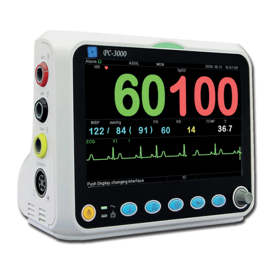
- Page 1 PROFESSIONAL MEDICAL PRODUCTS MULTI-PARAMETER PATIENT MONITOR User Manual 35134 0476 Gima S.p.A. Via Marconi, 1 - 20060 Gessate (MI) Italy gima@gimaitaly.com - export@gimaitaly.com www.gimaitaly.com Made in China...
- Page 2 Preface Manual Purpose The instructions for safe operation of product in keeping with its function and intended use are contained in this manual. In order to operate product properly, and to protect both the patient and operator from injury, compliance with this manual is first priority. Based on the maximum configuration, some contents of this manual may not apply to your product.
- Page 3 Terms used in this User Manual: "View": Main screen when there is no any pop-up window. "Long press": The operation pressing shortcut key for over 3 seconds. "SpO ": Oxygen saturation. Notes: This patient monitor can be customized with different functional modules, therefore, the monitor you purchased may not cover all operations described.
-
Page 4: Table Of Contents
Table of Contents Chapter 1 Safety ..............................1 1.1 Safety Information ............................1 1.1.1 Warnings ............................1 1.1.2 Cautions ............................2 1.1.3 Notes ..............................2 1.2 Equipment Symbols .............................4 1.2.1 Symbol/Icon on the Device.......................4 1.2.2 Icons List on the Screen ........................5 Chapter 2 The Basics ..............................7 2.1 Monitor Description ............................7 2.1.1 Product Name and Model ........................7 2.1.2 Intended Use ............................7... - Page 5 3.6 Data Uploading ............................20 Chapter 4 Screen Display ............................21 4.1 SpO2 Trend Data List Screen ........................21 4.1.1 Screen Description......................... 21 4.1.2 Operating Instructions ........................21 4.2 NIBP Data List Screen ..........................21 4.2.1 Screen Description......................... 21 4.2.2 Operating Instructions ........................22 4.3 Screen Display for Graphic Trend ......................
- Page 6 5.1 System Parameter Settings ........................35 5.2 Network Related Settings ......................... 36 5.3 ECG Related Settings ..........................37 5.4 Temperature Related Settings ........................38 5.5 NIBP Related Settings ..........................39 Related Settings ..........................40 5.6 SpO 5.7 Respiration Related Settings ........................40 Chapter 6 Alarms ..............................
- Page 7 7.6.1 Understand the ARR Type......................54 7.7 About S-T Segment Monitoring ........................ 55 7.8 Freezing Waveform ........................... 56 7.9 Factors Affecting ECG signal ........................56 Chapter 8 Monitoring Respiration (RESP) ......................57 8.1 Introduction .............................. 57 8.2 Safety Information ............................ 57 8.3 Understanding the RESP Display ......................
- Page 8 11.2 Safety Information ..........................69 11.3 Making a TEMP Measurement ....................... 69 11.4 Understanding the TEMP Display ......................70 11.5 Changing TEMP Settings ......................... 70 Chapter 12 Screen Display for Remote Observation ....................71 12.1 Default Remote Screen ........................... 71 12.2 NIBP Screen Display ..........................
- Page 9 17.8 Data Recording ............................90 17.9 Other Technical Specifications ........................ 90 17.10 Classification ............................90 17.11 Operating Environment ........................91 17.12 Storage ..............................91 17.13 Transportation ............................91 17.14 Packaging .............................. 92 Chapter 18 Troubleshooting ..........................93 18.1 No Display on the Screen ........................93 18.2 Excessive ECG Signal Interference or too Thick Baseline ................
-
Page 10: Chapter 1 Safety
Operator’s Manual for Patient Monitor Chapter 1 Safety 1.1 Safety Information The safety statements presented in this chapter refer to the basic safety information that the operator of the monitor shall pay attention to and abide by. There are additional safety statements in other chapters or sections, which may be the same as or similar to the followings, or specific to the operations. -
Page 11: Cautions
Operator’s Manual for Patient Monitor Do not silence the audible alarm if patient safety may be compromised. The monitor is prohibited from applying to those who have severe hemorrhagic tendency or who are with sickle cell disease for they may develop partial bleeding when this monitor is used to take the blood pressure measurement. - Page 12 Operator’s Manual for Patient Monitor ☞ After the life cycle of the monitor and its accessories has been met, disposal should be accomplished following national and/or local requirements. ☞ If the user requires more information such as circuit diagrams, parts list and product descriptions, for repairs carried out by qualified technical personnel, please contact us.
-
Page 13: Equipment Symbols
Operator’s Manual for Patient Monitor 1.2 Equipment Symbols 1.2.1 Symbol/Icon on the Device Item Symbol/Icon Description Power switch ECG lead key Alarm Silence key Freeze/ Unfreeze key Start/Cancel NIBP measurement Display view key AC power indicator Working power supply indicator Type CF applied parts with defibrillation-proof Warning --- refer to User Manual Type BF applied parts with defibrillation-proof... -
Page 14: Icons List On The Screen
Operator’s Manual for Patient Monitor The following definition of the WEEE label applies to EU member states only. This symbol indicates that this product should not be treated as household waste. Bu ensuring that this product is disposed of correctly, you will help prevent bringing potential negative consequences to the environment and human health. - Page 15 Operator’s Manual for Patient Monitor mm/s Unit of waveform sweeping speed NOTE: some symbols may not appear on your equipment...
-
Page 16: Chapter 2 The Basics
Operator’s Manual for Patient Monitor Chapter 2 The Basics 2.1 Monitor Description 2.1.1 Product Name and Model Product name: Patient Monitor Product Model: See Label in page I 2.1.2 Intended Use This Patient Monitor is a multi-functional instrument designed for monitoring the vital physiological signs of adult, pediatric and neonate patients. - Page 17 Operator’s Manual for Patient Monitor Seven traces of ECG waveforms on one screen view: displays 7 traces of ECG waveforms for different leads and monitoring parameters simultaneously on one screen. Five channels of real-time waveforms and two hours’ trends screen view: intuitive knowing the physiological status of patient.
-
Page 18: Main Unit
Operator’s Manual for Patient Monitor 2.2 Main Unit Front Panel Figure 2.1 Front Panel Note: The appearance described in this manual may be a little different with the monitor you purchased, for example, the operation keys may be located at the right side of the front panel. But the operating procedure is the same. - Page 19 Operator’s Manual for Patient Monitor according to the device setting, and enter into ST segment measurement screen for analysis (on Observing Screen). NIBP: Press to start or stop NIBP measurement. DISP: Click to shift the display modes or return to the Main Screen from other screens. Press it to shift between Main Screen and Display 2 Screen which can be set in System Menu screen.
- Page 20 Operator’s Manual for Patient Monitor Left and Right Panel Figure 2.2 the left panel Figure 2.3 the right panel Different ports are located in different positions of the monitor for operating convenience. The cable and transducer ports are an the left panel, shown in Figure 2.2. : SpO probe connector ...
- Page 21 Operator’s Manual for Patient Monitor Meanwhile, at the Patient Monitor side, the message "Data upload mode" will appear on its display screen. : Icon of DC power supply socket with polarity indication . Rear Panel Figure 2.4 Rear panel...
-
Page 22: Display Screen
Operator’s Manual for Patient Monitor 2.3 Display Screen Generally, when there is no pop-up window on the screen, the screen layout of the device includes information area, Waveform area and Parameter area, as shown in below Figure. Information area is on the top of the screen; Parameter area is on the right of the screen and Waveform area is on the left. -
Page 23: Information Area
Operator’s Manual for Patient Monitor 2.3.1 Information Area The Information Area will display the patient information (including gender, patient ID, patient type and name), physiological alarm sources, alarm sound status and current date. Alarm status Patient type ECG Filter type Network connection indicator Date and Time “Alarm... - Page 24 Operator’s Manual for Patient Monitor ECG panel: enter into ECG setting window NIBP panel: quick to enter into NIBP setting window Temperature panel: quick to enter into TEMP setting window panel: quick to enter into setting window Respiration panel: quick to enter into RESP setting window 2) Waveform area trace: The first trace is ECG waveform for lead II.
-
Page 25: Chapter 3 Operations
Operator’s Manual for Patient Monitor Chapter 3 Operations 3.1 Installation Devices connected to the equipment must meet the requirements of the applicable IEC standards. The system configuration must meet the requirements of the IEC 60601-1-1 medical electrical systems standard. Any personnel who connect devices to the equipment’s signal input/output port are responsible for providing evidence that the safety certification of the devices has been performed in accordance with IEC 60601-1-1. -
Page 26: Getting Started
Operator’s Manual for Patient Monitor The operating environment of the equipment must meet the requirements specified in this manual. Otherwise, unexpected consequences, e.g. damage to the equipment, could result. The environment where the equipment is used shall be reasonably free from noises, vibration, dust, corrosive, flammable and explosive substances. -
Page 27: Turning The Monitor On
Operator’s Manual for Patient Monitor Name Battery life Patient Monitor More than 120min NOTE: when the device is working, It takes at least 10 hours to charge battery from exhaust state to 90% charged. The provided battery of the monitor must be recharged after transportation or storage. So if the monitor is ... -
Page 28: Turning The Monitor Off
Operator’s Manual for Patient Monitor patient. Refer to the corresponding Section for details of how to perform the measurements you require. 3.3 Turning the Monitor Off To disconnect the monitor from the power, follow this procedure: 1. Confirm that patient monitoring is complete. 2. -
Page 29: Data Uploading
Operator’s Manual for Patient Monitor Step 1: rotate the knob to move the gray cursor to the corresponding item. Step 2: press the knob to enter the corresponding screen: SpO Data List Screen, NIBP Data List Screen, Graphic Trend Screen, Recall Screen, Arrhythmia Screen, System Setup Screen, Color Settings, File/Archive Management Screen, Tourniquet Function oxyCRG Screen, Event List Screen, MC Calculator Screen or Cuff ( ) Screen. -
Page 30: Chapter 4 Screen Display
Operator’s Manual for Patient Monitor Chapter 4 Screen Display 4.1 SpO2 Trend Data List Screen Figure 4.1 Trend Data Listing Screen 4.1.1 Screen Description When monitoring, the newest data will be displayed on the top of list including “Time, HR, RR, TEMP, SpO , PR”. -
Page 31: Operating Instructions
Operator’s Manual for Patient Monitor When monitoring, the newest data will be displayed on the top of list including “Time, NIBP, PR, HR, RR, TEMP”. The time shows the time when the NIBP measurement was taken. Up to 6 groups of NIBP data can be displayed on one screen. - Page 32 Operator’s Manual for Patient Monitor The Trend graph shows parameter value of the current time. For example, in the “5 sec” trend graph, the monitoring can record the current data with the interval of 5 seconds. Once the monitor is out of power, the data can be stored automatically and you can scan the history record when turning on the monitor next time.
-
Page 33: Operation Instructions
Operator’s Manual for Patient Monitor Figure 4.7 Trend graph Figure 4.8 PR Trend Graph Figure 4.9 Respiration Trend Graph 4.3.2 Operation Instructions Rotate the Navigation Knob to choose the parameter and press the knob to review the trend graph. Pressing “ ”... -
Page 34: Operation Instructions
Operator’s Manual for Patient Monitor Figure 4.10 Waveform Recall Screen It shows the monitoring can recall the history data continuously. If you change the patients’ ID or the monitor is out of power, the measuring data will not being a new single record, but connect to the last record you have measured. It is a continuous record. - Page 35 Operator’s Manual for Patient Monitor Figure 4.12 Recalled ECG Waveform Rotate the “Navigation Knob” to move forward or backward to review the ECG waveform. Press the “Navigation Knob” to exit the ECG waveform recall and return to the initial ECG waveform recall screen. During ECG waveform recall, the monitor not only displays the current recalled waveform, but also displays the setting of ECG lead, gain and filter type for the recalled waveform and timestamp.
-
Page 36: Screen Display For Arrhythmia Event List
Operator’s Manual for Patient Monitor 4.5 Screen Display for Arrhythmia Event List Figure 4.13 Arrhythmia Event List Screen 4.5.1 Operation Instructions The structure is similar to the recall screen. We will cover each function key below. Start: This button is used to start and end the system Arrhythmia detection. The default is OFF. When the Arrhythmia is not ON, the “Learn”... -
Page 37: Screen Display For System Setting
Operator’s Manual for Patient Monitor Exit: press this key to exit the Arrhythmia detection screen and return to the System Menu screen. During monitoring, if an ARR event is detected, the monitor will alarm. The ARR alarm is system default and does not need setup. -
Page 38: How To Change The Parameter Color
Operator’s Manual for Patient Monitor Figure 4.15 Display Color Settings 4.7.1 How to Change the Parameter Color Step 1: rotate the knob to move the gray cursor to the setting item and press the knob to confirm your selection. Step 2: rotate the knob to choose the color. Step 3: press the knob again to confirm the chosen color. -
Page 39: Oxycrg Screen
Operator’s Manual for Patient Monitor The patient ID is the unique identifier for the patient. When the patient ID changes, the system considers the patient has changed. Name: Enter the patient’s name. Bed: Enter the bed number. Sex: Choose between M or F for male and female. Age: Choose the age field and use the “Navigation Knob”... -
Page 40: Event List Screen
Operator’s Manual for Patient Monitor 4.10 Event List Screen Figure 4.18 Event List 4.10.1 Screen Description The Event List displays the time, event type, the value detected and high and low alarm limits. The time shows the time when the event occurred. Up to 5 groups of event data can be displayed on one screen. 4.10.2 Operating Instructions Up to 2000 groups of event data can be memorized. - Page 41 Operator’s Manual for Patient Monitor Medicine types which can be perform drug dosage calculation: AMINOPHYLLINE, DOBUTAMINE, DOPAMINE, EPINEPHRINE, HEPARIN, ISUPREL, LIDOCAINE, NIPRIDE, NITROGLYCERIN, and PITOCIN. Drug Dosage Calculation adopts the following formula: Medicine Consistency (MC) =Medicine Gross/ Cubage (Dose/minute)= (Dose/hour) /60 (Dose/Kg/m)= (Dose/m) /Weight (Dose/Kg/h)= (Dose/h) /Weight Transfusion Speed (TS) = (Dose/h) /MC...
- Page 42 Operator’s Manual for Patient Monitor Select Medicine Type: Move the cursor to “Medicine”, rotate Navigation knob to perform selection. Ten options: AMINOPHYLLINE, DOBUTAMINE, DOPAMINE, EPINEPHRINE, HEPARIN, ISUPREL, LIDOCAINE, NIPRIDE, NITROGLYCERIN, and PITOCIN. The default medicine is AMINOPHYLLINE. Weight: when entering into medicine calculating window, the operator should enter patient’s weight; the weight is used for MC calculation only;...
-
Page 43: Tourniquet Function
Operator’s Manual for Patient Monitor 4.12 Tourniquet Function Figure 4.21 Tourniquet “Pressure”: when you use Tourniquet function, you need to preset a cuff pressure for hemostasia. The pressure is adjustable, and its adjusting limit is different depending on patient type: for neonate: preset range: 70~100 mmHg, default value: “90”... -
Page 44: Chapter 5 Parameter Settings
Operator’s Manual for Patient Monitor Chapter 5 Parameter Settings Step 1: rotate the knob to move the gray cursor to the setting item and press the knob to confirm your selection. Step 2: rotate the knob to change the setting or modify the setting value. Step 3: press the knob again to change and repress it to save the setting. -
Page 45: Network Related Settings
Operator’s Manual for Patient Monitor LANG: The current language used, which can be selected by the user. There is no default for this setting. However, the setting can be saved. Fill: When the fill setting is ON, the plethysmogram and respiration waveform will be displayed with filled curves. ... -
Page 46: Ecg Related Settings
Operator’s Manual for Patient Monitor Local IP Address: the local IP address for this device working as a client. Server IP Address: the IP address of the remote server (work station) when connecting to a central monitoring system. Port: the remote port number to which the monitor will connect to the work station in the central monitoring ... -
Page 47: Temperature Related Settings
Operator’s Manual for Patient Monitor The factory default is MON. 1mV: Generating the 1mV calibrating signal. This signal is used to test the ECG function of the device. It is not used during normal operation. Factory default is OFF Notch: frequency filter. -
Page 48: Nibp Related Settings
Operator’s Manual for Patient Monitor Lo: Low alarm limit for temperature Unit: the temperature unit, and ℃ (Celsius) and ℉ (Fahrenheit) can be selected, the factory default is " ℃ ". Sensor: temperature sensor type, "KRK" and "YSI" can be selected. KRK and YSI temperature sensors are different ... -
Page 49: Spo Related Settings
Operator’s Manual for Patient Monitor SYS Hi/Lo: High and Low alarm limits for systolic pressure DIA Hi/Lo: High and Low alarm limits for diastolic pressure MAP Hi/Lo: High and Low alarm limits for MAP PR Hi/Lo: High and Low alarm limits for PR ... - Page 50 Operator’s Manual for Patient Monitor Figure 5.7 Respiration related settings Gain: Respiration amplification/gain, 4 options, x1/2, x1, x2, and x4. The default is x2 Speed: Respiration waveform sweeping speed, 2 options 6.25mm/s and 12.5 mm/s. The default is 12.5 mm/s ...
-
Page 51: Chapter 6 Alarms
Operator’s Manual for Patient Monitor Chapter 6 Alarms Alarms, triggered by a vital sign that appears abnormal or by technical problems of the monitor, are indicated to the user by visual and audible alarm indications. 6.1 Alarm Categories By nature, the monitor’s alarms can be classified into three categories: physiological alarms, technical alarms and prompt messages. -
Page 52: Alarm Indicators
Operator’s Manual for Patient Monitor Physiological alarm Alarm Alarm priority Alarm Event Source level Unable to detect HR, ECG Arrest, ECG Brady, ECG Tachy, VE RUN,SVE RUN, HR is too high, HR is too low, S-T is too high, S-T is too low, VE Run, ECG VPCEST Unable to detect SpO , SpO too high, SpO... -
Page 53: Alarm Lamp
Operator’s Manual for Patient Monitor 6.3.1 Alarm lamp Lamp color Alarm level Alarm event Red flashing High priority alarm ECG Brady, ECG Tachy, Low battery, Vital sign alarm Yellow flashing Medium priority alarm Lead off, Probe off, Sensor off, VE RonT,SVE RonT Yellow Low priority alarm Other Arrhythmia event... -
Page 54: Changing Alarm Volume
Operator’s Manual for Patient Monitor ③ " " means the alarm sound is paused. Text display area: when the alarm sound is paused, it displays counting-down time, otherwise, it displays the date. Move the cursor on this text display area can bring up the edit box of "Alarm volume"... - Page 55 Operator’s Manual for Patient Monitor Setting range Parameter High limit Low limit HR(bpm) (Low limit+1)~350 0~(High limit-1) S-T(mV) (Low limit+0.01)~2.50 -2.5~(High limit-0.01) (Low limit+1)~100 0~(High limit-1) (%) PR(bpm) (Low limit+1)~300 0~(High limit-1) RR(rpm) (Low limit+1)~150 0~(High limit-1) (Low limit+0.1)~60.0 0~(High limit-0.1) TEMP1(℃)...
-
Page 56: Factory Default Alarm Limit Setting Value
Operator’s Manual for Patient Monitor 6.4.2 Factory Default Alarm Limit Setting Value Type Adult Pediatric Neonate Parameter High limit 180 bpm 200 bpm 220 bpm Low limit 40 bpm 50 bpm 50 bpm High limit 30 rpm 30 rpm 100 rpm Low limit 8 rpm 8 rpm... - Page 57 Operator’s Manual for Patient Monitor 2. Confirm the alarming parameter or alarm category. 3. Identify the source of the alarm. 4. Take proper action to eliminate the alarm condition. 5. Make sure the alarm condition is corrected.
-
Page 58: Chapter 7 Ecg Monitoring
Operator’s Manual for Patient Monitor Chapter 7 ECG Monitoring 7.1 Introduction The electrocardiogram (ECG) is primarily a tool for evaluating the electrical events within the heart. The ECG signals can be detected by electrodes at the surface of the skin, this device connects ECG signals and represents them on the monitor as waveforms and numerical value such as heart rate. -
Page 59: Preparing To Monitor Ecg
Operator’s Manual for Patient Monitor Transient caused by cable circuitry blocks while monitoring may cause artifact on ECG signals yielding wrong heart rate reading and even triggering false alarm. If the electrodes and cable are located in proper places according to this manual’s instructions for using electrodes, the chance of this transient occurrence will be decreased. -
Page 60: Ecg Electrodes Placement
Operator’s Manual for Patient Monitor The symbol indicates that the cable and accessories are designed as the “CF” type level for protection against electric shocks and with defibrillation-proof capability. 7.3.2 ECG Electrodes Placement Electrode Placement The ECG leads and their corresponding locations are as follows: Electrode connection 1 Electrode connection 2 (IEC Standard) -
Page 61: Understanding The Ecg Display
Operator’s Manual for Patient Monitor Midway between V2 and V4 White/green Brown/green IC space on left midclavicular line White/brown Brown/blue (blue) White/black Brown/red Left anterior axillary line at the horizontal level of V4 White/purple Brown/purple Left midaxillary line at the horizontal level of V4 7.4 Understanding the ECG Display Your display may be configured to look slightly different. -
Page 62: Changing Ecg Settings
Operator’s Manual for Patient Monitor " ": the heart-beat symbol, blinks corresponding to the R wave of ECG waveform. The flashing speed is the same with the heart rate "180/50": high and low alarm limit setting for heart rate. ... -
Page 63: Understand The Arr Type
Operator’s Manual for Patient Monitor ☞ During Arrhythmia detection, incorrect detection might occur if the non-ECG waveforms (e.g. square or triangle waveform) appear. ☞ Before starting the 1mV calibration signal, please turn off the Arrhythmia detection. ☞ During Arrhythmia detection, the template learning is very important. The device requires a group of stable QRS complex waveforms to build up this template. -
Page 64: About S-T Segment Monitoring
Operator’s Manual for Patient Monitor VE TRIGEMINY Ventricular Trigeminy SVE TRIGEMINY Supra-ventricular Trigeminy VE INSERT Ventricular Insert SVE INSERT Supra-ventricular Insert VE RONT Ventricular RonT SVE RONT Supra-ventricular RonT 7.7 About S-T Segment Monitoring Alarm: to turn on or off over-limits alarms of HR and S-T, and set their high and low alarm limits. Setting range ... -
Page 65: Freezing Waveform
Operator’s Manual for Patient Monitor 7.8 Freezing Waveform When there are waveforms displayed on screen, press the Freeze key to enter into waveform freezing screen. During " and frozen time will be displayed on the upper right corner of the waveform area. freezing, the frozen symbol "... -
Page 66: Chapter 8 Monitoring Respiration (Resp)
Operator’s Manual for Patient Monitor Chapter 8 Monitoring Respiration (RESP) 8.1 Introduction Respiration is monitored by measuring the impedance across the thorax via electrodes places on chest. When the patient is breathing or ventilated, the volume of air changes in the lungs, resulting in impedance changes between the electrodes. -
Page 67: Changing Resp Settings
Operator’s Manual for Patient Monitor " ": Breath symbol. The blinking frequency is the same as the Respiration Rate. 8.4 Changing RESP Settings See Section 5.7 for details. -
Page 68: Chapter 9 Monitoring Nibp
Operator’s Manual for Patient Monitor Chapter 9 Monitoring NIBP 9.1 Introduction 9.1.1 The Oscillometric Blood Pressure Measurement This device applies the typical non-invasive blood pressure measurement with the oscillometric method. A cuff is used to occlude the artery by inflating it above the patient’s systolic pressure, the device measures the amplitude of pressure changes with pulsation in the cuff as the cuff pressure decreases. -
Page 69: Measurement Limitations
Operator’s Manual for Patient Monitor When an adult patient is monitored, the device may fail in giving the blood pressure measurement if the pediatric patient type is selected. Prior to use of the cuff, empty the cuff until there is no residual air inside it to ensure accurate measurement. ... -
Page 70: Setting Up The Nibp Measurement
Operator’s Manual for Patient Monitor 9.5 Setting Up the NIBP Measurement 9.5.1 Preparing to Measure NIBP 1. Power on the monitor. 2. Check the patient information area on the screen. Set a correct patient type, select a correct cuff size. 3. -
Page 71: Factors Affecting Nibp Measurement
Operator’s Manual for Patient Monitor blood pressure measurements immediately. 9.5.3 Factors Affecting NIBP Measurement Like common non-invasive blood pressure measurement, improper operation may cause inaccurate or blank result or misunderstanding of the measuring information when the oscillometric method is used to take the blood pressure measurement. -
Page 72: Changing Nibp Settings
Operator’s Manual for Patient Monitor NIBP label and unit Systolic pressure value Diastolic pressure value Mean arterial pressure NIBP measurement mode Pulse rate value "NIBP":the label of blood pressure. "129" is the systolic pressure value, "86" is the diastolic pressure value, and ... -
Page 73: Chapter 10 Monitoring Oxygen Saturation (Spo 2 )
Operator’s Manual for Patient Monitor Chapter 10 Monitoring Oxygen Saturation (SpO 10.1 Introduction The functional oxygen saturation (SpO ) - a percentage of the hemoglobin that can transport oxygen, is monitored by this device via a non-invasive optical technique. Based on the principle that oxygenated hemoglobin (HbO ) and deoxygenated hemoglobin (Hb) have different absorption character in the spectrum range from red to infrared light, the device measures the amount of oxygenated hemoglobin and pulse rate by measuring the absorption of selected... -
Page 74: Apply The Sensor
Operator’s Manual for Patient Monitor Do not apply tape to secure the sensor in place or to tape it shut; venous pulsation may lead to inaccurate oxygen saturation measurements. Vigorous movement of the patient, strong ambient light, or extreme electro-surgical interference may also ... -
Page 75: Using Probe And Sensor
Operator’s Manual for Patient Monitor 1.Select an appropriate sensor and probe according to the module type and patient category.. 2. Apply the sensor to the proper site of the patient. 3. Select an appropriate adapter cable according to the connector type and plug this cable into the SpO connector. - Page 76 Operator’s Manual for Patient Monitor (A) Hold the sensor with its opening towards the patient’s finger, the sensor should be oriented in such a way that the sensor side with a finger tip sign is positioned on the top. (B) Insert the patient’s finger into the sensor until the fingernail tip rests against the stop at the end of the sensor. Adjust the finger to be placed evenly on the middle base of the sensor.
-
Page 77: Understanding The Spo 2 And Pr Display
Operator’s Manual for Patient Monitor Foot wrap Ankle wrap 10.5 Understanding the SpO and PR Display Plethysmogram: "Pleth": label for abbreviation of plethysmogram. Panel: Label of pulse rate label Pulse rate value Pulse intensity bar graph value Label and value of High and low alarm perfusion index limit for SpO... -
Page 78: Chapter 11 Monitoring Temperature
Operator’s Manual for Patient Monitor Chapter 11 Monitoring Temperature 11.1 Introduction The body temperature is monitored by direct measuring mode with the temperature sensor of thermistor type. Very small amount of constant current is applied to the temperature sensor to avoid self-heating, the voltage across the thermistor is measured, and further converted to the temperature reading according to the temperature-resistance characteristic for a specific type of thermistor. -
Page 79: Understanding The Temp Display
Operator’s Manual for Patient Monitor Incompatible components can result in degraded performance. Operation Procedures for thermal temperature transducer: 1. Securely attach the transducer to the patient; 2. Connect the cable to TEMP probe connector marked "TEMP" in the panel. 3. -
Page 80: Chapter 12 Screen Display For Remote Observation
Operator’s Manual for Patient Monitor Chapter 12 Screen Display for Remote Observation 12.1 Default Remote Screen Press the DISP key to shift screen to Observing Screen when setting Disp2 as “Obsev” in System Setup screen, as shown in Figure 13.1. Figure 12.1 Screen display for remote observation Operation Instructions: ECG lead: press it to shift the ECG monitoring circulatory among Ⅰ, Ⅱ, and Ⅲ, aVR, aVL, aVF and V. -
Page 81: Nibp Screen Display
Operator’s Manual for Patient Monitor Navigation Knob: No action. When pressing the “Freeze” key, this key is used for S-T segment analysis. 12.2 NIBP Screen Display Figure 12.2 NIBP Screen display Press the DISP key to shift the Main Screen to NIBP screen , as shown in Figure, when setting Disp 2 as “NIBP” in “system menu→system setup→Disp2”. -
Page 82: Screen Display With Ecg Waveforms Only
Operator’s Manual for Patient Monitor 12.3 Screen Display with ECG Waveforms only Press the DISP key to shift screen to 7 ECG Waveform Screen when setting Disp2 as “7 ECG” in System Setup screen. In this screen, the operator can view 7 traces of ECG waveforms simultaneously for lead I, II, III, AVR, AVL, AVF and V, as shown in Figure 2.9. - Page 83 Operator’s Manual for Patient Monitor Navigation Knob: rotate the knob to adjust the gain for all 7 trace of ECG waveforms. The ECG gain includes 6 options: “Auto”, “X1/4” “X1/2”, “X1”, “X2”, “X4”. Notes: 1. For the monitor without ECG function, the display view of 7 traces of ECG waveforms will not be available. 2.
-
Page 84: Five Channels Real-Time Waveforms And Trends On The Same Screen
Operator’s Manual for Patient Monitor 12.4 Five Channels Real-time Waveforms and Trends on the Same Screen Note: this display view is not available for the monitor without ECG function. When the Disp2 option is “Trend” on System Menu screen, press the DISP key on the Main Screen, the system will enter the trend screen, as shown in Figure 12.4. -
Page 85: Parameter Screen
Operator’s Manual for Patient Monitor system setting. Double press this key within 2 seconds to lock or unlock the operation of all other buttons (except power switch) on the front panel. NIBP: press it to start or stop NIBP measure. DISP: press it to shift the display to the Main Screen. - Page 86 Operator’s Manual for Patient Monitor DISP: press it to shift the display to the Initial Screen. Navigation Knob: no action.
-
Page 87: Chapter 13 Battery
Operator’s Manual for Patient Monitor Chapter 13 Battery 13.1 Overview The monitor has built-in chargeable battery, when the monitor is disconnected from the external AC power supply, then it turns to be powered by built-in battery. When the monitor is supplied by external AC power, then the battery will be charged. -
Page 88: Battery Recycling
Operator’s Manual for Patient Monitor Warning: 1. To avoid battery damage always remove battery(s) before shipping or storage. 2. It is recommend to use the battery specified by the manufacturer. 3. Life expectancy of a battery depends on how frequently and how long it is used. For a properly maintained and stored lead-acid or lithium battery, its life expectancy is about 2 or 3 years respectively. -
Page 89: Chapter 14 Cleaning And Disinfection
Operator’s Manual for Patient Monitor Chapter 14 Cleaning and Disinfection 14.1 Cleaning the Device and Accessories Your device should be cleaned on a regular basis. If there is heavy pollution or lots of dust and sand in your place, the device should be cleaned more frequently. -
Page 90: Disinfecting The Device And Accessories
Operator’s Manual for Patient Monitor use an outlet with poor condition. If possible, use power supply system with regulator. It must be used in a clean environment protected against shock. Keep it away from corrosive substances, explosive substances, high temperature and dampness. If it is installed in a cabinet, make sure the installation allows for good ventilation, and easy maintenance, ... -
Page 91: Chapter 15 Maintenance
Operator’s Manual for Patient Monitor Chapter 15 Maintenance In case of trouble of this machine in the service, follow the instructions below to eliminate the problem first. If the attempt fails, refer to the dealer in your local area or the manufacturer. Refer to the detailed provisions in contract for the warranty period of the main unit and the accessories of this monitor. -
Page 92: Ecg Verification
Operator’s Manual for Patient Monitor The SpO simulator can not be used to verify the SpO measuring accuracy, which should be supported by the clinical study conducted by inducing hypoxia on healthy, non-smoking, light-to-dark-skinned subjects in an independent research laboratory. However it is necessary for the user to use SpO simulator for routine verification of precision. - Page 93 Operator’s Manual for Patient Monitor Mercury blood pressure meter NIBP cuff with dual air tube Air tube Air tube Air tube Air tube Air vent Increase the pressure manually Manual valve Module testing through the inflatable balloon NIBP software Inflation balloon module This belongs to the monitor Mode 1: Automatic inflation for the pressure accuracy verification...
- Page 94 Operator’s Manual for Patient Monitor Adult 300mmHg Pediatric 240mmHg Neonate 140mmHg Table B After the verification, do press the button again to return to normal working mode, then continue other operation, or the NIBP key will be invalid. Pressure accuracy verification must be operated by technician or equipment manager. Doctor or nurse is not allowed to do the verification, it is very dangerous especially when the pressure cuff is still on patients.
-
Page 95: Accessories
Operator’s Manual for Patient Monitor 16 Accessories Check the accessories and their package for any signs of damage. Do not use them if any damage is detected. Item Description Material No. Remark PC-3000 Main set Handle Subassembly Adult SpO probe 15044074 NIBP cuff... -
Page 96: Technical Specifications
Operator’s Manual for Patient Monitor 17 Technical Specifications 17.1 ECG 1. Input dynamic range: ±(0.5mVp ~ 5mVp) 2. Heart rate display range: 15 bpm ~ 350 bpm ( for Adult and Pediatric) 3. Heart rate display accuracy: ±1% or ±2bpm, whichever is greater. 4. -
Page 97: Resp
Operator’s Manual for Patient Monitor 17.2 RESP 1. RESP rate measuring range: 0rpm~120rpm 2. RESP rate accuracy: ±5% or ±2 rpm, whichever is greater 3. RESP rate alarm limit setting range: High: 1rpm~150rpm; Low: 0rpm~149rpm. 4. Alarm tolerance: ±1rpm 17.3 TEMP 1. -
Page 98: Spo
Operator’s Manual for Patient Monitor 10. NIBP accuracy: Maximum mean difference: ±5 mmHg Maximum Standard deviation: 8 mmHg 11. Measurement mode: Manual, Auto, STAT 12. NIBP Alarm setting range: see Section Alarms 17.5 SpO 1. Transducer: dual-wavelength LED Wavelength: Red light: 660 nm, Infrared light: 905 nm Maximal optical output power: less than 2mW maximum average 2. -
Page 99: S-T Segment
Operator’s Manual for Patient Monitor 17.7 S-T Segment 1. Measuring range: -2.0mV~+2.0mV 2. Tolerance: -0.8mV~+0.8mV ±0.02mV or ±10% (which is greater) 17.8 Data Recording 1. Sensitivity selection tolerance: ±5% 2. Recording speed: 25mm/s 3. Recording speed accuracy: ±10% 4. Hysteresis: ≤0.5mm 5. -
Page 100: Operating Environment
Operator’s Manual for Patient Monitor 17.11 Operating Environment 1. Ambient temperature range: 5°C~40°C Relative humidity: 15%~85%, non-condensing Atmospheric pressure: 70kPa ~106.0kPa Power Voltage: (100-240)VAC Power frequency: 50Hz/60Hz 2. This equipment should be situated in a place protected against direct sunlight, so as to prevent overheating inside the equipment. -
Page 101: Packaging
Operator’s Manual for Patient Monitor relative humidity: 10%~95% atmospheric pressure: 53kPa~106kPa 17.14 Packaging The product is packed in high quality corrugated cartons with foam inside to protect the apparatus against damage in the handling process. Gross weight: Details see the indication on the outer package Dimension: Details see the indication on the outer package... -
Page 102: Chapter 18 Troubleshooting
Operator’s Manual for Patient Monitor Chapter 18 Troubleshooting Note: In case of trouble of this machine in service, follow the instructions below to eliminate the problem first. If the attempt fails, contact the dealer in your local area or the manufacturer. Do NOT open the monitor cabinet without permission ... -
Page 103: Power Supply Failure
Operator’s Manual for Patient Monitor Symptoms Possible cause Correction action The alarm LED does not light Main board is defective Replace the main board No alarm sound is issued Audible alarm is disabled ” Check if the “ is displayed, if yes, the audible alarm is disabled. -
Page 104: A Alarm Information
Operator’s Manual for Patient Monitor A Alarm Information Alarm Information Descriptions Over HR limit Over RR limit Over TEMP limit Over SpO limit Over PR limit Over NIBP SYS limit The related parameter value exceeds the preset high/low alarm Over NIBP DIA limit limits. -
Page 105: B Status/Error During Nibp Monitoring
Operator’s Manual for Patient Monitor B Status/Error during NIBP Monitoring “Cuff error” —cuff is not wrapped correctly, or is not connected “Air leak” —Air moving part, tube or the cuff leak air. “Pressure error” —Unstable cuff pressure or tangled cuff tubing “Signal weak”... -
Page 106: C Emc Compliance
Operator’s Manual for Patient Monitor C EMC Compliance Essential Performance The monitor has the following essential performance in an environment of electromagnetic environment specified below: Operating mode, accuracy, function, alarm Warnings Use of the monitor adjacent to or stacked with other equipment should be avoided because it could result in improper operation. - Page 107 Operator’s Manual for Patient Monitor Electromagnetic compatibility Levels of compliance with the EN 60601-1-2:2015 standard - ESD immunity 15kV for air discharge 8 kV for contact discharge (EN 61000-4-2) - 2kV/100kHz burst immunity (EN 61000-4-4) power supply/1kV signals - Surge immunity (EN 61000-4-5): 1kV common/2kV differential - Magnetic field (EN 61000-4-8): 30A/m - Dip Immunity: 0% 0.5 cycles;...
- Page 108 Disposal: The product must not be disposed of along with other domestic waste. The users must dispose of this equipment by bringing it to a specific recycling point for electric and electronic equip- ment. GIMA WARRANTY TERMS The Gima 12-month standard B2B warranty applies.
Need help?
Do you have a question about the 35134 and is the answer not in the manual?
Questions and answers