Table of Contents
Advertisement
Quick Links
PROFESSIONAL MEDICAL PRODUCTS
MULTI-PARAMETER PATIENT MONITOR
User Manual
ATTENTION: The operators must carefully read and completely
understand the present manual before using the product.
35134
Gima S.p.A.
Via Marconi, 1
20060 Gessate (MI) - Italy
Made in China
Gima S.p.A.
Via Marconi, 1 - 20060 Gessate (MI) Italy
gima@gimaitaly.com - export@gimaitaly.com
www.gimaitaly.com
0476
Advertisement
Table of Contents

Subscribe to Our Youtube Channel
Related Manuals for Gima 35134


Summary of Contents for Gima 35134
- Page 1 Gima S.p.A. Via Marconi, 1 - 20060 Gessate (MI) Italy gima@gimaitaly.com - export@gimaitaly.com www.gimaitaly.com PROFESSIONAL MEDICAL PRODUCTS MULTI-PARAMETER PATIENT MONITOR User Manual ATTENTION: The operators must carefully read and completely understand the present manual before using the product. 35134 0476 Gima S.p.A.
- Page 2 This Manual is written and compiled in accordance with standards and requirements for electromedical de- vices. The Manual is written for the current Patient Monitor. The Manual describes, in accordance with the Patient Monitor’s features and requirements, main structure, functions, specifications, correct methods for transportation, installation, usage, repair, maintenance and stor- age, etc.
- Page 3 Do not immerse the monitor or its accessories in liquid to clean. Do not use accessories other than those provided/recommended by the. Each time the monitor is used, check the alarm limits to ensure that they are appropriate for the patient being monitored.
-
Page 4: Table Of Contents
INDEX PART I Chapter 1 Overview ............................7 1.1 Product Name ......................... 7 1.2 Applications and Scope ......................7 1.3 Operating Environment ......................7 1.4 Impact on Environment and Resources .................. 7 1.5 Safety ............................7 Chapter 2 Working Theories ........................8 2.1 Overall Structure ........................ - Page 5 7.6 Introduction to Capnograph Measurement ................34 7.6.1 CO 2 Measuring Principle ..................... 34 7.6.2 Mainstream vs. Sidestream Sampling ................. 34 Chapter 8 Troubleshooting ........................35 8.1 No Display on the Screen ..................... 35 8.2 Excessive ECG Signal Interference or too Thick Baseline............ 35 8.3 No Blood Pressure and Pulse Oxygen Measures ..............
- Page 6 3.5 Screen Display for Waveform Recall ..................60 3.5.1 Operation Instructions ....................60 3.6 Screen Display for Arrhythmia Event List ................61 3.6.1 Operation Instructions ....................61 3.7 Screen Display for System Setting ..................62 3.7.1 How to Select the System Setup Item ................. 62 3.7.2 Parameter Settings ......................
-
Page 7: Chapter 1 Overview
PART I Chapter 1 OVERVIEW 1.1 Product Name Name: MULTI-PARAMETER PATIENT MONITOR 1.2 Applications and Scope This Patient Monitor is a multi-functional instrument designed for monitoring the vital physiological signs of adult and pediatric patients. With the functions of real-time recording and displaying parameters, such as ECG, heart rate, non-invasive blood pressure, functional oxygen saturation, end-tidal CO concentration, respiration rate, body temperature, and so on, it allows comprehensive analysis of patient’s physiological conditions. -
Page 8: Chapter 2 Working Theories
Chapter 2 WORKING THEORIES 2.1 Overall Structure The overall structure of the monitor is shown as Figure 2.1 Figure 2.1 2.2 Composition 1. The monitor consists of the main units and the corresponding functional components (ECG cables/lead wires, non-invasive blood pressure cuff, SpO probe, temperature transducer, accessories for invasive blood pressure and CO monitoring). -
Page 9: Chapter 3 Installation And Connection
5. The mother board is the main controlling unit, which also connects to the interface board and key board. The interface board inter-connects the functional modules with the mother board. Chapter 3 INSTALLATION AND CONNECTION 3.1 Installation 3.1.1 Opening the Box and Check 1. -
Page 10: Starting The Monitor
3.1.3 Starting the Monitor The system performs self-test and enters initial display after switch on the monitor, and the alarm rings to in- form that the user can begin operating it. • Check all the applicable functions to make sure that the monitor works normally. •... - Page 11 It might not display ECG waveform when using ECG cable with 3 lead wires while the setting of “Ca- ble” is set as “5” in the ECG parameter setup menu. The ECG cable with 5 leads wires should be used to measure ECG signal at this situation.
-
Page 12: Cuff Connection For Blood Pressure Measurement
ECG cable and/or lead wires may be damaged while using defibrillator. If the cable and/or lead wires are used again, please do the functional check firstly. When the monitor is inoperable due to overload of ECG or saturation of any part of the amplifier, it will prompt “Lead off”... - Page 13 Mercury blood pressure meter NIBP cuff with dual air tube Air tube Air tube Air tube Air tube Air vent Manual valve Module NIBP Increase the pressure testing Inflation module manually through the software balloon inflatable balloon Inside the monitor Figure 3.7 Connection of Pressure Accuracy Verification Fixture Mode 1: Automatic inflation for the pressure accuracy verification At this mode, the monitor can activate the inflation, so the pressure will increase automatically until it exceeds...
-
Page 14: Spo 2 Probe Connection
(e.g. all models of Pa- tient Monitors made by Gima) or pulse oximeters (e.g. 34342 Handheld Pulse Oximeter made by Gima). The sensor is intended to be used for continuous, non-invasive functional arterial oxygen saturation (SpO and pulse rate monitoring for adult patients weighing greater than 40kg or pediatric patients weighing between 10~40kg. - Page 15 Operation procedure: 1. Connect the SpO probe to the connector marked with “SpO ” icon on the signal input panel. When un- plugging the probe, be sure to hold the head of the connector and pull it out. 2. Insert one finger (index finger is preferred, but middle or ring finger with proper nail length is possible as well) into the probe according to the finger mark on the probe, shown as below.
- Page 16 Probe Patient Category Adult SpO Finger Clip Sensor (reusable) Adult Adult SpO Finger Rubber Sensor (reusable) Pediatric SpO Finger clip Sensor (reusable) Pediatric Y-type sensor with wrapper (reusable) Neonate 3. If the neonate SpO sensor is used, please follow figure to connect. Sensor adapter: wrapper Y type sensor Figure 3.8C Neonate SpO...
-
Page 17: Co 2 Sensor Connection
The fingernail should be of normal length. The SpO sensor cannot be immerged into water, liquor or cleanser completely, because the sensor has no capability to resist the harmful ingress water. Carefully route cables to reduce the possibility of patient entanglement or strangulation. Do not use the sensor or other oximetry sensors during MRI scanning. - Page 18 Extending airway tube for connecting to sampling tube (Single patient use) Wye Connector OPTIONAL SAMPLING CANNULA KITS 1) T connector sampling cannula kits On-air Connector Adapter 2) Nasal Sidestream Cannula Kits 3) Oral Sidestream Cannula Kits...
- Page 19 3.2.4.2 Mainstream CO Sensor Connection Sensor cable Adapter sensor Demonstration for Mainstream CO Sensor Connection 1. Take out the CO Sensor and insert the CO Sensor Cable into the connector labeled “CO ” on the con- nector panel of the monitor; 2.
-
Page 20: Temp Probe Connection
use the sidestream on-airway adapters and sidestream sampling kits if they appear to be damaged or bro- ken. If the CO waveform (Capnogram) appears abnormal, inspect the CO airway adapters and replace if need- Periodically check the CO 2 /Flow sensor and tu bing fo r excessive moisture or secretion buildup. Do not use them if there is excessive moisture or exterior condensation. -
Page 21: Loading Printing Paper
3.2.6 Loading Printing Paper This description is for loading paper for the built-in printer. Operation procedures: 1. Press both “OPEN” notches with force on printer shield with two thumbs to open it. 2. Move the tab of rubber roller lock at the left 90°upwards to unlock it. 3. -
Page 22: Chapter 4 Alarm
Loading printing paper: Step 1: press and hold down the cartridge button to open the paper cartridge; Step 2: Install the paper to the printer properly, pull the paper out of the printer for 2 cm, as shown in figure 3.12. -
Page 23: Alarm Modes
Related to 3 levels alarm modes, medical and nursing staff should have different response to deal with poten- tial dangerous, the detailed demands as follows:: 1. High priority alarm: medical and nursing staff should response immediately. 2. Medium priority alarm: medical and nursing staff should response quickly. 3. -
Page 24: Chapter 5 Technical Specifications
Audible Alarm Indications The audible alarm has different tone pitch and on-off beep patterns for each priority category. These are sum- marized in the Table below. High priority: A chain of 10 beeps with pause intervals in such way: x, x, 2x+td, x, 1s, x, x, 2x+td, x, 1s, where x (pulse interval)=100ms, td (beep duration)=160ms, 1s=1 second, the beep tone is 400Hz, the pause peri- od between every beeping chain is 5 seconds. -
Page 25: Resp Monitoring
Additional declarations to conform the particular standard of IEC 60601-2-27 “Medical electrical equipment – Part 2-27: Particular requirements for the safety, including essential performance, of electrocardiographic monitoring equipment” Direct current for respiration, leads-off Applied current less than 0.1 microamperes. sensing, and active noise suppression Response to irregular rhythm A1 Ventricular bigeminy-80BPM A2 Slow alternating ventricular bigeminy-60BPM... -
Page 26: Spo 2 Monitoring
5.5 SpO Monitoring 1. Transducer: dual-wavelength LED Wavelength: Red light: 663 nm, Infrared light: 890 nm. Maximal optical output power: less than 2mW maximum average 2. SpO measuring range: 35%~100% 3. SpO measuring accuracy: not greater than 3% for SpO range from 70% to 100% *NOTE: accuracy defined as root-mean-square value of deviation according to ISO 9919 4. -
Page 27: Guidance And Manufacturer's Declaration Electromagnetic Compatibility
5.11 Guidance and manufacturer’s declaration Electromagnetic compatibility Table 1 Guidance and manufacturer’s declaration-electromagnetic emission- for all EQUIPMENT AND SYSTEMS Patient Monitor is intended for use in the electromagnetic environment specified below. The customer or the user of the equipment or system should assure that it is used in such an environment. Emissions test Compliance Electromagnetic environment-guidance... - Page 28 Table 3 Guidance and manufacturer’s declaration – electromagnetic immunity-for EQUIPMENT and SYSTEM that are not LIFE-SUPPORTING Patient Monitor is intended for use in the electromagnetic environment specified below. The customer or the user of Patient Monitor should assure that it is used in such an electromagnetic environment.. IMMUNITY test IEC 60601 Compliance...
-
Page 29: Chapter 6 Packaging And Accessories
Table 4 Recommended separation distances between portable and mobile RF communications equipment and The equipment or system- for EQUIPMENT and SYSTEM that are not LIFE-SUPPORTING Patient Monitor is intended for use in an electromagnetic environment in which radiated RF disturbances are controlled. -
Page 30: Chapter 7 Working Principles
For Mainstream For Sidestream Mainstream sensor ( CAPNOSTAT 5 ) One set Sidestream Sensor (LoFlo C5) One set Airway adapter One piece Sampling Line Kit One set NOTE: The accessories are subject to change. Detailed items and quantity see the Packing List. Chapter 7 WORKING PRINCIPLES 7.1 Introduction to ECG Measurement... -
Page 31: Introduction To Blood Pressure Measurement
• Electrodes are not placed properly; • Use expired electrode or use disposable electrode repeatedly; • The skin placed electrode is unclean or poor contract caused by scurf and hair; • Electrode long-time used. 7.2 Introduction to Blood Pressure Measurement 7.2.1 Blood Pressure Measuring Principle Blood pressure may be measured in an invasive way (whereby the sensor will be inserted into blood vessel directly) or a non-invasive way. -
Page 32: Factors Affecting Nibp Measuring
But, it doesn’t mean the advantages or disadvantages between the oscillating method and the Korotkoff Sound Method. Comparison with the results taken by more accurate method, let’s say comparison of the invasive pressure result with the output value by the blood pressure measuring simulator, will show which method has more accurate results. -
Page 33: Introduction To Oxygen Saturation Measurement
It is normal in the scientific experiments. It may be caused by an apparent reason, or by an unknown factor in some cases. Such individual doubtful experimental data may be identified and eliminated using the special statistical technique. It is not a part of this manual. The practitioner may eliminate the apparently unreasonable data according to the experience. -
Page 34: Introduction To Respiration Measurement
7.4 Introduction to Respiration Measurement 7.4.1 Respiration Measuring Principle The air will be filled into alveolus or be expelled during respiration, and the chest’s volume changes with this process. Because the conductivity of air is lower than body tissues, the chest’s impedance will be changed by the inflation. -
Page 35: Chapter 8 Troubleshooting
Chapter 8 TROUBLESHOOTING NOTE: In case of trouble of this machine in service, follow the instructions below to eliminate the prob- lem first. If the attempt fails, contact the dealer in your local area or the manufacturer.. Do NOT open the monitor cabinet without permission 8.1 No Display on the Screen Shut down the machine and unplug the power cable. -
Page 36: Routine Maintenance
9.1.2 Routine Maintenance At each routinely maintenance or the yearly maintenance, the monitor can be thoroughly inspected by qualified personnel, including performance and safety examinations. This monitor is designed with life cycle of 5 years. It is strongly recommended to use the product which is still within its life cycle, or it may cause inaccurate measurement. -
Page 37: Cleaning And Disinfection Of Accessories
clean wipe or simply air-dry. • This monitor can be disinfected, please clean the monitor firstly. Do not let the liquid cleanser flow into the connector jack of the monitor to avoid damage. Clean the exterior of the connector only. ... -
Page 38: Chapter 10 Appendix
Chapter 10 APPENDIX 10.1 Alarm Information Alarm Information Descriptions Over HR limit Over RR limit Over TEMP limit The related parameter value exceeds the preset high/low alarm Over SpO limit limits. Over PR limit Over NIBP SYS limit Over NIBP DIA limit Over NIBP PR limit ECG cable and leads are connected to monitor and patient well, Unable to detect HR... -
Page 39: Default Alarming Values And Setup Range
10.2 Default Alarming Values and Setup Range The default alarming value Mode Adult pediatric Neonate Parameter High limit 180 bpm 200 bpm 220 bpm Heart Rate Low limit 40 bpm 50 bpm 50 bpm High limit 40 rpm 50 rpm 60 rpm Respiration Low limit... - Page 40 The high and low limits setting range Mode Adult Pediatric Neonate Parameter High limit 1~300 bpm 1~350 bpm 1~350 bpm Heart Rate Low limit 0~299 bpm 0~349 bpm 0~349 bpm High limit 1~120 rpm 1~150 rpm 1~150 rpm Respiration Low limit 0~119 rpm 0~149 rpm 0~149 rpm...
-
Page 41: Status/Error During Nibp Monitoring
10.3 Status/Error during NIBP Monitoring “Cuff error” Cuff is not wrapped correctly, or is not connected “Air leak” Air moving part, tube or the cuff leak air. “Pressure error” Unstable cuff pressure or tangled cuff tubing “Signal weak” Very weak signal because of the cuff, or the patient has very weak pulse “Over extent”... -
Page 42: Status/Error During Co 2 Monitoring
10.4 Status/Error during CO Monitoring Suggested Message/Response Description “Sensor Over Temp” Make sure sensor is not exposed to extreme The sensor temperature is greater than 40 °C. heat (heat lamp, etc.). If error persists, return sensor to factory for servicing. “Sensor Faulty”... -
Page 43: Typical Pressures And Co 2 Readings At Altitudes
10.5 Typical Pressures and CO Readings at Altitudes Altitude Barometric Pressure EtCO Reading (mmHg) (mmHg) 38,0 70 m 37,7 100 m 37,5 200 m 37,1 1500 m 32,0 3000 m 26,8 5000 m 21,0 10.6 Accessories List Part Name Remark ECG cable ECG electrode Adult SpO... -
Page 44: Chapter 1 Overview
PART II Chapter 1 OVERVIEW 1.1 Features This patient monitor can be used for monitoring multiple physiological parameters, such as ECG, non-invasive blood pressure (NIBP), oxygen saturation (SpO ), respiration rate (RR), pulse rate (PR), and body temperature. NOTE: If CO module is added, the monitoring will not have these two functions: central networking and body temperature (temperature connector doesn't exist) •... -
Page 45: Introduction To Panels
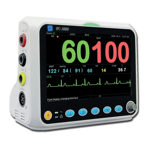
1.2 Introduction to Panels 1.2.1 Front Panel Figure 1.1 Front Panel NOTE: The appearance described in this manual may be a little different with the monitor you pur- chased, for example, the operation keys may be located at the right side of the front panel. But the operating procedure is the same. -
Page 46: Left And Right Panel
Freeze: Press the key to freeze/unfreeze ECG waveform or the waveforms of ECG, SpO and RESP according to the device setting, and enter into ST segment measurement screen for analysis (on Observing Screen). NIBP: Press it to start or stop NIBP measurement. ... -
Page 47: Rear Panel
Serial communication port which is used to network with central monitoring system (optional). USB port (reserved for future use); 4. : Icon of DC power supply socket with polarity indication . 1.2.3 Rear Panel Figure 1.4 Rear panel — battery lid. Remove the battery lid to install or change the rechargeable battery. Battery specifications: Li-ion 14.8V/2200mAh rechargeable battery pack. -
Page 48: Screen Description
the knob again and the gray cursor becomes highlighted. Rotate the knob left or right to increase or decrease the year value. Step 3: When the Year is set, press the knob to move the gray cursor to the Month of the date. Step 4: Repeat Step 2 and Step3 to adjust the Year, Month, Date, Hour and Minute. - Page 49 Waveform area • 1 trace: The first trace is ECG waveform for lead II. The left side of the ECG waveform shows the scale bar looking like “I”, which indicates the ECG scale. This scale bar will change its height according to the ECG gain setting.
- Page 50 Mark and unit of temperature Temperature value Temperature sensor type Figure 2.5 TEMP data area • “TEMP”: Temperature label. The value below “36. 7” is the temperature value. • “°C”: Body temperature unit. °C is Celsius, and °F is Fahrenheit. •...
-
Page 51: Screen Display For Remote Observation
2.3 Screen Display for Remote Observation 2.3.1 Screen Description Press the DISP key to shift screen to Observing Screen when setting Disp2 as “Obsev” in System Setup screen, as shown in Figure 2.7. Figure 2.7 Screen display for remote observation Operation Instructions: ECG lead: press it to shift the ECG monitoring circulatory among I, II, and III, AVR, AVL, AVF and V. -
Page 52: Screen Display With Ecg Waveforms Only
Press the DISP key to shift the Main Screen to NIBP screen , as shown in Figure, when setting Disp 2 as “NIBP” in “system menu system setup Disp2”. In NIBP screen, PR from SpO is shown prior to PR from NIBP Operation Instructions: EGG lead: No action. -
Page 53: Five Channels Real-Time Waveforms And Trends On The Same Screen
2.3.4 Five Channels Real-time Waveforms and Trends on the Same Screen When the Disp2 option is “Trend” on System Menu screen, press the DISP key on the Main Screen, the system will enter the trend screen, as shown in Figure 2.10. Five channel real-time waveforms and trend graph can be viewed on this screen. -
Page 54: Parameter Screen
Navigation Knob: no action. NOTE: when "3" lead wires are chosen in "Cable" setting of ECG Setup, then the display view of 2 hours trends screen will not be available. 2.3.5 Parameter Screen Press the DISP key to shift screen to Parameter Screen when setting Disp2 as “Parameter” in System Setup screen, as shown in Figure 2.11. -
Page 55: Ecg Waveform Freezing And S-T Segment Measurement
2.4 ECG Waveform Freezing and S-T Segment Measurement During the process of monitoring, the ECG waveform can be frozen to perform detailed analysis in the observ- ing screen, as shown in Figure 2.12. Figure 2.12 Frozen and S-T Analysis Screen 2.4.1 Screen Description The manual S-T segment measurement can be done at the frozen screen display. -
Page 56: Chapter 3 Screen Display For System Menu
NOTE: The S-T segment starts from the end point of S wave, and ends at the start point of T wave, the st point to be measured is a point within the S-T segment. Operation Instructions: ECG lead: press it to shift the ECG monitoring circulatory among I, II, and III, AVR, AVL, AVF and V. Alarm silence: press it to enable or disable the alarm silence function. -
Page 57: Screen Description
3.2.1 Screen Description When monitoring, the newest data will be displayed on the top of list including “Time, HR, RR, TEMP, SpO PR”. The time shows the time when the SpO measurement was taken. Up to 6 groups of SpO data can be displayed on one screen. -
Page 58: How To View The Graphic Trend
3.4.1 How to View the Graphic Trend Figure 3.4 is the HR trend graph. There are 3 options on the right of the graph, as described below. “HR” indicates the current trend graph is HR trend graph. If you want to enter other trend graphs, the proce- dures are: move cursor to “HR”... -
Page 59: Operation Instructions
Figure 3.7 ETCO Graphic Trend Figure 3.8 SpO Trend graph Figure 3.9 PR Trend Graph Figure 3.10 Respiration Trend Graph 3.4.2 Operation Instructions Rotate the Navigation Knob to choose the parameter and press the knob to review the trend graph. ... -
Page 60: Screen Display For Waveform Recall
3.5 Screen Display for Waveform Recall Figure 3.11 Waveform Recall Screen It shows the monitoring can recall the history data continuously. If you change the patients’ ID or the monitor is out of power, the measuring data will not being a new single record, but connect to the last record you have measured. -
Page 61: Screen Display For Arrhythmia Event List
HIST: Press the key to shift between the History key and Current key. Press HIST and the recall list on the left displays the history data list. Press the Current, the recall list on the left side displays the current one. When entering the recall screen display, the monitor defaults the current one. -
Page 62: Screen Display For System Setting
3.7 Screen Display for System Setting Figure 3.15 System Setup 3.7.1 How to Select the System Setup Item Step 1: rotate the knob to move the gray cursor to the corresponding item. Step 2: press the knob to enter the corresponding setting screen: System Setup, Printer Setup, ECG Setup, TEMP setup, CO Setup, NIBP Setup, SpO Setup, RESP Setup or resuming Default setting. - Page 63 • Frze: Pressed the key to freeze the selected waveforms. The options are “All” and “ECG”. When "ECG" is selected, the monitor only freezes the ECG waveform. When “All” is selected, the monitor freezes all the waveforms including ECG, plethysmogram, and respiration waveform. The factory default is “ECG”. •...
- Page 64 Figure 3.17 ECG related settings • Lead: Can be chosen among Lead I, II, III, AVR, AVL, AVF, and V (V1-V6). The default is I. • Gain: The ECG gain, 6 options x1/4, x1/2, x1, x2, x4 and Auto. Auto is for automatic gain control. The fac- tory default is x1.
- Page 65 • TEMP Hi: High alarm limit for temperature Lo: Low alarm limit for temperature • Unit: : the temperature unit, and °C (Celsius) and °F (Fahrenheit) can be selected, the factory default is "°C". • Sensor: temperature sensor type, "KRK" and "YSI" can be selected. KRK and YSI temperature sensors are different type of thermistors with different R-T characteristic.
-
Page 66: Display Color Settings
RELATED SETTINGS Figure 3.21 SpO related settings • SpO Hi/Lo: High and Low alarm limits for SpO • Pulse Hi/Lo: High and Low alarm limits for pulse rate. • Response speed: "Normal", "Steady" and "Fast" for optional. NOTE: this setting is only for the monitor configured with Envisen SpO Module. -
Page 67: How To Change The Parameter Color
3.8.1 How to Change the Parameter Color Step 1: rotate the knob to move the gray cursor to the setting item and press the knob to confirm your selec- tion. Step 2: rotate the knob to choose the color. Step 3: press the knob again to confirm the chosen color. ... -
Page 68: Operation Instructions
This screen displays the value or waveform of HR, SpO , and RESP waveform or Respiration Rate in selected time. 3.10.1 Operation Instructions Step 1: rotate the knob to move the gray cursor to the button “ ” or “ ”, and press the knob to confirm your selection. - Page 69 Transfusion Speed (TS) = (Dose/h) /MC Drop Speed (DS) = TS/ (Cubage/drop) Duration = Medicine Gross/Dose/h) Formula Introduction: Dose/m=Dose per minute; Dose/h = Dose per hour; Dose/Kg/m = Dose per Kg per minute; Dose/Kg/h = Dose per Kg per hour. On medicine calculation screen, at first the operator should move the gray cursor to “Medicine”...
-
Page 70: Tourniquet Function
3.13 Tourniquet Function Figure 3.29 Cuff • “Pressure”: when you use Tourniquet function, you need to preset a cuff pressure for hemostasia. The pressure is adjustable, and its adjusting limit is different depending on patient type: for neonate: preset range: 70~100 mmHg, default value: “90” mmHg; for Pediatric: preset range: 80~130 mmHg, default value: “110”... - Page 71 Figure 4.1 CO Related Settings (1) Related Settings (2) NOTE: CO parameter setting screen will be displayed in two pages. Focus the gray cursor on “ ”, then press the navigation knob to enter the second page where the operator can set some other parameters of CO (As shown in above figures).
- Page 72 The information promoted for Zero calibration is as follows: Please apply the reference air with 0% CO , the air in the drafty room usually can be regarded as the air with 0% CO . Press “OK”, and the result will be displayed on the screen several seconds later. •...
-
Page 73: Co 2 Monitoring Screen
4.2 CO Monitoring Screen Figure 4.2 CO Monitoring Screen Waveform area • 5th trace: CO waveform. It can be respiration waveform or CO waveform. Data area Figure 4.3 RR, EtCO , and Ins Data Area • “RR”: Respiration Rate: The rpm after that is the unit of the respiration, i.e., respiration per min. •... -
Page 74: Co 2 Graphic Trend
4.3 CO Graphic Trend On Graphic Trend screen, rotate the knob and move the cursor to “CO2”, then press the knob to enter EtCO2 Graphic Trend. Refer to Chapter 2.4 Graphic Trend Screen for detailed instructions and operations. Figure 4.4 EtCO Graphic Trend... - Page 75 Congratulations for purchasing a GIMA product. This product meets high qualitative standards both as regards the material and the production. The warranty is valid for 12 months from the date of supply of GIMA. During the period of validity of the warranty, GIMA will repair and/or replace free of charge all the defected parts due to production reasons.
Need help?
Do you have a question about the 35134 and is the answer not in the manual?
Questions and answers