Table of Contents
Advertisement
Quick Links
PROFESSIONAL MEDICAL PRODUCTS
VITAL SIGNS MONITOR
User Manual
35132 / PC-900PLUS SNET
Shenzhen Creative Industry Co., Ltd.
Floor 5, BLD 9, BaiWangxin High-Tech Industrial Park,
Songbai Road, Xili Street, Nanshan District,
518110 Shenzhen, P.R. China
Made in China
Shanghai International Holding Corp. GmbH (Europe)
Eiffestrasse 80, 20537 Hamburg - Germany
0123
Advertisement
Table of Contents

Related Manuals for Gima PC-900PLUS SNET


Summary of Contents for Gima PC-900PLUS SNET
- Page 1 PROFESSIONAL MEDICAL PRODUCTS VITAL SIGNS MONITOR User Manual 35132 / PC-900PLUS SNET Shenzhen Creative Industry Co., Ltd. 0123 Floor 5, BLD 9, BaiWangxin High-Tech Industrial Park, Songbai Road, Xili Street, Nanshan District, 518110 Shenzhen, P.R. China Made in China Shanghai International Holding Corp. GmbH (Europe)
- Page 2 User Manual for Vital Signs Monitor This Manual is written and compiled in accordance with the IEC 60601-1(Medical electrical equipment Part1: General requirements for safety)and MDD 93/42/EEC. It complies with both international and enterprise standards and is also approved by State Technological Supervision Bureau. The Manual is written for the current Vital Signs Monitor.
- Page 3 User Manual for Vital Signs Monitor Instructions to User Dear Users, Thank you very much for purchasing our product. Please read the following information very carefully before using this device. Read these instructions carefully before using this monitor. These instructions describe the operating procedures to be followed strictly.
- Page 4 User Manual for Vital Signs Monitor M DO NOT take blood pressure measurement from a limb receiving ongoing transfusion or intubation or skin lesion area, otherwise, damages may be caused to the limb. M Continuous use of SpO sensor may result in discomfort or pain, especially for those with micro-circulatory problem.
-
Page 5: Table Of Contents
User Manual for Vital Signs Monitor Table of Contents Chapter 1 Overview ................................1 1.1 Features ................................1 1.2 Product Name and Model............................ 1 1.3 Intended Use................................ 1 1.4 Safety ................................... 1 Chapter 2 Operating Principle ............................3 2.1 Conformation ............................... 3 Chapter 3 Installation and Connection .......................... - Page 6 User Manual for Vital Signs Monitor 4.9.2 SpO Setup (Optional)..........................37 4.9.3 NIBP Setup (Optional) ..........................37 4.9.4 TEMP Setup (Optional) ........................... 41 4.9.5 Patient Info ............................. 42 4.9.6 Nurse Call Setup ............................. 42 4.9.7 Network Setup ............................43 4.9.8 System Setup ............................44 4.10 Alarm Settings ..............................
- Page 7 User Manual for Vital Signs Monitor 8.2.4 Clinical Limitations ..........................60 8.2.5 Points to be noted in SpO and Pulse Measuring ................... 60 Chapter 9 Troubleshooting .............................. 62 9.1 No Display on the Screen ........................... 62 9.2 No Blood Pressure and Pulse Oxygen Measures ....................62 9.3 Blank Printing Paper ............................
-
Page 8: Chapter 1 Overview
Chapter 1 Overview 1.1 Features This Vital signs monitor can be used to monitor patient’s physiological parameters including ECG, heart rate (HR), non-invasive blood pressure (NIBP), oxygen saturation (SpO ), Pulse rate (PR) and temperature. It has the following features: ²... - Page 9 User Manual for Vital Signs Monitor This device can protect against the discharge of defibrillator and resist against the interference from electro-surgical unit. This device has the cardiac pace-maker pulse inhibition function. DO NOT use this device while the patient is under MRI or CT scanning.
-
Page 10: Chapter 2 Operating Principle
User Manual for Vital Signs Monitor Chapter 2 Operating Principle 2.1 Conformation The Vital Signs Monitor is a product with modular design, it consists of ECG/TEMP module, NIBP module, SpO module, main control unit, printer module (Optional), display panel, and power supply module etc. and the related accessories for ECG, NIBP and SpO measurement. -
Page 11: Chapter 3 Installation And Connection
User Manual for Vital Signs Monitor Chapter 3 Installation and Connection 3.1 Appearance 3.1.1 Front Panel Model A: the Vital Signs Monitor without ECG function Figure 3.1A Front panel illustration for monitor (without ECG function) Description: " "Alarm indicator Indicator Color Alarm Level Red flashing High priority alarm... - Page 12 User Manual for Vital Signs Monitor Yellow light Low priority alarm Green light Normal " ": Power button: Long pressing power button to start or shut off the monitor; Short pressing to enter into or exit from power saving mode. ~...
- Page 13 User Manual for Vital Signs Monitor...
- Page 14 User Manual for Vital Signs Monitor Model B: the Vital Signs Monitor with ECG function Figure 3.1B Front panel illustration for monitor (with ECG function) Description: 1 " "Alarm indicator Indicator Color Alarm Level Red flashing High priority alarm Yellow flashing Medium priority alarm Yellow light Low priority alarm...
- Page 15 User Manual for Vital Signs Monitor AC Power indicator DC Power indicator Descriptions this device is on and using AC power supply the device is on and using built-in battery Status the device is off and battery is being charged while the AC power is connected. 5.
-
Page 16: Side Panel
User Manual for Vital Signs Monitor 3.1.2 Side Panel Printer status indicator ECG cable Built-in connector thermal printer Figure 3.2 Right side of the monitor Figure 3.3 Left side of the monitor The right panel of the monitor is as shown in figure 3.2. Symbol for CF type applied part with defibrillation-proof. -
Page 17: Rear Panel
User Manual for Vital Signs Monitor 3.1.3 Rear Panel Figure 3.4 Rear Panel The rear panel of the monitor is as shown in figure 3.4. Form 3-1 Real panel Symbols and its descriptions Symbol Description Symbol Description Warning-- Refer to User Manual FUSE 2XT1.0AL Fuse holder USB connector... -
Page 18: Underside Of The Monitor
User Manual for Vital Signs Monitor 3.1.4 Underside of the Monitor Battery cover Figure 3.5 Underside of the monitor 3.2 Battery Installation 1. Ensure that the monitor is not connected to AC power supply and the monitor is turned off. 2. - Page 19 User Manual for Vital Signs Monitor Battery cable Batter Battery cable plug Locking bar Battery power socket Battery power cable Battery cover tether Battery cover Figure 3.6 Battery Installation Warning : 1. To avoid battery damage always remove battery(s) before shipping or storage. 2.
-
Page 20: Installation
User Manual for Vital Signs Monitor 3.3 Installation 3.3.1 Opening the Package and Check 1. Open the package, take out the monitor accessories from the box carefully and place it in a safe stable and easy to watch position. 2. Open the accompanying document to sort the accessories according to the packing list. u Inspect the monitor for any mechanical damages u Check all the accessories for any scratch or deformity, especially on connector, wire and probe parts... -
Page 21: Sensor Placement And Connection
User Manual for Vital Signs Monitor % It’s recommended to delay 1 minute to start it again. % The subsequent operation of the device after interruption of the SUPPLY MAINS exceeding 30 s. 3.4 Sensor Placement and Connection 3.4.1 ECG Cable Connection ECG measurement is to collect the ECG signal via the ECG electrodes. - Page 22 User Manual for Vital Signs Monitor 6 The ECG leads and their corresponding locations are as follows: Table 3-2 Lead connection 1 Lead connection 2 ( IEC standard ) ( AHA standard ) Electrode placement Electrode Electrode Color Color label label Place on the right arm, or the intersection between the White...
-
Page 23: Blood Pressure Cuff Connection
User Manual for Vital Signs Monitor waves route, using larger electro-surgical return electrodes and connecting with the patient properly. % ECG leads may be damaged while using defibrillator. If the leads are used again, please do the functional check first. When removing the ECG cable, hold the head of the connector and pull it out. - Page 24 User Manual for Vital Signs Monitor Figure 3.7B Cuff Placement Pressure Accuracy Verification Pressure Accuracy Verification is a function to inspect the accuracy of pressure measurement by the NIBP module inside the device. Technician or equipment manager should do pressure accuracy verification every half year or year in order to check if the pressure measurement still conforms to the requirement of product performance.
- Page 25 User Manual for Vital Signs Monitor Adult 240mmHg Pediatric 200mmHg Neonate 120mmHg Table A During inflation, the Monitor will close the deflation valve, and pressure reading will be shown as inflation takes place. If there is no manual deflation operation, the pressure will persist until deflation by the manual valve.
-
Page 26: Spo Sensor Connection
User Manual for Vital Signs Monitor inspect the luster, the warmth and sensitivity of the body extremity frequently. On observation of any abnormality, immediately stop the blood pressure measurement. ² The patient should relax as much as possible during the measurement. ²... - Page 27 User Manual for Vital Signs Monitor Figure 3.9 Finger clip SpO sensor placement When selecting a sensor, consider the patient’s category, adequacy of perfusion, availability of probe site and anticipated monitoring duration. Use only SpO probes provided by our company with this monitor. Read the following table for SpO probe information.
-
Page 28: Temp Transducer Connection
User Manual for Vital Signs Monitor ‚ Use the ankle wrap to secure the sensor cable on the ankle or leg (see Figure 3.10C). Do not over-tighten. Foot wrap Ankle wrap Figure 3.10C Right foot view High ambient light sources such as surgical lights (especially those with a xenon light source), bilirubin lamps, fluorescent lights, infrared heating lamps, and direct sunlight can interfere with the performance of a SpO sensor. -
Page 29: Loading Printer Paper (If Printer Is Installed)
User Manual for Vital Signs Monitor u Connecting methods for thermal temperature transducer: 1. Securely attach the transducer to the patient; 2. Connect the cable to TEMP probe connector in the front panel. u Connecting methods for infrared temperature probe: Measuring key Temperature probe cover... - Page 30 User Manual for Vital Signs Monitor Figure 3.12 Loading and taking out printer paper P8 printer may be used due to the different configuration P8 printer operation instruction: Power indicator: green light shows the power is on, when the monitor is out of power, the green light is off. Error indicator: red light which shows the printer is out of paper or the printer paper is not properly installed.
- Page 31 User Manual for Vital Signs Monitor Power Indicator Open button Error Indicator Paper cartridge Figure 3.13 P8 printer Loading printing paper: Step 1: Press and hold down the cartridge button to open the paper cartridge; Step 2: Install the paper to the printer properly, pull the paper out of the printer for 2 cm, as shown in figure 3.14. Step 3: Close the printer cover along the direction of arrow, as shown in figure 3.14.
-
Page 32: Chapter 4 Operations
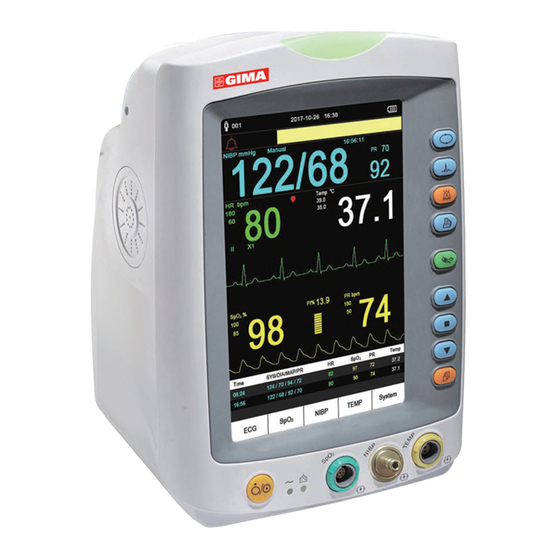
User Manual for Vital Signs Monitor Chapter 4 Operations This chapter mainly introduces display screen and operating instruction, including initial screen, default screen, system menu, menu setup and data upload. Before operating the monitor, please refer to the related section for accessories connection. - Page 33 User Manual for Vital Signs Monitor Title line Prompt information area NIBP area Heart rate area Temperature area ECG Waveform area area Plethysmogram Recent data list area Menu Figure 4.2A Default monitoring screen (monitor with ECG function) Title line: " Adult 001": the patient type and ID number of the patient being monitored currently. ²...
- Page 34 User Manual for Vital Signs Monitor The current time Measurement mode NIBP label and unit Pulse rate value Systolic pressure value Diastolic pressure value Mean arterial pressure Figure 4.2B NIBP panel ² "NIBP":the label of blood pressure. "122" is the systolic pressure value, "68" is the diastolic pressure value, and "92"...
- Page 35 User Manual for Vital Signs Monitor Pulse rate label and unit Label and value of perfusion index label High and low alarm Pulse rate value limit setting for SpO High and low alarm value Pulse intensity bar graph limit setting for Pulse rate Figure 4.2E SpO panel Waveform area...
-
Page 36: Screen For Real-Time Ecg Waveform (Optional)
User Manual for Vital Signs Monitor Note: 1. If the device is re-started, the data in recent list data area will be cleared. 2. Invalided value will be display as "--" Key Operation instruction: Short pressing display view " " key to shift screen views. Ø... -
Page 37: Screen Display For Ecg Waveform Recall (Optional)
User Manual for Vital Signs Monitor Short pressing Lead " " key to shift the ECG lead. Ø Short pressing Up/Down(" " / " " ) key to change ECG waveform gain. Ø Short pressing Print " " key to start / stop printing real-time ECG waveform. Ø... -
Page 38: Nibp List Screen (Optional)
User Manual for Vital Signs Monitor selected ECG waveform. Press “ ” key or “ ” key to scroll the ECG waveform forward / backward. Press print " " key to print the selected ECG waveform record. Ø Long pressing OK " "... -
Page 39: Spo 2 Data List Screen (Optional)
User Manual for Vital Signs Monitor Short pressing print " " key to print the current NIBP list. Ø Long pressing OK " " key, then a dialog of deleting records pops up, the user can delete all NIBP data Ø... -
Page 40: Trend Graph Display (For Hr Option)
User Manual for Vital Signs Monitor Figure 4.8 Alarm event list In this screen, the first column is the time the alarm occurs (format is mouth-day hour:minute), the second column is the event description, the third column is the onset value, and the fourth column is the high/low limit value. -
Page 41: Setup Menu Screen
User Manual for Vital Signs Monitor can press up “ ” key or down “ ” key to move the vertical cursor, the list box below will display /HR value and the time value at the point where the cursor stays. Move cursor back and forth this way, you can view the SpO /HR trend (12/24/96 hours long). -
Page 42: Ecg Setup (Optional)
User Manual for Vital Signs Monitor Instruction description: u Key operation: 1. Short pressing “ ” key or “ ” key to shift cursor to corresponding functional group setting. 2. Short pressing “ ” key to confirm and enter into corresponding functional parameter setup screen. 3. - Page 43 User Manual for Vital Signs Monitor "Lead": set ECG lead. ² "1mV": the activation status of the internal 1mV calibration signal. Select "On" means activation of the ² internal 1mV calibration signal, select "Off" means deactivate it. "On" means the ECG signal source will be the internally generated 1mV signal for calibration, and the calibration signal waveform (1mV, 1Hz square wave) will be displayed on the screen.
-
Page 44: Spo Setup (Optional)
User Manual for Vital Signs Monitor 4.9.2 SpO Setup (Optional) Pressing "SpO " button on the lower left of the default screen to enter into SpO setting screen, as shown in figure 4.11. Figure 4.11B SpO Setup Screen Screen Description: ²... - Page 45 User Manual for Vital Signs Monitor Figure 4.12 NIBP Setup NIBP Setup Screen Description: ² “SYS alarm high”: high alarm limit setting for systolic pressure. ² “SYS alarm low”: low alarm limit setting for systolic pressure ² “DIA alarm high”: high alarm limit setting for diastolic pressure. ²...
- Page 46 User Manual for Vital Signs Monitor change to display label "STAT" prompting the current NIBP mode, therefore the MAP value will not be displayed. When the "STAT" mode (at most lasting 5 minuter) finishes (or measurement error occurs or it is interrupted manually), then the device will shift into "Manual" mode automatically. ²...
- Page 47 User Manual for Vital Signs Monitor Figure 4.14 Hemostat setup screen Hemostat Setup Screen Description: ² “Pressure”: when you use hemostat function, you need to preset a cuff pressure for hemostasis. The pressure is adjustable, and its adjusting limit is different for different patient category: for neonates: preset range: 70~100 mmHg, default value: “90”...
-
Page 48: Temp Setup (Optional)
User Manual for Vital Signs Monitor In NIBP setup screen, short pressing " " key to select measuring mode. Press NIBP measuring " " key to confirm the setting and exit from setup screen. Short pressing display view " " key to exit. Press up/down key to select patient type. -
Page 49: Patient Info
User Manual for Vital Signs Monitor 4.9.5 Patient Info Figure 4.17 Patient Info. setup screen Screen description: “Patient ID”: change or set current patient’s ID number, 0~100 adjustable; Once the patient ID is ² changed, the history data in trend graph will be cleared, and the parameter settings will be resumed to default value. -
Page 50: Network Setup
User Manual for Vital Signs Monitor Output level Duration Output (format) High Continuous Pulse High Continuous Pulse ² “Source Hi_ALM / Source Mi_ALM / Source Lo_ALM”: three kinds of alarm sources can trig the nurse call: high level alarm, medium level alarm and low level alarm (multi-optional). After selecting the responding alarm level, the device will send out the nurse call signal according to "Source"... -
Page 51: System Setup
User Manual for Vital Signs Monitor 4.9.8 System Setup Figure 4.20 System Setup Screen Screen Description: ² “Alarm Vol.”: set alarm volume, “1~10” level adjustable, the factory default is 05. It is recommended that the alarm volume shouldn’t be adjusted lower than the factory default value unless the nursing personnel keeps close attention and surveillance on the patients and the device at all times. -
Page 52: Alarm Settings
User Manual for Vital Signs Monitor the tone frequency of pulse beep (sound becomes sharper); The lower the SpO value is, the lower the tone frequency of pulse beep (sound becomes flatter). ² "Color": to set the displaying color for each parameter (such as for SpO and NIBP). -
Page 53: Chapter 5 Alarm
User Manual for Vital Signs Monitor Chapter 5 Alarm 5.1 Alarm Priority Low Priority: NIBP over range Temp over range ECG Lead off Probe off Temp Probe off NIBP error message error message Medium Priority: HR/PR over range High Priority: ECG Arrest Ventricular Run Ventricular fibrillation... -
Page 54: Alarm Reset And Silence
User Manual for Vital Signs Monitor Audible Alarm Indication The audible alarm has different tone pitch and on-off beep patterns for each priority category. These are summarized in the table below. Alarm Category Tone Pitch Beep Chain High priority alarm ~400Hz 10 beeps pause 3 sec. -
Page 55: Verifying Alarm Function
User Manual for Vital Signs Monitor message descriptions and numerical flash and so on will be shown respectively and simultaneously on the screen. It is suggested that the users should not change the alarm volume lower than the factory default setting if close and constant attention could not be paid to the patient, otherwise the negligence of alarm event might cause irreversible harm to the patient. -
Page 56: Chapter 6 Technical Specifications
User Manual for Vital Signs Monitor Chapter 6 Technical Specifications 6.1 NIBP Monitoring 1. Measuring method: Oscillometric Technique 2. Pneumatic pressure measuring range: 0 mmHg~300mmHg 3. Accuracy of pressure measurement: ±3 mmHg 4. Cuff inflation time: <10 seconds (typical adult cuff) 5. -
Page 57: Data Recording
User Manual for Vital Signs Monitor 3. TEMP responding time: ≤150s for KRK sensor; ≤40s for YSI sensor 6.5 Data Recording 1. Sensitivity selection tolerance: ±5% 2. Recording speed: 25mm/s 3. Recording speed accuracy: ±10% 4. Hysteresis: ≤0.5mm 5. Frequency response: 0.5~40Hz for normal mode, 0.05~40Hz for enhanced mode. 6. - Page 58 User Manual for Vital Signs Monitor Heart rate alarm condition delay time: ≤10 sec 7. Response time to change in heart rate: Change from 80 bpm to 120 bpm: < 8 sec Change from 80 bpm to 40 bpm: < 8 sec 8.
-
Page 59: Guidance And Manufacturer's Declaration-Electromagnetic Compatibility
User Manual for Vital Signs Monitor 6.10 Guidance and manufacturer’s declaration-Electromagnetic compatibility Table 1 Guidance and manufacturer’s declaration-electromagnetic emission for all EQUIPMENT AND SYSTEM Vital Signs Monitor is intended for use in the electromagnetic environment specified below. The customer or the user of the equipment or system should assure that it is used in such an environment. Emissions test Compliance Electromagnetic environment-guidance... - Page 60 User Manual for Vital Signs Monitor Table 2 Guidance and manufacturer’s declaration-electromagnetic immunity for all EQUIPMENT AND SYSTEMS Vital Signs Monitor is intended for use in the electromagnetic environment specified below. The customer or the user of the equipment or system should assure that it is used in such an environment. Electromagnetic environment Immunity test...
- Page 61 User Manual for Vital Signs Monitor Table 3 Guidance and manufacturer’s declaration – electromagnetic immunity-for EQUIPMENT and SYSTEM that are not LIFE-SUPPORTING Vital Signs Monitor is intended for use in the electromagnetic environment specified below. The customer or the user of Vital Signs Monitor should assure that it is used in such an electromagnetic environment. Compliance IMMUNITY test IEC 60601 test level...
- Page 62 User Manual for Vital Signs Monitor Table 4 Recommended separation distances between portable and mobile RF communications equipment and The equipment or system- for EQUIPMENT and SYSTEM that are not LIFE-SUPPORTING Vital Signs Monitor is intended for use in an electromagnetic environment in which radiated RF disturbances are controlled.
-
Page 63: Chapter 7 Packaging And Accessories
User Manual for Vital Signs Monitor Chapter 7 Packaging and Accessories 7.1 Packaging The product is packed in high quality corrugated cartons with foam inside to protect the equipment against damage in the shipping and handling process. Weight: Details see the indication on the outer package. Dimension: 360(L)×320(W)×410(H) (mm) 7.2 Accessories (1) NIBP cuff... -
Page 64: Chapter 8 Monitoring Parameter
User Manual for Vital Signs Monitor Chapter 8 Monitoring Parameter 8.1 NIBP Monitoring 8.1.1 Measuring Principle Blood pressure may be measured in an invasive way (whereby the sensor will be inserted into blood vessel directly) or a non-invasive way. The non-invasive way includes several methodologies, such as the Korotkoff Sound Method and oscillating method. -
Page 65: Factors Affecting Nibp Measuring
User Manual for Vital Signs Monitor the Korotkoff Sound Method in less error, higher reliability and stability. Their differences may be reflected in the following aspects. 1. The measures by the Korotkoff Sound Method are liable to effect of human factors. For example, different people may have different sound judging ability, or different reactivity when listening to heart sound and reading mercury meter. -
Page 66: Spo Monitoring
User Manual for Vital Signs Monitor 1. Serious angiospasm, vasoconstriction, or too weak pulse. 2. When extremely low or high heart rate or serious arrhythmia of the subject occurs. Especially auricular fibrillation will lead to unreliable or impossible measurement. 3. Do not take the measurement when the subject is connected with an artificial heart-lung machine. 4. -
Page 67: Low Spo Measuring Value Caused By Pathology Reason
User Manual for Vital Signs Monitor There is an arterial occlusion proximal to the sensor ² Blood vessel contraction caused by peripheral vessel hyperkinesias or body temperature decreasing ² 8.2.3 Low SpO measuring value caused by pathology reason Hypoxemia disease, functional lack of HbO ²... - Page 68 User Manual for Vital Signs Monitor infrared heater, and direct sunlight etc. Strenuous action of the subject or extreme electrosurgical interference may also affect the accuracy. ² Please do not use the SpO sensor when having the MRI, or burn may be caused by faradism. ²...
-
Page 69: Chapter 9 Troubleshooting
User Manual for Vital Signs Monitor Chapter 9 Troubleshooting 9.1 No Display on the Screen Shut down the machine and unplug the power. Use a universal meter to check if the outlet has proper voltage, if the power cable is in good condition, and if the power cable is properly connected with this apparatus or outlet. Remove the fuse from the back cover of this machine, and make sure it is in good condition. -
Page 70: Chapter 10 Maintenance
User Manual for Vital Signs Monitor Chapter 10 Maintenance 10.1 Service and Examination 10.1.1 Daily Examination Before using the monitor, the checks below should be carried out: Check the monitor for any mechanical damage; Inspect the exposed parts and the inserted parts of all the leads, and the accessories; Examine all the functions of the monitor that are likely to be used for patient monitoring, and ensure that it is in good working condition;... -
Page 71: Service
User Manual for Vital Signs Monitor ² Do not use this battery on other devices; ² Do not use this battery below -10 ℃ or above 40 ℃ ; ² Dispose of the battery, the local law should be followed. % In order to maintain battery supply time and prolong battery lifetime, please charge the battery every one or two months if don’t use battery for a long time. -
Page 72: Cleaning And Disinfection Of Accessories
User Manual for Vital Signs Monitor % Do not pour the disinfector on its surface while disinfecting. 10.3 Cleaning and Disinfection of Accessories It is recommended to clean the accessories (including sensor, leads and plugs) with a piece of gauze which has been soaked in 75% Alcohol or 70% Ispropanol before use. -
Page 73: Chapter 11 Appendix
User Manual for Vital Signs Monitor Chapter 11 Appendix 11.1 Prompt information explanations Mute C-D: XXX seconds Alarm silence count down: XXX seconds NIBP C-D: XXX seconds NIBP auto measuring cycle count down: XXX seconds TOUR C-D: XXX seconds Hemostat alert count down: XXX seconds Probe off probe fells off PR over limit... -
Page 74: Default Alarming Values And Setup Range
User Manual for Vital Signs Monitor 11.2 Default Alarming Values and Setup Range The default alarming value: Mode Adult Pediatric Neonate Parameter High limit 180mmHg 130mmHg 110mmHg Low limit 60mmHg 50mmHg 50mmHg High limit 120mmHg 90mmHg 90mmHg Low limit 50mmHg 40mmHg 30mmHg High limit... -
Page 75: Accessories List
User Manual for Vital Signs Monitor 11.3 Accessories List Part No. Part Name Remark 15044051 Adult SpO Finger clip sensor 15044061 Adult SpO Finger rubber sensor Optional 15044041 Pediatric SpO Finger clip sensor Optional 15044063 Neonate SpO Y-type sensor Optional 15024402 Adult NIBP cuff(25~35cm) 15021402... -
Page 76: Instructions For Spo Probe
User Manual for Vital Signs Monitor 11.4 Instructions for SpO Probe Instructions for Pediatric SpO Finger Clip Sensor Intended Use When used with a compatible patient monitor or a pulse oximeter device, the sensor is intended to be used for continuous, non-invasive functional arterial oxygen saturation (SpO ) and pulse rate monitoring for pediatric patients weighing between 10~40kg. - Page 77 User Manual for Vital Signs Monitor Carefully route cables to reduce the possibility of patient entanglement or strangulation. Do not alter or modify the sensor. Alterations or modifications may affect performance or accuracy. 10) Do not use the sensor if the sensor or the sensor cable appears damaged. Instructions for Adult SpO Finger Rubber Sensor Intended Use...
- Page 78 User Manual for Vital Signs Monitor not use the sensor during MRI scanning. Carefully route cables to reduce the possibility of patient entanglement or strangulation. Do not alter or modify the sensor. Alterations or modifications may affect performance or accuracy. Do not use the sensor if the sensor or the sensor cable appears damaged.
- Page 79 User Manual for Vital Signs Monitor interrupted by NIBP cuff or circulatory patient condition will result in no pulse found or loss of pulse. Do not use the sensor or other oximetry sensors during MRI scanning. Carefully route cables to reduce the possibility of patient entanglement or strangulation. Do not alter or modify the sensor.
- Page 80 Disposal: The product must not be disposed of along with other domestic waste. The users must dispose of this equipment by bringing it to a specific recycling point for electric and electronic equipment. GIMA WARRANTY TERMS The Gima 12-month standard B2B warranty applies.
Need help?
Do you have a question about the PC-900PLUS SNET and is the answer not in the manual?
Questions and answers