Table of Contents
Advertisement
Quick Links
Advertisement
Table of Contents

Related Manuals for Gima PC-8000Pro


Summary of Contents for Gima PC-8000Pro
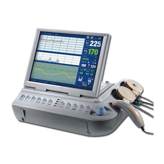
- Page 1 Name: Obstetric Monitor Model: PC-8000Pro Type: Single Fetal Monitor 29550 ATTENTION: The operators must carefully read and completely understand the present manual before using the product. GIMA S.p.A. Via Marconi, 1 20060, Gessate (MI) Italy Made in P.R.C. M-29550-GB-Rev.2.10.15...
-
Page 2: Table Of Contents
TABLE OF CONTENT Introduction ..........................- 1 - Description of System ......................... - 3 - Intended Use ..............................- 3 - Configuration and Principal Characteristics: ..................- 3 - Functional Description ....................... - 5 - 3.1 Front View of the Equipment....................... - 5 - 3.2 Back of the Equipment ........................... - Page 3 6.1 Main Interface of the Fetal Maternal Monitor ................- 24 - 6.1.1 Message/Main menu Area ..................- 25 - 6.1.2 Waveform Area ......................- 26 - 6.1.3 Parameter /Alarm Area .................... - 26 - 6.1.4 Status /Time zone Area..................... - 27 - 6.1.5 Network ........................
- Page 4 6.9 Sever ................................. - 47 - 6.10 maintenance ............................- 47 - 6.11 About ..............................- 48 - 6.12 Records ..............................- 49 - 6.13 Switch ..............................- 50 - 6.14 NST timer(Optional) .......................... - 51 - 6.15 Doctor Remark ............................ - 52 - Pre-Monitoring Preparation ....................
- Page 5 9.1.3Preparation of the Contacting Area on Skin ............- 63 - 9.1.4 Menu Setup ........................- 65 - 9.1.5 Alarm setup ........................- 65 - 9.6 Maternal RESP Monitoring ......................... - 65 - 9.6.1Principle ......................... - 65 - 9.6.2 Operation ........................- 65 - 9.7 SpO / Pulse Monitoring ........................
- Page 6 11.1.6Cleaning of the Recorder ..................- 76 - 11.2Detergents ............................. - 76 - 11.3Sterilization ............................- 77 - Troubleshooting ........................- 78 - Guarantee ..........................- 81 - 13.1Manufacture, Safety, Reliability and Performance ..............- 81 - 13.2Service ..............................- 81 - 13.2.1 Procedure of Return ....................
-
Page 7: Introduction
1 Introduction This handbook explains how to install, use, maintain and clean the fetal maternal monitor. To ensure the safety of the patients,this apparatus must be used under the supervision of a doctor or a nurse. In case of failure, the technical staff of breakdown service will occur by telephone or repairs will be ensured on site by us or the system will be turned over for repair, according to the opinion of our company... - Page 8 To ensure the safety and the curative effect of a patient, use the accessories recommended by the manufacturer. If not, the patient can be wounded or curative effects can be reduced. If a portable monitor falls accidentally it is not more available for the use, you must supervise its results attentively, to continue to use the monitor that when the results of measurements in conformity with the standard.
-
Page 9: Description Of System
2 Description of System The fetal maternal monitor is a non-invasive perinatal monitoring system of measurement and to post the contractions the uterus and fetal heartbeat rate on a nonpermanent screen graph and possibly on a diagram recorder. This information is used to help to evaluate the wellbeing of the fetus during the last quarter of the pregnancy (not-stress test). - Page 10 NST Report Option Option Option Option HMDI Option Option Option Option Keyboard/mouse Option Option Option Option Touch screen Option Option Option Option A fetal stimulator can be provided to give a mild vibrating stimulation to the fetus. A TCP/IP interface is built in the monitor. With it, the series monitors can be connected to a CNS central nurse station via LAN network.
-
Page 11: Functional Description
3 Functional Description 3.1 Front View of the Equipment. Figure 1 Front view 1. Printer 2. Toco transducer 3. Ultrasound (FHR) transducer 4. Marker of the fetal movements During the normal use of the monitor, keep the door of the printer closed and locked to avoid the deterioration of the performance of the printer. -
Page 12: Back Of The Equipment
3.2 Back of the Equipment Figure 2 Rear panel 1. Port HDMI 2. Network (TCP/IP)/USB (option) 3. Handle 4. Earthing 5. Ventilator 1. VGA (CRT): Support to connect fetal monitor to external color VGA monitor a) Operating mode: 1024 × 768, 256 colors b) Signal: Analogical RGB 0,7 Vcc/750 Ohm Hor. -
Page 13: Left Side Of The Equipment
3.3 Left Side of the Equipment Figure 3 left-side view 1. Socket-outlets: A connector used to connect the electrical supply networks. Connect the power AC in strict conformity with chapter 5.3 of the handbook. Ensure that the input AC power is similar to the requirements of the product. If not, use the equipment supplied with battery. -
Page 14: Front Panel Of The Equipment
3.5 Front Panel of the Equipment Figure 5 Front panel of the equipment-control panel 1. LCD screen: 12.1 inches (31cm) TFT true color screen LCD, rotation at the interior of 0-90 degrees 2. Transducer Support for temporary detention of ultrasonic transducer, transducers Toco and marker of the fetal movements. -
Page 15: Bottom Part Of The Equipment
3.6 Bottom Part of the Equipment Figure 6 Bottom view of the equipment 1. Wall mount hole: User can use the screwdriver to break the holes reserved on the bottom panel and then install the wall mount as indicated in chapter 5.10 2. - Page 16 1. “ON/OFF: Press on this button to Switch on or off the monitor 2. + (volume): to increase the volume of the fetal heartbeat sound, the volume status icon showed on the bottom right of the screen. 3. - (volume): To decrease the volume of the fetal heartbeat sound, the volume status icon showed on the bottom right of the screen.
- Page 17 ”PRINT “:Printing indicator. It shows green light when printing. It shows green light when printing. 8. “Silence”: Disable/Enable audio alarm. Press this key once to switch the alarm sound off, and there will be an icon" "on top right of the screen. But the alarm information displays and indicator flashes as normal;...
- Page 18 13. Control Knob (encoder): Anti-clockwise rotation or clockwise rotation to select, page up/down, to confirm and the displacement of the cursor, support above to confirm your choice or in the sub-menu. All operations on the screen or in the menu can be completed by using the control knob.
-
Page 19: Safety
4 Safety Configuration of the monitor conforms to the international requirements of safety for medical electrical appliance, such as IEC60601-1, IEC60601-2-37, IEC60601-1-2, IEC60601-1-4, IEC60601-1-8 and IEC60601-1-8. Do not connect several monitors when using, otherwise it may cause cumulative leakage which may raise risk of electric shock to the patient or the operator. -
Page 20: Grounding Monitor
4.2Grounding Monitor To protect the patients and the medical personnel, the monitor must be grounded. For this reason, the monitor is equipped with a detachable triplex cable, and is grounded via the ground wire (protective ground) of power line once the cable is inserted into the match three-pin socket. -
Page 21: Condensation
To protect the patients and the medical personnel, the device must be grounded. For this reason, the monitor is equipped with a detachable three-pin cable, and is grounded by an intermediary wire (protective ground) of power line once the cable is connected to a three pin socket. - Page 22 The disposable material or accessory of equipment for the monitor must be used for only one patient. The disposable materials or accessories should be abandoned immediately, and they should not be re-used or discarded at random. They must be treated in conformity with the local State or payments Do not withdraw the batteries if the apparatus is powered by the battery The accessories and the sensor do not contain any emulsion...
-
Page 23: Installation
5 Installation 5.1 Unpacking Before opening the package, check the package box first. If the box is damaged, do not open the parcel, and contact the service engineer of supplier immediately. Take out the material and the accessories from the box. Preserve packing for transport or possible future storage. -
Page 24: Power Supply
ECG Cable 5 leads — — Electrode plate (bag) 25 pieces in one bag — — TEMP Sensor 8189007072, 2.25K — — 8111810022, □ Paper width 150mm, 150P Printer Paper (pad) 8111810003,□ Paper width: Option Option Option Option 112mm, 150P, Ultrasound gel 8190100001, Bottle Rechargeable... -
Page 25: Boot
Regarding equipping the batteries, the battery capacity may be decreased due to the long journey or storage, it is therefore necessary to charge the battery before use. In this way, the device may not work properly due to the deficient power if you start the device without connecting to AC power supply. -
Page 26: Connection Of The Transducer
paper holder in its initial position until you hear sound of two clicks, which indicates the door is closed. Output information from printer includes patient information, parameter list, record time, waveform and etc. Figure 9 Print How to close the printer cabinet: Press both side of printer cabinet simultaneously, and you will hear two “ka”... -
Page 27: Test Of Ultrasound Transducer
Please choose the good sensor according to the accessory list listed in the. Improper Sensor can lead to the reduction of safety and performance 5.7 Test of Ultrasound Transducer This 12-crystal, broad beam US transducer is used for monitoring fetal heart rate (FHR). The US transducer operates at a frequency of 1.0MHz. -
Page 28: Test Of Event Maker
Figure 8 fast tests Toco transducer 5.9 Test of Event Maker The fetal Movement Marker is a hand-hold device used by the pregnant woman to detect fetal movement from the mother’s feeling. Press and then slacken the marker, you will hear a “di” sound, and a marker " "... - Page 29 blocking the view of LCD data display. The wall-mounted support should be installed parallel to the ground. Once the wall-mounted support is fixed, knock off the four wall-mounted holes on the base of monitor with screwdriver and point them to the protuberant post on the support, and then press the support and draw it downwards to lock it with the monitor.
-
Page 30: Operation
6 Operation 6.1 Main Interface of the Fetal Maternal Monitor Below shows the screen of the fetal maternal monitor Figure 11 Main Interface (Single fetus monitoring) - 24 -... -
Page 31: Message/Main Menu Area
Figure 12 Main Interface (Twins fetus monitoring) The screen of the Fetal maternal monitor is divided into four fields: Message/Main menu area Waveform area Parameter/alarm area Status/Time zone area. 6.1.1 Message/Main menu Area Zone of Message/main menu area is on the left top of the screen, which posts the current status of the monitor and the patient. - Page 32 6.1.2 Waveform Area The waveforms displayed in the area are for the fetal heart rate (FHR), the pressure of the uterine contractions (TOCO) and the movements of the fetus (FM), maternal ECG, SpO RESP. Up to 6 waveforms can be displayed at the same time. The waveforms from top to bottom are: FHR1 (FHR2), TOCO, ECG, SpO , and RESP.
-
Page 33: Network
6.1.4 Status /Time zone Area Status/time zone of the system is located at the right top of the screen to display the status of alarm sound, printer, network, and battery/AC input and system time. 1) The status of the alarm sound: It indicates the sound status of monitor’s speaker (mute or volume on). -
Page 34: Main Menu
6.2 Main menu Press the encoder to enter into menu setting as follows. (If armed with touch screen, please click the icon: then it will pop up the main menu.) Notice: If the monitor armed with touch screen, you can use finger or touch pen to click it, it has the same functions which we introduce in this manual. - Page 35 Figure 13 patient information Search Scope: All, Last month, Last three month, Last six month, Last year. Then choose searching keyword via ID, Phone or Name and fill in the information. When the cursor moves to the blank, the background turn into blue, when you click it , the keyboard will pop up as follows.
-
Page 36: Freeze
Register the patient’s first test information You can input the patient information: Name, Mobile Phone, Age, Weeks, and Hospital information, like ID, Bed ID and Note. When selected one registered case, you can choose “delete” or “Modify” to delete or modify When you click the “Monitor”... -
Page 37: Configuration
6.5 Configuration This menu will show all parameter settings and other information about the monitor. 6.5.1 Fetal Monitor Parameter Figure 14 fetal monitor setting Fetal Monitor Setting Display Scan Speed: 1, 2, 3 cm/min Display FM wave: when ticked, it will display on the screen. Display Toco wave: when ticked, it will display on the screen. -
Page 38: Ecg Parameter
6.5.2 ECG Parameter Figure 15 ECG setting ECG Setting Display Lead Type: 3leads, 5 leads. Scan Speed: 6.25mm/s, 12.5mm/s, 25mm/s. Gain: 0.25, 0.5, 1, 2. Channel 1: I, Ⅱ, Ⅲ, AvR, AvL, AvF, V. Channel 2: I, Ⅱ, Ⅲ, AvR, AvL, AvF, V. Channel 3: I, Ⅱ, Ⅲ, AvR, AvL, AvF, V. -
Page 39: Nibp Parameter
ST analysis: when ticked, it will conduct ST-segment analysis. Arrhythmia Analysis: When ticked, it will conduct arrhythmia analysis. 6.5.3 NIBP Parameter Figure 16 NIBP Setting NIBP Parameter NIBP Work Mode: MANL, Auto, STAT. Auto mode interval: 1-99 minutes. Unit: mmHg, KPa. - 33 -... -
Page 40: Spo2 Parameter
6.5.4 SpO2 Parameter Figure 17 SpO2 setting SpO2 Setting SpO2 Scan Speed: 12.5mm/s, 25mm/s, 50mm/s. Fill: when ticked, the waveform will display in a form of filling mode. BKG tile: when ticked, the SpO2 waveform area will show background tile. - 34 -... -
Page 41: Resp Parameter
6.5.5 RESP Parameter Figure 18 RESP Setting RESP Setting RESP Scan Speed: 6.25mm/s, 12.5mm/s, 25mm/s. Gain: 0.25, 0.5, 1, 2. RESP Lead: RA-LL, RA-LA. Fill: when ticked, the waveform will display in a form of filling mode. BKG: when ticked, the RESP waveform area will show background tile. RESP Resist Drifting: when ticked, it will enable to resist drift. -
Page 42: Description Of Alarm
Please carry out sufficient alarm settings for each patient to avoid treatment delay. At the same time, you should ensure the alarm can send out alarm sounds Set alarm limits according to the clinical situations of each patient. The setup of alarm limit is important and the alarm limits shall be carefully selected according to the recognized clinical practice. -
Page 43: Silence Of Alarms
Zone of showing technical alarm and patient alarm: the flashing background with texts indicates the alarm. For example, the background with texts of “Heart rate too high” indicates medium alarm. Level of alarm Alarm visual Audible alarm High Indicator flash flickering 3 aural signals every 8 seconds quickly... -
Page 44: Fetal Monitor Alarm
6.6.6 Fetal Monitor Alarm Figure 19 fetal monitor alarm setting Fetal Monitor Alarm Setting Data FHR Over Range Alarm: When ticked, if the FHR value exceeds the range, it will give the relating alarms. Normal Min: 30-239 bpm. Normal Max: 31-240 bpm FHR Overlap: When the monitor is for twins, you should tick it, when the twins have the same FHR value, it will give alarms. -
Page 45: Ecg Alarm
6.6.7 ECG Alarm Figure 20 ECG Alarm setting ECG Alarm Setting Data HR Over Range Alarm: when ticked, if the HR value exceeds the defined range, it will give the relating alarms. Normal Min: 10-299 bpm, Normal Max: 11-349 bpm ST Over Range Alarm: when ticked, if the ST value exceeds the defined range, it will give the relating alarms. -
Page 46: Nibp Alarm
6.6.8 NIBP Alarm Figure 21 NIBP setting NIBP Alarm Setting Data Sys Over Range Alarm: when ticked, if the systolic pressure exceeds the defined range,it will give alarms. Normal Min: if the patient is adult, it can set: 40~269 mmHg if the patient is child, it can set: 40~199 mmHg if the patient is Neonate, it can set: 40~134 mmHg Normal Max: if the patient is adult, it can set: 41~270 mmHg... -
Page 47: Spo2 Alarm
Normal Max: if the patient is adult, it can set: 11~210 mmHg if the patient is child, it can set: 11~150 mmHg if the patient is Neonate, it can set: 11~95 mmHg Mean Over Range Alarm: when ticked, if the systolic pressure exceeds the defined range,it will give alarms. -
Page 48: Resp Alarm
Normal Min: 0-99 Normal Max: 1-100 PR Over Range Alarm: when ticked, if the PR value exceeds the defined range,it will give alarms. Normal Min: 25- 249 bpm Normal Max: 26-250 bpm Sensor Off or Finger Off Alarm: when ticked, it will give alarms if the sensor is off or the finger is off. -
Page 49: Temp Alarm
Apnea Time: 1-60 seconds Sensor Lost Alarm: When ticked, if the sensor is off, it will give alarms. 6.6.11 TEMP Alarm Figure 24 TEMP setting TEMP Setting Unit TEMP unit: ℃, ℃ Data TEMP Over Range Alarm: when ticked,if the temperature exceeds the defined value, it will give alarms. -
Page 50: Print
6.7 Print All printing parameters can set according to this menu, if you want to print other report except fetal monitor report, you should check it before printing. Figure 25 Print Print Setting Report Type: Fetal Monitor report, vital signs report General Print Speed: 1, 2, 3cm/min Print time: 1-99 minutes... -
Page 51: 1Nst Report Fuction(Optional)
6.7.1NST Report Fuction(Optional) The fetal monitors can be equipped with NST (Non Stress Test) Report function (option) based on advanced Fischer evaluation method to give a score of fetal wellbeing after 20 minutes continuous monitoring, thus helping the doctors make judgment about fetal health condition. -
Page 52: System
6.8 System This menu will show you how to set system parameter. Figure 27 System setting System Setting Vital Signs Patient type: ADLT, Pediatric and Neonate. Date& Time Current Date: Set the current date. Current Time: Set the current time. Format Date Format: YYYY-MM-DD,MM/DD/YYYY,DD/MM/YYYY Use the 24 hours format: when ticked, the system will use 24-hours format. -
Page 53: Sever
6.9 Sever If you want to set a CMS (Central Monitoring System), then you should set this menu. The CMS is a set of integrated management software. It can save time and human labour. Figure 28 Sever Network Setting Bed ID ID: 1-245, it should be different from each bed and also different from other network instruments. -
Page 54: About
Figure 29 factory setting 6.11 About This Item shows the monitor’s all hardware and software configurations. Figure 30 About - 48 -... -
Page 55: Records
6.12 Records The screen will show the current monitoring case’s records, you can use “Choose” icon to enter into the patient information menu to choose the case which you want to check. When enter into patient information menu, you can manage the patient’s information. Figure 31 Records History Record List All the historic records can be checked here. -
Page 56: Switch
Time length: 1-99 min Current time: When ticked, the printing will start from the current time, or it will begin from the initial time. Start time: set the print start time. NST Report Preview: Previewing the selected records’ NST report. When ticking it, the preview interface will be displayed. -
Page 57: Nst Timer(Optional)
6.14 NST timer(Optional) If you want to start NST timer, you can choose it, then the following dialog will show. After you choose the time, the counter will work after 15 seconds. Figure 33 NST timer After the time is out, it will give the relating alarms to remind the doctor or nurse. - 51 -... -
Page 58: Doctor Remark
6.15 Doctor Remark Select this menu to mark the event, when you mark one event, it will appear on the screen and print out on the paper. And marked information will also be stored in the records. You can pre-store the events by adding new mark; this will be very convenient to mark the event. -
Page 59: Pre-Monitoring Preparation
7 Pre-Monitoring Preparation 7.1 Switching On the Monitor ♦ Turn the monitor on and verify that the normal monitoring screen appears on the display. Remove the monitor from service if an error occurs. ♦ Determine whether the monitor is powered from internal battery or the battery eliminator. - Page 60 Figure 36-1 Connecting the transducer Figure 36-2 Disconnecting the transducer Check for visible damages of the transducers every time before connecting them to the monitor. Pay special attention to the cracks on the transducers and cables before immersing them into conductive fluid. If damage is found, replace them with good ones at once.
-
Page 61: Fetal Monitoring
8 Fetal Monitoring 8.1Confirming Fetal Life Fetal heart rate is measured by placing an ultrasound transducer on the maternal abdomen and processing the Doppler echo signal to produce a heart rate and an audio representation of the echo signal. The monitoring of heartbeat rate of the fetus by echography is recommended after the 28th week of pregnancy for non-stress or routine fetal monitoring. - Page 62 Measure TOCO Measure Figure 37 Ultrasound transducer & TOCO transducer positioning (single fetus) 3) Monitoring Twin FHRs To monitor twin FHRs externally, you need connect an US transducer to US1 socket and the second US transducer to US2 socket of the monitor. Follow the instructions described in Section 8.2.2 to acquire FHR signals for both channels.
- Page 63 may be more comfortable to the mother. 5) It is not possible to measure FHR unless an audible fetal heart signal is present. The fetal pulse can be distinguished from the maternal pulse by feeling the mother’s pulse during the examination. It is suggested that, except particular required by clinicians, 20-30 minutes of fetal monitoring is sufficient to obtain data of information useful.
-
Page 64: Alarm
8.3 Alarm You can set the FHR alarm via the alarm setup menu, which includes setting alarm switch, regulating the upper/lower limit of alarm, etc. Conditions of occurrence of alarm: alarm is activated when the FHR exceeds the limit of alarm. -
Page 65: Monitoring Of The Uterine Activity
If you are monitoring externally, adjust one of the transducers’ position to find the second heart. fetal If you are monitoring internally, adjust the US transducer’s position to find the second fetal heart. 8.5 Monitoring of the Uterine Activity 8.5.1 Introduction Uterine activity is measured externally by placing a pressure sensitive device (Tocotonometer) on the maternal abdomen and recording relative pressure changes. - Page 66 The uterine activity reading at this point should be 30 ~ 90. A flat-top at lower than 100 units on the TOCO scale indicates the belt is too tight, you need to adjust it. Wipe off any gel presents on abdomen around this area. NOTES: 1) Do not apply Aquasonic coupling gel on a TOCO transducer or its contact area.
-
Page 67: Message Of Alarm
8.5.4 Message of Alarm Alarm, the cause and the extent of what can be posted in the uterine pressure controlet are presented at table 2. Table 2: alarm, Cause and the level Message of alarm Cause Level Pressure transducer The transducer is not connected to the disconnected monitor 8.6 Monitoring of the Fetal Movements... - Page 68 The patient marker icon is an upward point arrow. The monitor will display this upward pointing arrow in the information frame of the display. A strip chart printout of patient record will also show this mark. - 62 -...
-
Page 69: Maternal Monitoring
9 Maternal Monitoring 9.1Maternal ECG Monitoring 9.1.1Principle of ECG Measurement The electrocardiogram (ECG or EKG) is primarily a tool for evaluating the electrical events within the heart. The action potentials of cardiac-muscle cells can be viewed as batteries that cause charge to move throughout the body fluids. These currents represent the sum of the action potentials occurring simultaneously in many individual cells and can be detected by recording electrodes at the surface of the skin. - Page 70 The desired area of the skin may be gently polished in order to remove the thick rough skin and oil. Conductive gel may be apply to the area where the skin is not good conductive for the electrodes. To check the patient’s ECG signal, make sure the plates of electrodes are properly located on the body.
-
Page 71: Menu Setup
Figure 39 Electrodes positioning Note: Lead V [see chest electrodes above] may be located at any of the six positions as shown in the table above and the figure below (Points V1, V2, V3, V4, V5 and V6), in other words, the chest electrodes (Lead V ) should be located at only one of the six positions to be measured. -
Page 72: Spo / Pulse Monitoring
It’s very important to put the electrodes on the body properly, in order to get good RESP waveform, put the electrodes as figure 33 Figure 40 Electrodes positioning 9.7 SpO / Pulse Monitoring 9.7.1General Information Plethysmogram measurement is employed to determine the oxygen saturation of hemoglobin in the arterial blood. -
Page 73: Maternal Nibp Monitoring
a) The pulse oximeter sensor could cause skin irritation. Move the sensor to a different location if any skin irritation is present. b) The pulse oximeter sensor is light sensitive. Excessive ambient light makes it difficult for the system to provide accurate readings. Do not place the pulse oximeter sensor on the same extremity with the blood pressure cuff. -
Page 74: 3Measurement Steps
Figure 42 put the cuff properly Connect the cuff’s plug to the NIBP connector on the side panel, and make sure the connection is secure. Prior to use of the cuff, empty the cuff until there is no residual air inside it. -
Page 75: Temp Monitoring
If any doubt about the result, please measure the patient's blood pressure by a manometer first and compare the two results. Cuff will inflate up to 180mmHg at the first measurement. Check the patient type is appropriately selected at first measurement to avoid mistake of measurement and patient safety. -
Page 76: Maintenance
10 Maintenance 10.1 Maintenance Inspection (1) Visual Inspection Prior to every time use, do the following inspection: ♦ Check the monitor and accessories to see if there is any visible evidence of damage that may affect patient safety. Pay special attention to the cracks on the sensors and cables before immersing them into conductive fluid. -
Page 77: Maintenance Of The Battery
To carry out a daily inspection and routine maintenance on the monitor and its accessories in a normal way, although, while the methods of sterilization and disinfection must be strictly in conformity with the specifications of this handbook. The material must be placed at the good place, handled with prudence. -
Page 78: Maintenance Of The Belts
Do not autoclave. Do not sterilize with gas. Do not immerse in liquid. When using solutions, use sterile wipes to avoid pouring fluids directly on the sensor. 10.5Maintenance of the Belts Wash soiled belts with soap and water. The water temperature must not exceed 60℃ (140℉) 10.6 Maintenance of the Record Papers When storing recorder paper (including used paper with traces): Do not store in plastic envelopes. -
Page 79: Cleaning
11 Cleaning 11.1Cleaning Inspection In order to avoid infection, clean and disinfect the monitor and accessories after each use. 11.1.1Cleaning of the Monitor Regular cleaning of the monitor enclosure and the screen is strongly recommended. The solutions recommended for monitor cleaning are: soft soap water, Tensides, Ethylate and Acetaldehyde. -
Page 80: 2Cleaning Of The Accessories
Don’t remain any cleaning solution on the surface of the monitor. Avoid pouring liquids on the monitor while cleaning. The monitor surface can be cleaned with hospital-grade ethanol and dried in air or with crisp and clean cloth. We have no responsibility for the effectiveness of controlling infectious disease using these chemical agents. -
Page 81: Cleaning Of The Spo 2 Sensor
the rubber tube and the long side of the cuff are in a line, the rubber band will now be rolled up vertically and inserted into large open cuff, to hold the rubber tube and the cuff, jitter the cuff until the rubber band into place. And then pull the rubber tube into cuff, come out through the hole lining beneath. -
Page 82: 4Cleaning Of The Ecg Cables
Before cleaning, disconnect the SPO2 sensor and instrument. Before re-use after cleaning, it should be allowed to dry in the air Do not immerse the sensor cable in any liquid, do not use steam or ethylene oxide sterilization on the sensor Do not use high-pressure sterilization on the sensor If the sensor or cable is damaged or have deteriorated signs, re-use should be prohibited... -
Page 83: Sterilization
Caution: MANUFACTURER will not accept any legal responsibilities for possible medical contaminations caused by the suggestions to apply the above-mentioned cleaning agents or detergents for the purpose of cleaning this monitor. Please consult the official in your hospital or medical specialist in contaminations for further opinions before apply the above mentioned cleaning agents and detergents if you have any doubts. -
Page 84: Troubleshooting
12 Troubleshooting Prior to apply this monitor to the patient, the operator must check the following: To see if any mechanical damaged to this monitor and all accessories. To see if there’s any damaged cables leads and plugs. To make sure that all functions or operations which will be applied to the patient are functioning correctly and try to ensure the monitor in such good working order. - Page 85 right position. 3. Do zero TOCO default value (20). 4. Waiting for uterine contraction. 4. Mother uterine 5. Replace new sensor. contraction. 6. Loose belt a little. 5. Sensor damaged. 6. TOCO sensor highly sensitive. 1. Bad contact of ECG cable. 1.
- Page 86 1. Thermal paper is not put in 1. Adjust position and place of Printing deviation right place. thermal printer paper. Error printing 2. Used printer paper 2. Using correct paper. curve incorrect width. - 80 -...
-
Page 87: Guarantee
13 Guarantee 13.1Manufacture, Safety, Reliability and Performance We guarantee that the systems Fetal maternal monitor to be free of defects in workmanship and materials for a period of one (1) year after the installation, except following exceptions: ♦ The product is repaired or modified by unauthorized personnel ♦... - Page 88 NOTWITHSTANDING ALL CONTRARY DECLARATIONS CONTAINED IN THIS HANDBOOK, WE WILL NOT BE IN NO CASE HELD FOR PERSON IN CHARGE TOWARDS the PURCHASER OR a THIRD, FOR the PARTICULAR DAMAGE, ADDITIONAL, IMMATERIAL OR SPECIMENS OF WHICH NATURE THAT EC IS, Including, BUT WITHOUT BEING LIMITED To, the COMMERCIAL LOSS DUE TO an UNSPECIFIED REASON OR the COMMERCIAL INTERRUPTION OF WHICH NATURE THAT EC IS.
-
Page 89: Design Feature
14 Design Feature 14.1 Specifications Physical Specifications Dimension 35cm (W)*30cm (D)*11cm (H) Dimension Weight Weight standard configuration: 4 kg Power AC100-240V , 50/60Hz Operation requirements Environment Power 100VA Temperature 5-40℃ Humidity 30-93% non-condensing Fetal/Maternal Performance Specifications Display 12.1 inch (1024×768 pixel) color TFT –LCD Performance Specifications Indicator... - Page 90 Display update rate 0.25second Beat to bea change(max.) for 28bpm ultrasound US frequency 1MHz±5%Hz Measurement method Strain gauge sensor element TOCO Sensitivity 1 unit =2.5g Resolution 1 unit Measurement range 500 units Baseline setting 0, 5,10, 15, 20 can be selective Update rate 0.25 second Auto offset correction...
-
Page 91: Safety
Accuracy ±1bpm/ ±1% Leads I, II, III, aVL, aVR, aVF, V Sweep speed 12.5mm/s, 25mm/s, 50mm/s Gain selection x 0.25, x0.5 ,x1,1, x2 Operation mode diagnostic, monitor, surgery Measurement range 0%-100% Maternal (MSpO Resolution Accuracy ±2% Pulse rate range accuracy ±3bpm Technique Thermistor sensor CYSI 400 series compatible... -
Page 92: Classification
Fuse: External fuse: 250V T2 A Internal fuse: 250V T2.5A 14.6Classification According to the European Commission: ♦ Medical device: MDD 93/42/EEC ♦ Electric of the medical equipment, non-invasive monitor ♦ Classification of management: IIb ♦ Classification according to the anti-electric shock type Class I equipment with the anti-electric shock degree of BF ♦... -
Page 93: Emc
15 Appendix 1 15.1EMC Guidance and manufacturer´s declaration – electromagnetic emission – for all EQUIPMENT AND SYSTEMS Guidance and manufacturer’s declaration – electromagnetic emission The Fetal Monitor is intended for use in the electromagnetic environment specified below. The customer or the user of the Fetal Monitor should assure that it is used in such an environment. - Page 94 be at least 30%. ±2 ± 2 kV for power power supply Mains power quality Electrical fast supply lines lines should be that of a typical transient/burst ± commercial hospital ± IEC 61000-4-4 input/output input/output environment. lines lines ±1 ±1 Mains power quality...
- Page 95 Power frequency magnetic Power frequency fields should be at levels (50/60Hz) magnetic characteristic of a typical 3A/m location typical field commercial hospital IEC61000-4-8 environment. NOTE is the a.c. mains voltage prior to application of the test level. Guidance and manufacturer’s declaration – electromagnetic immunity – for EQUIPMENT and SYSTEMS that are not LIFE-SUPPORTING Guidance and manufacturer’s declaration –...
- Page 96 Interference may occur in the vicinity of equipment marked with the following symbol: NOTE 1 At 80 MHz and 800 MHz, the higher frequency range applies. NOTE 2 These guidelines may not apply in all situations. Electromagnetic is affected by absorption and reflection from structures, objects and people.
-
Page 97: Meaning Of Icons
For transmitters rated at a maximum output power not listed above the recommended separation distance d in metres (m) can be estimated using the equation applicable to the frequency of the transmitter, where P is the maximum output power rating of the transmitter in watts (W) according to the transmitter manufacturer. - Page 98 The warranty is valid for 12 months from the date of supply of GIMA. During the period of validity of the warranty, GIMA will repair and/or replace free of charge all the defected parts due to production reasons.
Need help?
Do you have a question about the PC-8000Pro and is the answer not in the manual?
Questions and answers