Table of Contents
Advertisement
CONTENTS .................................................................................................................................. - 1 -
CHAPTER 1 PRODUCT INFORMATION ...................................................................................... - 2 -
CHAPTER 2 DEBUGGING GUIDE ............................................................................................. - 11 -
-
CHAPTER 3 LIST OF PARAMETER .......................................................................................... - 14 -
-
CHAPTER 4 MAINTENANCE AND TROUBLESHOOTING ........................................................ - 47 -
..................................................................................................... - 2 -
............................................................................................................. - 11 -
........................................................................................................ - 11 -
......................................................................................... - 13 -
)
..................................................................................... - 15 -
FR500F Series Special Purpose Inverter
Contents
....................................................... - 3 -
........................................................... - 4 -
................................................................................... - 6 -
............................................................................... - 15 -
......................................................... - 41 -
- 1 -
Advertisement
Table of Contents

Related Manuals for Frecon FR500F Series


Summary of Contents for Frecon FR500F Series
-
Page 1: Table Of Contents
FR500F Series Special Purpose Inverter Contents CONTENTS ..........................- 1 - CHAPTER 1 PRODUCT INFORMATION ..................- 2 - 1.1 N ..................... - 2 - AMEPLATE NFORMATION 1.2 FR500F S ............- 3 - PECIAL URPOSE NVERTER ODEL ELECTION 1.3 C ............ -
Page 2: Chapter 1 Product Information
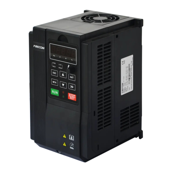
FR500F Series Special Purpose Inverter Chapter 1 Product Information 1.1 Nameplate Information Figure 1-1 Nameplate Information Model Instruction Model numbers on nameplate consist of numbers, symbols, and letters, to express its respective series, suitable power type, power level and other information. -
Page 3: Fr500F Special Purpose Inverter Model Selection
FR500F Series Special Purpose Inverter 1.2 FR500F Special Purpose Inverter Model Selection Table 1-1 FR500F Series Product Model and Technical Data Rated Rated output Applicable motor Model No. Power capacity Input current current 3-Phase:380V,50/60Hz Range:-15%~+30% FR500F-4T-0.7B 0.75 FR500F-4T-1.5B FR500F-4T-2.2B FR500F-4T-4.0B 3.7, 4... -
Page 4: Configuration, Mounting Dimensions And Weight
FR500F Series Special Purpose Inverter 1.3 Configuration, Mounting Dimensions and Weight ◆0.7~2.2KW Dimensions and wall mounting dimensions: Fig 1-3 0.7~2.2kW Wall installation diagram ◆4~22KW Dimensions and wall mounting dimensions: Fig 1-4 4~22kW Wall installation diagram ◆ 30~450kW Dimensions and wall mounting dimensions: ~... - Page 5 FR500F Series Special Purpose Inverter Table 1-2 Configuration, mounting dimensions and weight External and installation dimensions(mm) Weight Mounting Model NO. (Kg) Hole Diameter 3-Phase:380V,50/60Hz Range:-15%~+30% FR500F-4T-0.7B 1.25 FR500F-4T-1.5B FR500F-4T-2.2B 116. FR500F-4T-4.0B 106.6 186.6 176.6 FR500F-4T-5.5B FR500F-4T-7.5B FR500F-4T-011B FR500F-4T-015B FR500F-4T-018B FR500F-4T-022B FR500F-4T-030B 11.8...
-
Page 6: Product Terminals Configuration
FR500F Series Special Purpose Inverter 1.4 Product Terminals Configuration 1.4.1Main Circuit Terminals ◆0.7~2.2KW Main Circuit Terminals Fig.1-6 0.7~2.2kW Schematic of main circuit terminals ◆4~5.5KW Main Circuit Terminals T U V (+) (-) POWER Fig.1-7 4~5.5kW Schematic of main circuit terminals ◆7.5~22KW Main Circuit Terminals... - Page 7 FR500F Series Special Purpose Inverter ◆30~37KW Main Circuit Terminals (+) (-) Fig.1-9 30~37kW Schematic of main circuit terminals ◆45~90KW Main Circuit Terminals: (+) (-) Fig.1-10 45~90kW Schematic of main circuit terminals ◆110~132KW , 250~280KW ,315~450KW Main Circuit Terminals: Fig.1-11 110~132KW , 250~280KW ,315~355KW Main Circuit Terminals...
- Page 8 FR500F Series Special Purpose Inverter ◆160~220KW Main Circuit Terminals: Fig.1-11 160~220KW Main Circuit Terminals Main circuit terminal functions Terminal marks Designation and function of terminals. AC power input terminals for connecting to 3-phase R, S, T AC380V power supply. AC output terminals of inverter for connecting to 3-phase U, V, W induction motor.
- Page 9 FR500F Series Special Purpose Inverter 1.4.2 Control circuit terminals 485+ 485- R2A R2B R2C +24V DI7/HI +10V R1A R1B R1C Control circuit terminals diagram Figure 1-14 Control circuit terminals functions Table 1-4 FR500F Terminal Type Name Function Description Marks Provide +10 V power supply to external unit.
- Page 10 FR500F Series Special Purpose Inverter high-speed pulse The maximum output frequency: 100kHz output Normally open R1A-R1C terminal Normally close R1B-R1C Contact driving capacity: terminal Relay AC250V, 3A, COSØ=0.4. Output Normally open DC 30V, 1A R2A-R2C terminal Normally close R2B-R2C terminal...
-
Page 11: Chapter 2 Debugging Guide
Figure 2-2 Spining Inverter External Wirings 2.2 Two Control Modes FR500F series special purpose inverter for textile machine has Three control modes, users can freely choose any mode by parameters setting, and details refer to parameter H00.34. 1. Linear Mode Linear mode can set 16 multi-steps in total, and every step running speed can be set. - Page 12 FR500F Series Special Purpose Inverter when inverter running into any step, timer starts, and running to this step by acce/dece time, after reach the step, inverter continue to run as this step until timing arrived at the time set by...
-
Page 13: Power-Off Memory Function
Figure 2-5 Length mode running diagram 2.3 Power-off Memory Function FR500F series special purpose inverter for textile machine has power-off memory function, details refer to the function code H00.33. When power-off function selection valid, inverter can remember the step running before power-off, and already finished running time during this step, when starts again,... -
Page 14: Chapter 3 List Of Parameter
FR500F Series Special Purpose Inverter Chapter 3 List of Parameter Group F00~F17 are standard function parameters. Group U00 is status monitoring parameters. Group U01 is fault record parameters. The symbols in the function code table are described as follows: "△ " means the value of this parameter can be modified in stop and running status of drive;... -
Page 15: Five Led (Digital) Display Indicators
FR500F Series Special Purpose Inverter 3.1 Five LED (digital) display indicators Ten thousand’s Unit’s place place Thousand’s place Hundred’s place Ten’s place Fig.3-1 LED indicators 3.2 Standard Function Parameters Table 3-1 Standard Function Parameters Param. Parameter Name Setting Range Default... - Page 16 FR500F Series Special Purpose Inverter 2: Editable via RS485 0: Voltage/Frequency (V/F) control F00.08 Motor 1 control mode × 1:Sensor-less vector control 1 2: Sensor-less vector control 2 0: Digital input terminal 7 F00.09 DI7/HI input mode × 1: Pulse input...
- Page 17 FR500F Series Special Purpose Inverter defined F00.24 Dealer password 0~65535 × F00.25 Setting operation time × 0~65535h(0: Invaild) Group F00: Frequency Command 0: Master frequency source 1: Auxiliary frequency source 2: Master +Auxiliary Frequency source 3: Master - Auxiliary F01.00 ×...
- Page 18 FR500F Series Special Purpose Inverter Frequency compensation F01.14 0.00~50.00Hz 0.00Hz △ per 50Hz Group F02: Start/Stop Control 0: Keypad control (LED off) 1: Terminal control (LED on) F02.00 Run command × 2: Communication control (LED blinking) 0: Forward △ F02.01...
- Page 19 FR500F Series Special Purpose Inverter 2: Enabled at running 3: Enabled at deceleration Dynamic Brake F02.18 128.0% × 90.0~150.0% Voltage F02.19 Brake use ratio 5.0~100.0% 100.0% × 0:No voltage output F02.20 0Hz output selection × 1:Voltage output Auto-start of power-on 0: Invalid F02.21...
- Page 20 FR500F Series Special Purpose Inverter key) adjustment clear 13: Multi-step frequency terminal 1 14: Multi-step frequency terminal 2 15: Multi-step frequency terminal 3 16: Multi-step frequency terminal 4 17: Accel/Decel time determinant 1 18: Accel/Decel time determinant 1 19: Accel/Decel disabled(ramp...
- Page 21 FR500F Series Special Purpose Inverter control 1: Holding Ten’s place: action on power loss 0: Clear 1: Holding Hundreds place: integral function 0: No integral function 1: Integral function enabled Terminal UP/DOWN 1.00Hz/ F04.17 frequency change step △ 0.00~50.00Hz 0.00:Disabled...
- Page 22 FR500F Series Special Purpose Inverter △ F05.06 R1 output delay time 0.0~6000.0s 0.0s F05.07 R2 output delay time 0.0s △ 0.0~6000.0s Unit's place: Y1 0: Positive logic 1: Negative logic Ten’s place: Y2 (same as unit's Enabled state of digital F05.08...
- Page 23 FR500F Series Special Purpose Inverter Set value corresponding △ F06.09 to minimum input of -100.0~100.0% 0.0% curve AI2 Input of inflection point Minimum input of curve AI1~Input F06.10 25.0% △ 1 of curve AI2 of inflection point 2 of curve AI2 Set value corresponding F06.11...
- Page 24 FR500F Series Special Purpose Inverter Set value corresponding to F06.33 0.0% △ -100.0~100.0% minimum input of curve HI Minimum input of curve HI~ △ F06.34 Maximum input of curve HI 50.00kHz 100.00kHz Set value corresponding to F06.35 100.0% △ -100.0~100.0% maximum input of curve HI F06.36...
- Page 25 FR500F Series Special Purpose Inverter Rotor resistance R2 of Model F08.09 × 0.001~65.535Ω async motor 1 defined Leakage inductance L1 Model F08.10 0.01~655.35mH × of async motor 1 defined Mutual inductance L2 of Model F08.11 0.1~6553.5mH × asynchronous motor 1...
- Page 26 FR500F Series Special Purpose Inverter △ F09.13 Excitation boost gain 0.0~200.0% 100.0% Model F09.14 Oscillation Suppression △ 0.0~300.0% defined 0: Digital setting (F09.16) 1:keypad potentiometer 2:AI1 3: Multi-reference Voltage source for V/F F09.15 × separation 4: Pulse setting ( DI7/HI )
- Page 27 FR500F Series Special Purpose Inverter value under torque control Reverse speed limited F10.19 50.00Hz △ 0.00~ Fmax value under torque contro F10.20 Set torque accel time 0.0s △ 0.0~6000.0s △ F10.21 Set torque decel time 0.0~6000.0s 0.0s Static friction torque F10.22...
- Page 28 FR500F Series Special Purpose Inverter overload(Err11)(Same as unit's place ) External equipment fault(Err13) 0: Fault reported and coast to stop 1: Stop according to the stop mode 2: Fault reported but continue to Ten's place: EEPROM read/write fault (Err15) (Same as unit's place) F11.11...
- Page 29 FR500F Series Special Purpose Inverter F11.19 Overload alarm threshold 20.0~200.0% 130.0% × Overload alarm F11.20 activated time that 0.1~60.0s 5.0s × exceeding threshold Inverter overheat warning Model F11.21 × 50~overheat Temperature threshold defined Detection level of power F11.22 5.0~100.0% 20.0% ×...
- Page 30 FR500F Series Special Purpose Inverter △ F12.08 Reference 8 -100.0~100.0% 0.0% F12.09 Reference 9 0.0% △ -100.0~100.0% F12.10 Reference 10 0.0% △ -100.0~100.0% F12.11 Reference 11 0.0% △ -100.0~100.0% △ F12.12 Reference 12 -100.0~100.0% 0.0% △ F12.13 Reference 13 -100.0~100.0% 0.0%...
- Page 31 FR500F Series Special Purpose Inverter Acceleration/deceleration △ F12.34 time of simple PLC 0~3 reference 0 Acceleration/deceleration △ F12.35 time of simple PLC 0~3 reference 1 Acceleration/deceleration F12.36 time of simple PLC △ 0~3 reference 2 Acceleration/deceleration F12.37 time of simple PLC △...
- Page 32 FR500F Series Special Purpose Inverter Group F13 Process PID 0: F13.01 digital setting 1: keypad potentiometer 2: AI1 3: Communication F13.00 PID setting × 4: Multi-Reference 5: DI7/HI pulse input 6: AI2 7: AI3 △ F13.01 PID digital setting 0.0~100.0% 50.0%...
- Page 33 FR500F Series Special Purpose Inverter Holding time of PID F13.21 0.0s × 0.0~6000.0s initial value PID output frequency lower limit~ PID output frequency F13.22 100.0%(100.0% corresponds to 100.0% × upper limit maximum frequency ) PID output frequency –100.0%~PID output frequency F13.23...
- Page 34 FR500F Series Special Purpose Inverter Rising Time of Swing F14.03 5.0s △ 0.0~6000.0s frequency Dropping Time of Swing F14.04 0.0~6000.0s 5.0s △ frequency F14.05 Set length 0m~65535m 1000m × Number of pulses per F14.06 100.0 × 0.1~6553.5 meter Unit’s place: stop when the length...
- Page 35 FR500F Series Special Purpose Inverter 3: No check, data format(1-8-N-1) for RTU F15.02 Local address × 1~247 0: Broadcast address F15.03 Communication timeout 0.0~60.0s 0.0s × F15.04 Response time delay 0~200ms × 0:The inverter is the slave Master-slave F15.05 ×...
- Page 36 FR500F Series Special Purpose Inverter User-defined Display F17.00 00.03 △ 00.00~49.99 Parameter 0 User-defined Display F17.01 00.00~49.99 01.01 △ Parameter 1 User-defined Display △ F17.02 00.00~49.99 01.02 Parameter 2 User-defined Display F17.03 01.08 △ 00.00~49.99 Parameter 3 User-defined Display △...
- Page 37 FR500F Series Special Purpose Inverter Parameter 28 User-defined Display F17.29 00.00 △ 00.00~49.99 Parameter 29 Group U00 Status Monitoring U00.00 Running frequency 0.00~Fup 0.00Hz ⊙ U00.01 Set frequency 0.00~Fmax 0.00Hz ⊙ U00.02 Output voltage 0~660V 0.0V ⊙ U00.03 Output current 0.0A...
- Page 38 FR500F Series Special Purpose Inverter Err02:Decel overcurrent Err03:Constant-speed overcurrent Err04:Accel overvoltage Err05:Decel overvoltage Err06:Constant-speed overvoltage Err07:Bus undervoltage Err08:Short circuit Err09:Power input phase loss Err10:Power output phase loss Err11:Motor overload Err12:Inverter overload Err13:External equipment fault Err14:Module overheat Err15:EEPROM read/write fault Err16:Motor auto-tuning cancelled...
- Page 39 FR500F Series Special Purpose Inverter when previous fault occurred Before-previous fault U01.10 Same as U01.00 ⊙ code Running frequency U01.11 when before-previous 0.00~Fup 0.00Hz ⊙ fault occurred Output current when U01.12 before-previous fault 0.0A 0.0~3000.0A ⊙ occurred Bus voltage when U01.13...
- Page 40 FR500F Series Special Purpose Inverter 400DH H00.13 Multi-steps 12 0.00~600.00Hz 0.00Hz △ 400EH H00.14 Multi-steps 13 0.00Hz 0.00~600.00Hz △ 400FH H00.15 Multi-steps 14 0.00Hz 0.00~600.00Hz △ 4010H H00.16 Multi-steps 15 0.00Hz 0.00~600.00Hz △ Simple PLC 0 step 4011H H00.17 0.0~6000.0s/min/m 0.0s/min/m...
-
Page 41: H00 Textile-Specific Function Group Explaination
FR500F Series Special Purpose Inverter Hundred’s place: power-off memory selection 0: power-off no memory 1: power-off memory Thousand’s place: Simple PLC running time 0:s (second) 1:min (minute) Ten thousand’s place: Length unit 0:0.1m 1:1m 0: Linear mode 4022H H00.34 Running Mode 1: Gradual mode ×... - Page 42 FR500F Series Special Purpose Inverter H00.12 Multi-steps 11 0.00~600.00Hz 0.00Hz △ H00.13 Multi-steps 12 0.00Hz 0.00~600.00Hz △ H00.14 Multi-steps 13 0.00Hz 0.00~600.00Hz △ H00.15 Multi-steps 14 0.00Hz 0.00~600.00Hz △ H00.16 Multi-steps 15 0.00~600.00Hz 0.00Hz △ Simple PLC 0 step 0.0s/min/ H00.17...
- Page 43 FR500F Series Special Purpose Inverter Hundred’s place: Power-off memory selection 0: power-off no memory 1: power-off memory Thousand’s place: Simple PLC running time 0:s (second) 1:min (minute) Ten thousand’s place: Length unit 0:0.1m 1:1m Unit’s place: simple PLC running mode selection...
- Page 44 FR500F Series Special Purpose Inverter Output Frequency(Hz) 50Hz Fault Power down T3.2 T3.1 T3=T3.1+T3.2 Figure 3-1 Power-off Meomory Function Thousand’s place: Simple PLC running time 0:s (second) 1:min(minute) Set unit of simple PLC running time. Ten thousand’s place: Set length unit 0: 0.1m...
- Page 45 FR500F Series Special Purpose Inverter consuming time is set time. When PLC running finished, inverter stops according to the dece time, running diagram as below: Output Frequency(Hz) 50Hz T3 T4 T5 T6 T8 T9 Figure 3-3 Gradual mode running diagram...
- Page 46 FR500F Series Special Purpose Inverter Average rev =Average speed Hz*H00.35 0:Calculated based on Roller speed measurement speed × H00.39 1:Calculated based on pulse input(DI7) H00.40 Roller diameter 0.0~6000.0mm 50.0mm △ H00.41 Roller per revolution 0~100 △ H00.42 Current line speed 0.0~6000.0m/min...
-
Page 47: Chapter 4 Maintenance And Troubleshooting
FR500F Series Special Purpose Inverter Chapter 4 Maintenance and Troubleshooting FR500F series inverter provide a number of warning information and protection, when a fault occurs, the protective function actions, the inverter will stop output, inverter fault relay contact actions, and the inverter displays fault code on its display panel. Before asking for service, user can do the self-examination tips according to this section, analyze fault reason, and find solutions. - Page 48 FR500F Series Special Purpose Inverter 4: The braking unit and braking braking resistor. resistor are not installed. 1: Adjust the voltage to normal Constant-s 1: The input voltage is too high range. Err06 peed 2: An external force drives the...
- Page 49 FR500F Series Special Purpose Inverter small power class. power class. External 1: External fault signal is input Err13 Input fault Reset running via DI. protection 1: The ambient temperature is too high. 1: Lower the ambient 2: The air filter is blocked.
- Page 50 FR500F Series Special Purpose Inverter Check that the load is Load The AC drive running current is Err25 disconnected or the setting becoming 0 lower than F11.22 F11-22 and F11-23 is correct. 1: The load is too heavy or 1: Reduce the load and check...
Need help?
Do you have a question about the FR500F Series and is the answer not in the manual?
Questions and answers
hi, how do I select that the drive must use a command from the plc to start and stop. And on what parameters do I set for this function to work
To configure the Frecon FR500F Series drive to start and stop using a command from the PLC, set the following parameters:
1. Command Source: Set the main command source to PLC.
- Parameter: F01.02
- Value: 5 (PLC)
2. Frequency Source: Set the main frequency source to PLC if frequency control is also from PLC.
- Parameter: F01.03
- Value: 5 (PLC)
This configuration allows the drive to receive both start/stop commands and frequency references from the PLC.
This answer is automatically generated