Table of Contents
Advertisement
Thank you for choosing FRECON developed and produced FR500A&FR510A series
vector control inverter.
FR500A&FR510A series vector control inverter is mainly positioned as a high-end market for
OEM customers and the specific requirements of fan and pump load applications,its flexible design,
both embedded SVC and VF control in one, can be widely used for speed control accuracy, torque
response speed, low-frequency output characteristics and other situations with higher requirements.
This user manual supplies a detailed description of FR500A &FR510A series vector control
inverter includes product characterization, structural features, parameter setting, operation and
commissioning, inspection maintenance and other contents. Be sure to carefully read through the
safety precautions before use, and use this product on the premise that personnel and equipment
safety is ensured.
◆To illustrate the details of the products,pictures in this manual based on products with outer
casing or safety cover being removed. When using this product, please be sure to well install
outer casing or covering by the rules, and operating in accordance with the manual contents.
◆The illustrations this manual for illustration only and may vary with different products you have
ordered.
◆The company is committed to continuous improvement of products, product features will
continue to upgrade, the information provided is subject to change without notice.
◆If you are using have questions, please contact our regional agents or our customer service
center. Customer Service Tel 0755 -33067999.
◆The company's other products please visit our website.
FR500A&FR510A Series Vector Control Inverter
Preface
IMPORTANT NOTES
http://www.frecon.com.cn
- 1 -
Advertisement
Table of Contents

Related Manuals for Frecon FR500A Series


Summary of Contents for Frecon FR500A Series
- Page 1 FR500A&FR510A Series Vector Control Inverter Preface Thank you for choosing FRECON developed and produced FR500A&FR510A series vector control inverter. FR500A&FR510A series vector control inverter is mainly positioned as a high-end market for OEM customers and the specific requirements of fan and pump load applications,its flexible design, both embedded SVC and VF control in one, can be widely used for speed control accuracy, torque response speed, low-frequency output characteristics and other situations with higher requirements.
-
Page 2: Table Of Contents
FR500A&FR510A Series Vector Control Inverter Contents PREFACE................................- 1 - CONTENTS................................- 2 - CHAPTER 1 SAFETY PRECAUTIONS......................- 4 - 1.1 S ..........................- 4 - AFETY ONSIDERATIONS 1.2 P .............................. - 6 - RECAUTIONS CHAPTER 2 PRODUCT INFORMATION....................... - 8 - 2.1 N ..........................- 8 - AMEPLATE INFORMATION... - Page 3 FR500A&FR510A Series Vector Control Inverter F10 V 1..............- 115 - ROUP ECTOR ONTROL ARAMETERS OF OTOR F11 P ....................- 118 - ROUP ROTECTION ARAMETERS F12 M PLC F ............... - 123 - ROUP ULTI EFERENCE AND IMPLE UNCTION F13 P PID..........................- 127 - ROUP ROCESS...
-
Page 4: Chapter 1 Safety Precautions
Users are requested to read this chapter carefully when installing, commissioning and repairing this product and perform the operation according to safety precautions as set forth in this chapter without fail. FRECON will bear no responsibility for any injury and loss as a result of any violation operation. - Page 5 R1A, R1B, R1C andR2A, R2B, R2C. Failure to comply may result in equipment damage. ◆Since all adjustable frequency AC drives from FRECON have been subjected to hi-pot test before delivery, users are prohibited from implementing such a test on this equipment.
-
Page 6: Precautions
1.2.11 Altitude De-rating In places where the altitude is above 1000 m and the cooling effect reduces due to thin air, it is necessary to de-rate the AC drive. Contact FRECON for technical support. 1.2.12 some special usages If wiring that is not described in this manual such as common DC bus is applied, contact the agent or FRECON for technical support. - Page 7 FR500A&FR510A Series Vector Control Inverter easily. The standard parameters of the adaptable motor have been configured inside the AC drive. It is still necessary to perform motor auto-tuning or modify the default values based on actual conditions. Otherwise, the running result and protection performance will be affected. The AC drive may alarm or even be damaged when short-circuit exists on cables or inside the motor.
-
Page 8: Chapter 2 Product Information
FR500A&FR510A Series Vector Control Inverter Chapter 2 Product Information 2.1 Nameplate information Fig.2-1 Nameplate information Model Explanation Model show on product nameplate contains information below. Fig.2-2 Model Explanation - 8 -... -
Page 9: Information Of Product Model
FR500A&FR510A Series Vector Control Inverter 2.2 Information of Product Model Table 2-1 FR500A Product model and technical data Rated Rated output Applicable motor Model No. Power capacity Input current current 3-Phase:380V,50/60Hz Range:-15%~+30% FR500-4T-0.7G/1.5PB 0.75 FR500-4T-1.5G/2.2PB FR500-4T-2.2GB FR500-4T-2.2G/4.0PB FR500-4T-4.0G 3.7, 4 FR500A-4T-4.0G/5.5PB 3.7, 4 FR500A-4T-5.5G/7.5PB... -
Page 10: Technical Features
FR500A&FR510A Series Vector Control Inverter 2.3 Technical Features Table 2-2 Technical features Project Specifications Rated input 3-phase 380 V (-15%~+30%) voltage (V) Rated input Power input See table 2-1 current (A) Rated input 50Hz/60Hz,tolerance±5% frequency (Hz) Applicable See table 2-1 motor(kW) Rated output See table 2-1... - Page 11 FR500A&FR510A Series Vector Control Inverter system Automatic voltage When the grid voltage changes, can automatically maintain adjustment a constant output voltage (AVR) Fast current limit Minimize over current fault protection inverter running function Over voltage System automatically limits of current and voltage during Over current operation to prevent frequent Command...
-
Page 12: Parts Drawing
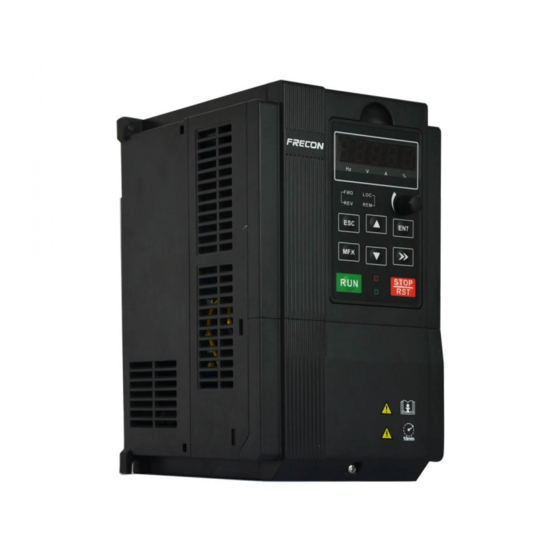
FR500A&FR510A Series Vector Control Inverter Ambient -10℃~40℃ temperature Relative 5~95%, no condensation humidity Vibration Less than 5.9m/s2 (0.6g) Storage -20℃~+70℃ temperature Efficiency Rated power≥93% Installation Wall-mounted or Flange mounting Others IP grade IP20 Cooling Fan cooled method 2.4 Parts Drawing ◆0.7~2.2kW Outline: Fan cover Upper case... -
Page 13: Configuration, Mounting Dimensions And Weight
FR500A&FR510A Series Vector Control Inverter ◆30~450kW Outline: Fan cover Keypad Chassis Nameplate Fig 2-5 30~450Kw Outline 2.5 Configuration, Mounting Dimensions and Weight ◆0.7~2.2KW Dimensions and wall mounting dimensions: Fig 2-6 0.7~2.2kW Wall installation diagram - 13 -... - Page 14 FR500A&FR510A Series Vector Control Inverter ◆4~22KW Dimensions and wall mounting dimensions: Fig 2-7 4~22kW Wall installation diagram ◆ 30~450kW Dimensions and wall mounting dimensions: Fig 2-8 30 450KW Wall installation diagram ~ Table 2-3 Configuration, mounting dimensions and weight External and installation dimensions(mm) Weight Mounting Model NO.
-
Page 15: Flange Mounting Dimensions
FR500A&FR510A Series Vector Control Inverter FR500A-4T-7.5GB FR500A-4T-7.5G/011PB FR500A-4T-011G/015PB FR500A-4T-015G/018PB FR500A-4T-018G/022PB FR500A-4T-022G/030PB FR500A-4T-030G/037PB 11.8 FR500A-4T-037GB FR500A-4T-037G/045P FR500A-4T-045G/055P FR500A-4T-055G/075P FR500A-4T-075G/090P FR500A-4T-090G/110P FR500A-4T-110G/132P 11.5 FR500A-4T-132G/160P FR500A-4T-160G/185P 11.5 FR500A-4T-185G/200P FR500A-4T-200G/220P FR500A-4T-220G/250P FR500A-4T-250G/280P 924.5 FR500A-4T-280G/315P FR500A-4T-315G/355P FR500A-4T-355G/400P FR500A-4T-400G/450P 1025. 988.5 FR500A-4T-450G *Note:The model of FR510A series inverter only needs to replace FR500A in the above table with FR510A 2.6 Flange mounting dimensions ◆: 4~225kW Flange mounting dimensions... -
Page 16: External Dimensions Of Keypad
FR500A&FR510A Series Vector Control Inverter dimensions Flange mounting ◆:30~90kW Fig 2-10 30~90kW Flange mounting Table 2-4 Flange mounting dimensions table External and installation dimensions(mm) Model.NO 3-Phase:380V,50/60Hz Range:-15%~+30% FR510A-4T-2.2G/4.0PB FR510A-4T-4.0G/5.5PB FR510A-4T-5.5G/7.5PB FR510A-4T-7.5GB FR510A-4T-7.5G/011PB FR510A-4T-011G/015PB FR510A-4T-015G/018PB FR510A-4T-018G/022PB FR510A-4T-022G/030PB FR510A-4T-055G/075P(B) FR510A-4T-075G/090P(B) 11.5 FR510A-4T-090G/110P(B) *Note:The model of FR510A series inverter only needs to replace FR500A in the above table with FR510A 2.7 External Dimensions of Keypad... - Page 17 FR500A&FR510A Series Vector Control Inverter 15.5 74.6 71.6 15.3 Fig 2-12- 7.5~450KW Keyboard size diagram External keyboard installation instruction: 1. first install the panel according to inverter’s power range corresponding to the size of hole as shown on scheme 2-12, 2.
-
Page 18: Chapter 3 Installation And Wiring
FR500A&FR510A Series Vector Control Inverter Chapter 3 Installation and Wiring 3.1 Installation Environment 1) Ambient temperature in the range of -10℃~50℃. 2) Drive should be installed on surface of flame retardant object, with adequate surrounding space for heat dissipation. 3) Installation should be performed where vibration is less than 5.9m/s2 (0.6g). 4) Avoid from moisture and direct sunlight. - Page 19 FR500A&FR510A Series Vector Control Inverter 3.2.1 Single installation Ventilation clearance Ventilation clearance Fig.3-2 Single inverter mounting orientation and space requirements 3.2.2 Multiple installations a. Multiple parallel installations Fig.3-3 multiple inverters installed direction and space requirements Air Outlet Direction Baffle - 19 -...
-
Page 20: Fixed Manner
FR500A&FR510A Series Vector Control Inverter Fig.3-4 Multiple inverters installed Upper and lower mounting direction and space Table 3-1 Requirement of minimum mounting clearances Mounting clearances (mm) Drive model 4~22kW ≥50 ≥100 3.3 Fixed manner a. Wall installation Wall mounting dimensions refer to Chapter II(table 2-3),As shown in Fig drilling four holes in the mounting surface,Put the inverter against the panel and mate 4 holes, and then tighten screws in the 4 holes tighten any of the 2 screws in diagonal position, tighten 4 holes with screws for strengthened installation. -
Page 21: Remove & Mount Keypad And Cover
FR500A&FR510A Series Vector Control Inverter Do not take the sunken screws as shown in the picture. Otherwise, inverter may be damaged Take screws combined with springs and plain gaskets to Install inverter. 3.4 Remove & Mount Keypad and Cover a. Remove keypad: Disassemble keypad. See following Figure: Push the buckle on the keypad in Direction 1 first, and then lift up the keypad in Direction 2. - Page 22 FR500A&FR510A Series Vector Control Inverter Fig.3-7(c) External remote operation control panel d. Disassembly of Terminal Cover: loosen the captive cover screws as shown in Fig.3-7(d),then remove terminal cover in the direction as shown in the Figure below. Screw Fig.3-7(d) Open cover e.
- Page 23 FR500A&FR510A Series Vector Control Inverter Screw Fig.3-7(e) Mount covers f. Removing and installing the cover method as shown in fig 3-7(f) :First, loosen the screws Then open the cover up. According to the assembly when the shell shown method to be assembled in place, and then tighten the screws.
-
Page 24: Dust Cover Installation And Removal(Optional Accessories
FR500A&FR510A Series Vector Control Inverter 3.5 Dust cover installation and removal(Optional accessories) a. Install dust cover: The dust cover shown in Fig3-8 parallel to the housing assembly(No cock around is installed). b. Removing dust cover: cording to the dust cover arrow direction, at one end of the dust cover and hard to lift the dust cover under the desirable. - Page 25 FR500A&FR510A Series Vector Control Inverter Table 3-2 Instructions of peripheral devices Picture Device Instructions Cable Transmitting electrical signals. Purpose: disconnect power supply and protect the equipments in case of abnormal overcorrect occurs Type selection: breaking current of circuit breaker is Circuit defined to be 1.5~2 times the rated current of the breaker...
- Page 26 FR500A&FR510A Series Vector Control Inverter FR500A-4T-037GB FR500A-4T-037G/045P(B) FR500A-4T-045G/055P(B) FR500A-4T-055G/075P(B) FR500A-4T-075G/090P(B) FR500A-4T-090G/110P(B) FR500A-4T-110G/132P FR500A-4T-132G/160P FR500A -4T-185G/200P FR500A -4T-200G/220P 150*2 FR500A -4T-220G/250P 150*2 FR500A -4T-250G/280P 185*2 95*2 FR500A -4T-280G/315P 185*2 95*2 FR500A -4T-315G/355P 150*3 75*3 FR500A -4T-355G/400P 150*4 75*4 FR500A -4T-400G/450P 1000 1000 150*4 75*4...
- Page 27 FR500A&FR510A Series Vector Control Inverter 160kw ACL-4T-160 External optional OCL-4T-160 185kw ACL-4T-185 External optional OCL-4T-185 200kw ACL-4T-200 External optional OCL-4T-200 220kw ACL-4T-220 External optional OCL-4T-220 250kw ACL-4T-250 External optional OCL-4T-250 280kw ACL-4T-280 External optional OCL-4T-280 315kw ACL-4T-315 External optional OCL-4T-315 355kw ACL-4T-355 External optional...
-
Page 28: Wiring Way
FR500A&FR510A Series Vector Control Inverter Note: 1. Can meet EMI C2 after installing input filter. 2. Input and output filter are external and optional. 3.7 Wiring way Fig.3-10 FR510A Inverter wiring diagram Remarks: ○ 1)◎refers to main circuit terminals., refers to control circuit terminals. 2)User selects braking resistor based on real needs,Please refer to the braking resistor Selection Guide. -
Page 29: Terminal Configuration
FR500A&FR510A Series Vector Control Inverter 3.8 Terminal Configuration 3.8.1 Main Circuit Terminals ◆0.7~2.2KW Main Circuit Terminals Fig.3-11 0.7~2.2kW Schematic of main circuit terminals ◆4~5.5KW Main Circuit Terminals T U V (+) (-) POWER Fig.3-12 4~5.5kW Schematic of main circuit terminals ◆7.5~22KW Main Circuit Terminals (+) (-) Fig.3-13 7.5~22kW Schematic of main circuit terminals... - Page 30 FR500A&FR510A Series Vector Control Inverter ◆30~37KW Main Circuit Terminals (+) (-) Fig.3-14 30~37kW Schematic of main circuit terminals ◆45~90KW Main Circuit Terminals: (+) (-) Fig.3-15 45~90kW Schematic of main circuit terminals ◆110~132KW , 250~280KW ,315~450KW Main Circuit Terminals: Fig.3-16 110~132KW , 250~280KW ,315~450KW Main Circuit Terminals - 30 -...
- Page 31 FR500A&FR510A Series Vector Control Inverter ◆160~220KW Main Circuit Terminals: Fig.3-16 160~220KW Main Circuit Terminals Main circuit terminal functions Terminal marks Designation and function of terminals. AC power input terminals for connecting to 3-phase R, S, T AC380V power supply. AC output terminals of inverter for connecting to 3-phase U, V, W induction motor.
- Page 32 FR500A&FR510A Series Vector Control Inverter 3.8.2 Control circuit terminals 485+ 485- R2A R2B R2C +24V R1A R1B R1C DI7/HI +10V Fig.3-17 Control circuit terminals Table 3-7 Description of control circuit terminals Type Terminal Name Function Description Provide +10 V power supply to external unit.
- Page 33 FR500A&FR510A Series Vector Control Inverter Analog output AO1, AO2 on the control board AO2-GND terminal 2 Impedance requirements≥10kΩ Voltage range:0~24V Open collector Y1-COM output 1 Current range:0~50mA Open collector Besides features of Y1, it can be used Switch output output 2 OR for High-speed pulse output channels.
- Page 34 FR500A&FR510A Series Vector Control Inverter recommended to avoid drive faults as a result of noise. Operating instructions for switching value input terminal ◆A: Dry contact (a) Internal power supply (b)External power supply Fig.3-18 Dry contact ATTENTION: When external power supply is used, the jumper between +24V and PLC must be removed. Otherwise, it may result in equipment damage.
- Page 35 FR500A&FR510A Series Vector Control Inverter (a) Internal power supply (b)External power supply Fig.3-20 internal power supply open collector PNP connection 3)Instructions of digital output terminal (a) Internal power supply (b)External power supply Fig.3-21 wiring when Y2 and HO output with pull-up resistors ATTENTION: When set to be pulse output, Y2/HO terminal shall output 0~100kHz pulse signal.
- Page 36 FR500A&FR510A Series Vector Control Inverter absorbing circuit such as RC absorbing circuit (note that its leakage current shall be less than holding current of controlled contactor or relay), piezoresistor or fly-wheel diode etc. shall be mounted (be sure to pay close attention to polarity in case of DC electromagnetic circuit). Absorbing devices should be mounted close to the ends of relay or contactor.
-
Page 37: Emi Solutions
FR500A&FR510A Series Vector Control Inverter ≥30KW RFI jumper method: Screw matter is jumped state, release is not jumped state After jumped Before jumped Fig.3-24 30kW above RFI jumper schematic ATTENTION: 1. When power is applied to the AC motor drive, do not cut off the RFI jumper. 2. - Page 38 FR500A&FR510A Series Vector Control Inverter Signal lines must orthogonally cross power lines if this cross inevitable. Motor cables shall be placed in thick protective screen like more than 2mm-thick pipelines or buried cement groove, also, power lines can be put into metallic conduit and grounded well with shielded cables.
-
Page 39: Chapter 4 Operation And Display
FR500A&FR510A Series Vector Control Inverter Chapter 4 Operation and display 4.1 Introduction of Keypad As a human-machine interface, you can modify the parameters, monitor the working status and start or stop the inverter by operating the keypad. Its appearance and function area as shown in the following figure: Fig.4-1 Keypad 4.1.1 Key and potentiometer Functions on keypad... - Page 40 FR500A&FR510A Series Vector Control Inverter 4.1.2 Keypad Indicators There are 8 Indicators on the keypad, whose descriptions are as shown in Table 4-2. Table 4-2 Description of indicators Indicator Name Meaning ON: currently displayed parameter is Frequency frequency Voltage ON: currently displayed parameter is voltage Unit Current ON: currently displayed parameter is current...
-
Page 41: Viewing And Modifying Function Codes
FR500A&FR510A Series Vector Control Inverter Table 4-4 Prompt characters Prompt symbol Meaning Prompt symbol Meaning Motor parameter Err00~Err99 Fault type TUNE identification in process A00~A99 Alarm type -END- Write parameter 4.2 Viewing and Modifying Function Codes The keypad of the FR500A&FR510A adopts three-level menu. The three-level menu consists of function code group (Level I), function code (Level II), and function code setting value (level III), as shown in the figure 4-2. -
Page 42: Motor Auto-Tuning
FR500A&FR510A Series Vector Control Inverter 4.4 Motor Auto-tuning Tuning is valid only when the keyboard command mode. Set tuning mode (stationary or rotating), press the ENT key to confirm, the keyboard will display TUNE, then press the RUN key, the inverter will drive motor acceleration and deceleration, positive inversion operation,and the run indicator lights. -
Page 43: Chapter 5 List Of Parameter
FR500A&FR510A Series Vector Control Inverter Chapter 5 List of Parameter Group F00~F17 are standard function parameters. Group U00 is status monitoring parameters. Group U01 is fault record parameters. The symbols in the function code table are described as follows: "△ " means the value of this parameter can be modified in stop and running status of drive; "×"... -
Page 44: Five Led (Digital) Display Indicators
FR500A&FR510A Series Vector Control Inverter 5.1 Five LED (digital) display indicators Fig.5-1 LED indicators 5.2 Standard Function Parameters Table 5-1 Standard Function Parameters Param. Parameter Name Setting Range Default Attr Group F00: System Parameters F00.00 Setting of User Password 0~65535 ×... - Page 45 FR500A&FR510A Series Vector Control Inverter 0: V/F control 1:Sensor-less vector control 1 2: Sensor-less vector control 2 3. Vector control with PG card 0: Digital input terminal 7 F00.09 DI7/HI input mode × 1: Pulse input Unit's place: AI1 0: Analog input 1: Digital input F00.10 AI1\AI2\AI3 input mode...
- Page 46 FR500A&FR510A Series Vector Control Inverter Group F01: Frequency Command 0: Master frequency source 1: Auxiliary frequency source 2: Master +Auxiliary Frequency source 3: Master - Auxiliary F01.00 × selection 4: MAX{Master, Auxiliary } 5: MIN {Master, Auxiliary } 6: AI1 ( Master + Auxiliary ) 7: AI2 ( Master +Auxiliary ) 0:Master digital setting (F01.02) 1: keypad potentiometer...
- Page 47 FR500A&FR510A Series Vector Control Inverter 1: Terminal control (LED on) 2: Communication control (LED △ blinking) 0: Forward F02.01 Running direction 1: Reverse 0: Reverse enabled F02.02 Reverse-proof action × 1: Reverse disabled Dead time between F02.03 0.0~6000.0s 0.0s × forward and reverse Unit’s place: Start Mode 0:Start directly...
- Page 48 FR500A&FR510A Series Vector Control Inverter braking F02.19 Brake use ratio 5.0~100.0% 100.0% × 0: No voltage output F02.20 0Hz output selection × △ 1: Voltage output Auto-start of power-on 0: Invalid F02.21 again 1: Valid △ Waiting time between F02.22 auto-start and power-on 0.0~10.0s 0.5s...
- Page 49 FR500A&FR510A Series Vector Control Inverter 13: Multi-step frequency terminal 1 14: Multi-step frequency terminal 2 15: Multi-step frequency terminal 3 16: Multi-step frequency terminal 4 17: Accel/Decel time determinant 1 18: Accel/Decel time determinant 2 19: Accel/Decel disabled(ramp stop not inclusive) 20: Switch to auxiliary speed setting 21: PLC status reset 22: Simple PLC paused...
- Page 50 FR500A&FR510A Series Vector Control Inverter output encoder (FR510A only) △ Filtering time of digital F04.10 0.000~1.000s 0.010s input terminal △ Delay time before F04.11 terminal 0.0~300.0s 0.0s DI1 is valid △ Delay time before F04.12 terminal 0.0~300.0s 0.0s DI2 is valid DI5, DI4, DI3, DI2, DI1 0: Positive logic(Terminals are on at Terminal DI1~DI5...
- Page 51 FR500A&FR510A Series Vector Control Inverter F05.00 Y1 output function 00: No output × 01: Drive is running F05.01 Y2 output function 02: Fault output F05.02 Relay 1 output function × 03: Frequency-level detection FDT1 output 04: Frequency-level detection FDT2 output 05: Drive in 0Hz running 1(no output at stop) 06: Drive in 0Hz running 2(output at...
- Page 52 FR500A&FR510A Series Vector Control Inverter F05.13 FDT2 lower bound 0.00~Fmax 30.00Hz × Consecutive running F05.14 0.0~6000.0Min 0.0:Disabled 0.0Min × time Accumulative power-on F05.15 0~65535h 0:Disabled × time setting Accumulative running F05.16 0~65535h 0:Disabled × time setting 0: Disabled F05.17 Brake control selection ×...
- Page 53 FR500A&FR510A Series Vector Control Inverter AI2~100.0% △ Set value corresponding F06.15 to maximum input of -100.0~100.0% 100.0% △ curve AI2 Minimum input of curve 0.0%~input of inflection point1 F06.16 0.0% of curve AI3 △ Set value corresponding F06.17 to minimum input of -100.0~100.0% -100.0% △...
- Page 54 FR500A&FR510A Series Vector Control Inverter 02: Command frequency 03: Output current 04: Output voltage 05: Output power 06: Bus voltage 07: +10V 08: keypad potentiometer Y2/HO output function F07.02 09: AI1 × (when used as HO) 10: AI2 11: AI3 12: HI 13: Output torque 14: Ao communication given 1...
- Page 55 FR500A&FR510A Series Vector Control Inverter async motor 1 defined Field weakening coeff 1 F08.13 0.0~100.0 × of async motor 1 Field weakening coeff 2 F08.14 0.0~100.0 × of async motor 1 Field weakening coeff 3 F08.15 0.0~100.0 × of async motor 1 PMSM stator resistance Model F08.16...
- Page 56 FR500A&FR510A Series Vector Control Inverter △ boost) Cut-off frequency of F09.02 0.00~Fmax 50.00Hz △ torque boost Multi-point V/F frequency F09.03 0.00~F09.05 0.00Hz △ 1(F1) Multi-point V/F voltage 1 F09.04 0.0~100.0 5.0% △ (V1) Multi-point V/F frequency F09.05 F09.03~F09.05 5.00Hz △ 2(F2) Multi-point V/F voltage 2 F09.06...
- Page 57 FR500A&FR510A Series Vector Control Inverter will be maintained after accelerating. (FR510A only) Group F10 Vector Control Parameters of Motor 1 0: speed control F10.00 Speed/torque control × △ 1: torque control ASR low-speed F10.01 0.0~100.0 15.0 △ proportional gain Kp1 ASR low-speed F10.02 0.001~30.000s...
- Page 58 FR500A&FR510A Series Vector Control Inverter 0: Optimization method 1 SVC optimization F10.25 1: Optimization method 2 × method 2: Optimization method 3 0: Set by F10.18 & F10.19 1: Keypad potentiometer Max Frequency source 2: AI1 F10.26 × under torque control 3: AI2 4: AI3 5: Pulse setting ( DI7/HI )
- Page 59 FR500A&FR510A Series Vector Control Inverter Unit's place: Bus undervoltage 0: Fault reported and coast to stop 1: Stop according to the stop mode 2: Fault reported but continue to 3: Fault protection disabled Ten's place: Power input phase Loss (Err09) F11.10 Protection action 1 03330...
- Page 60 FR500A&FR510A Series Vector Control Inverter Ten's place: compared object 0: Rated current of motor 1: Rated current of drive Hundred’s place: Fault reported 0:No fault reported 1:Fault reported Thousand’s place: whether to decelerate or not when overload alarm 0: No deceleration 1: Deceleration Ten thousand's place: given mode for overload threshold...
- Page 61 FR500A&FR510A Series Vector Control Inverter Zero drift value of motor F11.36 -100~100℃ △ temperature sensor △ F11.37 Reserved Motor temperature F11.38 0~200℃ 90℃ warning action threshold △ Motor temperature F11.39 protection action 0~200℃ 110℃ threshold Unit’s place: Overspeed Action Selection 0:Report error and coast to stop 1:Warning and ramp to stop 2: Alarm and continue run with...
- Page 62 FR500A&FR510A Series Vector Control Inverter 5: AI2 6: AI3 Unit's place: PLC running mode 0: Stop after a single cycle 1: Continue to run with the last frequency after a single cycle 2: Repeat cycles Ten’s place: started mode 0: Continue to run from the step of stop (or fault) 1: Run from the first step “multi-step frequency 0”...
- Page 63 FR500A&FR510A Series Vector Control Inverter △ Acceleration/deceleratio F12.39 n time of simple PLC 0~3 reference 5 △ Acceleration/deceleratio F12.40 n time of simple PLC 0~3 reference 6 △ Acceleration/deceleratio F12.41 n time of simple PLC 0~3 reference 7 △ Acceleration/deceleratio F12.42 n time of simple PLC 0~3...
- Page 64 FR500A&FR510A Series Vector Control Inverter 4: AI1-AI2 5: Max{AI1,AI2} 6: Min{AI1,AI2} 7: DI7/HI pulse input △ 8: AI3 PID setting feedback F13.03 0.0~6000.0 100.0 range 0: Forward action F13.04 PID action direction × △ 1: Reverse action Filtering time of PID F13.05 0.000~10.000s 0.000s...
- Page 65 FR500A&FR510A Series Vector Control Inverter Unit’s place: PID operation selection when stop 0:Do not operate when stop 1:Operate when stop Ten’s place: output is limited by output frequency 0:No limited 1:limited Hundred’s place: UP/DOWN digital given of PID F13.26 PID operation selection 00000 ×...
- Page 66 FR500A&FR510A Series Vector Control Inverter 0: Not stop 1: Stop Ten’s place: length calculation method 0: pulse by pulse 1: Reference maximum frequency 2: Refer to Ai1 channel 3: Refer to AI2 channel 4: Refer to AI3 channel F14.08 Set count value 1000 ×...
- Page 67 FR500A&FR510A Series Vector Control Inverter Communication 1: Current running frequency Sending Data 0: No return Message return when F15.07 communication error 1: Return △ 0: Positive and negative F15.08 U group return value 1: Absolute value Group F16 Keys and Display of Keypad Parameters 0: No function 1: Jog F16.00...
- Page 68 FR500A&FR510A Series Vector Control Inverter △ LED displayed F16.10 parameters setting 4 on 0~99(correspond U00.00~U00.99) △ stop status △ F16.11 Speed display coefficient 0.00~100.00 1.00 F16.12 Power display coefficient 0.0~300.0% 100.0% △ The enable difference F16.13 range of U00.00 and 0.00Hz~5.00Hz 0.10Hz U00.01...
- Page 69 FR500A&FR510A Series Vector Control Inverter △ User-defined Display F17.24 00.00~49.99 13.02 △ Parameter 24 User-defined Display F17.25 00.00~49.99 13.08 △ Parameter 25 User-defined Display F17.26 00.00~49.99 13.09 △ Parameter 26 User-defined Display F17.27 00.00~49.99 00.00 △ Parameter 27 User-defined Display F17.28 00.00~49.99 00.00...
- Page 70 FR500A&FR510A Series Vector Control Inverter Find encoder origin at 0: Not find F18.22 × beginning (FR510A only) 1: Find Encoder line number F18.23 0~10000 1024 × (FR510A only) 0: ABZ encoder 1: UVW encoder Encoder type F18.24 2: Rotary encoder ×...
- Page 71 FR500A&FR510A Series Vector Control Inverter △ V/F slip compensation F19.11 0.0~300.0% 80.0% △ gain Stator voltagedrop △ F19.12 0.0~200.0% 100.0% compensation gain △ F19.13 Excitation boost gain 0.0~200.0% 100.0% F19.14 Oscillation Suppression 0.0~300.0% 100.0% 0: Digital setting (F19.16) 1: keypad potentiometer 2: AI1 3: Multi-reference Voltage source for V/F...
- Page 72 △ FR500A&FR510A Series Vector Control Inverter △ F20.08 ASR output filtering time 0.0~500.0ms 0.0ms F20.09 Vector control slip gain 50~200% 100% Digital setting of torque F20.10 upper limit in speed 80.0~200.0% 165.0% × △ control mode Excitation adjustment F20.11 0.00~10.00 0.50 △...
- Page 73 FR500A&FR510A Series Vector Control Inverter △ only) PMSM Flux weakening F20.32 0.0~200.0% 100.0% limit (FR510A only) PMSM excitation current F20.33 frequency high point F10.34~600.00Hz 15.00Hz △ (FR510A only) PMSM excitation current F20.34 frequency low point 0.0~F10.33 10.00Hz △ (FR510A only) PMSM excitation current F20.35 conversion delay...
- Page 74 FR500A&FR510A Series Vector Control Inverter Direction 1:Reverse Regression Origin F21.15 0.00Hz~600.00Hz 10.00Hz × Frequency 1 Regression Origin △ F21.16 0.00Hz~60.00Hz 1.00Hz × Frequency 2 △ F21.17 Carry amount 0 high 0~9999 △ F21.18 Carry amount 0 low 0~9999 △ F21.19 Carry amount 1 high 0~9999 △...
- Page 75 FR500A&FR510A Series Vector Control Inverter △ VDI5, VDI4, VDI3, VDI2, VDI1 Settings of virtual VDI F22.06 0: Invalid 00000 terminal status 1: Valid △ : Internal short circuited to Function selection of physics DIx F22.07 virtual VDO1 terminals Other: The same as function code output F05.00 △...
- Page 76 FR500A&FR510A Series Vector Control Inverter terminal U00.15 AI1 input 0.0~100.0% 0.0% ⊙ U00.16 AI2 input 0.0~100.0% 0.0% ⊙ U00.17 AI3 input -100.0~100.0% 0.0% ⊙ Keypad potentiometer U00.18 0.0~100.0% 0.0% ⊙ input U00.19 HI input 0.00~100.00kHz 0.00kHz ⊙ U00.20 AO1 output 0.0~100.0% 0.0% ⊙...
- Page 77 FR500A&FR510A Series Vector Control Inverter Err11: Motor overload Err12: Inverter overload Err13: External equipment fault Err14: Module overheat Err15: EEPROM read/write fault Err16: Motor auto-tuning cancelled Err17: Motor auto-tuning fault Err18: Communication overtime Error Err19: PID feedback loss Err20: Continuous running time Reached Err21: Parameter upload fault Err22: Parameter download fault...
- Page 78 FR500A&FR510A Series Vector Control Inverter Bus voltage when U01.13 before-previous fault 0~1200V ⊙ occurred Cumulative running time U01.14 when before-previous 0~65535h ⊙ fault occurred Previous 3 categories of U01.15 The same with U01.00 Err00 ⊙ faults Previous 4 categories of U01.16 The same with U01.00 Err00...
-
Page 79: Chapter 6 Specification Of Parameters
FR500A&FR510A Series Vector Control Inverter Chapter 6 Specification of Parameters Group F00 System Parameters F00.00 Setting of user password Range: 0~65535 Default: 0 Setting of password: A number greater than 100 could be set as a user password by entering this password into F00.00 and pressing ENT key to confirm once, the password setting will take effect as long as there is no operation on keypad within 2 minutes, or cutting the power off and power up again . - Page 80 FR500A&FR510A Series Vector Control Inverter F00.08 Motor 1 control mode Range:0~2 Default:1 Unit’s place: Motor 1 control mode 0: V/f control Constant voltage&frequency ratio control. Applicable to such cases in which the performance Requirement to the drive is not rigorous, or using one drive to drive several motors, or it is difficult to identify motor parameters correctly, etc.
- Page 81 FR500A&FR510A Series Vector Control Inverter defined At lower carrier frequency, output current of the drive produces higher harmonics, motor loss increases, and temperature and motor noise rise, but drive temperature, drive leakage current, and drive interference to external devices are lower or less. With higher carrier frequency, drive temperature will rise, drive leakage current is bigger, and drive interference to external devices is bigger.
-
Page 82: Group F01 Frequency Command
FR500A&FR510A Series Vector Control Inverter defined The parameters are only for reference and cannot be edited. F00.24 Dealer password Range: 0~65535 Default: 0 Range: 0~65535h(0: F00.25 Setting operation time Default: 0 Invaild) When total running time ≥F00.25, inverter will not work. When setting F00.24, need to unlock F00.24 dealer passport, after time setting, need to input dealer passport to lock. - Page 83 FR500A&FR510A Series Vector Control Inverter as Fig. 6-2: Fig. 6-2 If 10V power supply inside the drive is used with potentiometer, the connection diagram is shown as Fig. 6-3. Note that the toggle switch should be switched to voltage input side. Fig.
- Page 84 FR500A&FR510A Series Vector Control Inverter Master frequency command is determined by analog input AI2. 9: AI3 Master frequency command is determined by analog input AI3. Digital setting of master F01.02 Range:0.00~FmaxHz Default:50.00Hz frequency When master frequency source selection F01.01 is set to 1, this parameter value will be the initial value of master frequency command.
-
Page 85: Group F02 Start/Stop Control Start/Stop Control
FR500A&FR510A Series Vector Control Inverter shall not work in low frequency for a long time. Otherwise, motor service lifespan will be shortened due to overheating. 2. Correlation of Fmax, Fup and Fdown: 0.00Hz ≤Fdown ≤Fup≤Fmax ≤600.00Hz Operation when command F01.11 frequency lower than lower Range:0~1 Default: 0... - Page 86 FR500A&FR510A Series Vector Control Inverter Dead time of forward and F02.03 Range:0.0~6000.0s Default:0.0s reverse The dead time with 0Hz output during the transition from forward to reverse, or from reverse to forward. As shown in Fig. 6-4. Fig. 6-4 F02.04 Start mode Default: 000 Range:00000~31111...
- Page 87 FR500A&FR510A Series Vector Control Inverter Tracking direction is negative direction 3: Starting direction Track from start direction F02.05 Start frequency Default:0.00Hz Range:0.00~10.00Hz F02.06 Startup frequency holding time Range:0.0~100.0s Default:0.0s To ensure the motor torque at AC drive startup, set a proper startup frequency. In addition, to build excitation when the motor starts up, the startup frequency must be held for a certain period.
- Page 88 FR500A&FR510A Series Vector Control Inverter Waiting time of stop DC braking: When the running frequency decreases to the initial frequency of stop DC braking, the AC drive stops output for a certain period and then starts DC braking. This prevents faults such as over current caused due to DC braking at high speed.
-
Page 89: Group F03 Accel/Decel Parameters
FR500A&FR510A Series Vector Control Inverter Auto-start of power on again: 0:Invalid,after power off and power on again, inverter can’t run before receiving running command。 When running on keyboard control or RS485 communication control, inverter will automatically clear running commands when power off。 When running on external terminal control , when power-off and then power on , no matter what value the function code F02.21 set, control commands of external terminal(FWD/REV)... - Page 90 FR500A&FR510A Series Vector Control Inverter The 1 section and the last section in accelerating or decelerating are in smooth transition. The acceleration/deceleration curve is similar to S curve. When it is in S curve, the final acceleration/deceleration time= S curve time+ Linear acceleration/deceleration time. See Figure 6-13 for 2 acceleration/deceleration modes.
-
Page 91: Group F04 Digital Input
FR500A&FR510A Series Vector Control Inverter Figure 6-7 Group F04 Digital Input F04.00 Function of terminal DI1 Range:0~99 Default:1 F04.01 Function of terminal DI2 Range:0~99 Default:2 F04.02 Function of terminal DI3 Range:0~99 Default:7 F04.03 Function of terminal DI4 Range:0~99 Default:13 F04.04 Function of terminal DI5 Range:0~99 Default:0... - Page 92 FR500A&FR510A Series Vector Control Inverter If the frequency source is master frequency source setting, the UP and DOWN terminals used to clear the modification by using the setting UP/DOWN function or the increment/decrement key on the clear (terminal, keypad, returning the set frequency to the value of master keypad) frequency source setting.
- Page 93 FR500A&FR510A Series Vector Control Inverter switched to keypad terminal status is switched from OFF to ON, run command will control be switched to keypad control. Run command This terminal should be enabled by trigger edge. When this switched to terminal terminal status is switched from OFF to ON, run command will control be switched to terminal control.
- Page 94 FR500A&FR510A Series Vector Control Inverter It is only valid in simple carry control mode. FWD carry REV carry It is only valid in simple carry control mode. Carry amount selection terminal 1 When in simple carry mode, through a combination of the 3 Carry amount terminals of different states, most can choose 8 kinds of carry selection terminal 2...
- Page 95 FR500A&FR510A Series Vector Control Inverter Reference 0 F12.16 Reference 1 F12.01 Reference 2 F12.02 Reference 3 F12.03 Reference 4 F12.04 Reference 5 F12.05 Reference 6 F12.06 Reference 7 F12.07 Reference 8 F12.08 Reference 9 F12.09 Reference F12.10 Reference F12.11 Reference F12.12 Reference F12.13...
- Page 96 FR500A&FR510A Series Vector Control Inverter DI1 is valid Delay time before terminal F04.12 Range:0.0~300.0s Default:0.0s DI2 is valid Delay time before terminal F04.19 Range:0.0~300.0s Default:0.0s DI1 is invalid Delay time before terminal F04.20 Range:0.0~300.0s Default:0.0s DI2 is invalid The four parameters set the delayed response time before DI1/DI2 is valid or invalid ATTENTION: Terminal delay time F04.11and F04.12 can be set with filtering time F04.10 at the same time.
- Page 97 FR500A&FR510A Series Vector Control Inverter RUN command Stop Reverse RUN Forward RUN Stop Figure 6-8 setting of two-line mode 1 As shown in the preceding figure, when only K1 is ON, the AC drive instructs forward rotation. When only K2 is ON, the AC drive instructs reverse rotation. When K1 and K2 are ON & OFF simultaneously, the AC drives stops.
- Page 98 FR500A&FR510A Series Vector Control Inverter As shown in the preceding figure, if SB1 is ON, the AC drive instructs forward rotation when SB2 is pressed to be ON and instructs reverse rotation when SB3 is pressed to be ON. The AC drives stops immediately after SB1 becomes OFF.
- Page 99 FR500A&FR510A Series Vector Control Inverter ↑ ↑ Operation Stop command ↑ ↑ Operation Stop command Figure 6-12 Pulse operation stop control diagram Press SB1, inverter forward operation, press SB1 again inverter stop; Press SB2, inverter reverse operation, press SB2 again, inverter stop. Press the SB1 button inverter run clockwise, press the SB1 button to stop the SB2 button is pressed again converter;...
-
Page 100: Group F05 Digital Output
FR500A&FR510A Series Vector Control Inverter 1: Edge trigger + Electrical level effective(When power on) When terminal is given running command, the terminal is detected to jump from OFF to ON and maintain ON, inverter start to run. 2: Edge trigger + Electrical level effective(Every start) When terminal is given running command, the terminal is detected to jump from OFF to ON and maintain ON, inverter start to run. - Page 101 FR500A&FR510A Series Vector Control Inverter Set count value The terminal becomes ON when the count value reaches attained the value set in F14.07. The terminal becomes ON when the count value reaches Designated count the value set in F14.08. Refer to the specification of value attained parameter F14.07 and F14.08.
- Page 102 FR500A&FR510A Series Vector Control Inverter Fig. 6-12 Detection width of F05.09 Range:0.0~20.0Hz Default:5.0Hz frequency attained This parameter should be set with digital output terminal "frequency attained". When the difference between output frequency and command frequency is less than this value, terminal "frequency attained"...
- Page 103 FR500A&FR510A Series Vector Control Inverter Fig. 6-14 F05.14 Consecutive running time Default: 0.0Min Range:0.0~6000.0Min This parameter should be set with digital output terminal “Consecutive running time attained". When current running time attains the value of F05.14, corresponding terminal outputs ON. Current running time is cleared when stop.
-
Page 104: Group F06 Analog And Pulse Input
FR500A&FR510A Series Vector Control Inverter Fig 6-15 Break control logic scheme 1)After inverter receives a run command, accelerate the run to set F05.18 brake open frequency. 2)After the frequency reaches F05.18 set frequency, inverter keeps constant running and the duration reaches the F05.20 set brake open waiting time, inverter running constant speed continue to the F05.20 set brake open waiting time, switching output “brake output”... - Page 105 FR500A&FR510A Series Vector Control Inverter Set value corresponding F06.05 to input of inflection Range:-100.0~100.0% Default: 100.0% point 2 of curve AI1 Range: Input of inflection point Maximum input of curve F06.06 Default:100.0% 2 of curve AI1~100.0% Set value corresponding to F06.07 Range:-100.0~100.0% Default:100.0%...
- Page 106 FR500A&FR510A Series Vector Control Inverter Figure 6-16 (1) Figure 6-17 (2) Range:0.0%~input of F06.08 Minimum input of curve AI2 Default:1.0% inflection point1 of curve AI2 Set value corresponding to F06.09 Range:-100.0~100.0% Default:0.0% minimum input of curve AI2 Range:Minimum input of Input of inflection point F06.10 curve AI2~Input of inflection...
- Page 107 FR500A&FR510A Series Vector Control Inverter Range:Input of inflection F06.22 Maximum input of curve AI3 Default:100.0% point 2 of curve AI3~100.0% Set value corresponding to F06.23 Range:-100.0~100.0% Default:100.0% maximum input of curve AI3 Curve AI2 is defined by F06.08~F06.15. Curve AI3 is defined by F06.16~F06.23. The usage of curve AI2 and curve AI3 is the same as that of curve AI1.
-
Page 108: Group F07 Analog And Pulse Output
FR500A&FR510A Series Vector Control Inverter ATTENTION: When pulse input is selected as the frequency command, DI7/HI terminal shall be set to "pulse input" function (F00.09 is set to 1). F06.36 HI terminal filtering time Range:0.000~10.000s Default:0.100s F06.36 defines the filtering time of pulse input terminals DI7/HI. Long filtering time results in strong immunity from interference but slow response, while short filtering time brings rapid response but weak immunity from interference. -
Page 109: Group F08 Parameters Of Motor 1
FR500A&FR510A Series Vector Control Inverter Define output filtering time of AO1 terminal. F07.06 AO2 offset Range:-100.0~100.0% Default:0.0% F07.07 AO1 gain Range:-2.000~2.000 Default:1.000 F07.08 AO2 filtering time Default:0.000s Range:0.000~10.000s Adjustment method of AO2 output curve is the same as AO1. HO maximum output F07.09 Range:0.01~100.00kHz Default:50.00kHz... - Page 110 FR500A&FR510A Series Vector Control Inverter The parameters in F08.08 to F08.15 are asynchronous motor parameters. These parameters are unavailable on the motor nameplate and are obtained by means of motor auto-tuning. Only F08.08 to F08.10 can be obtained through static motor auto-tuning. Through complete motor auto-tuning, encoder phase sequence and current loop PI can be obtained besides the parameters in F08.08 to F08.12.Each time "Rated motor power"...
-
Page 111: Group F09 V/ F Control Parameters Of Motor 1
FR500A&FR510A Series Vector Control Inverter 0.0:Invalid Speed feedback F08.26 0.0s disconnection detection time 0.1~10.0s It is effective with PG vector control mode. The detection time of PG disconnection is set in seconds. When the converter runs at non-zero speed, if the input signals of A and B phases of the encoder are not detected continuously within the time set by F08.26, the "Err36"... - Page 112 FR500A&FR510A Series Vector Control Inverter motor, the output voltage would be rated voltage of motor. What is different is this pattern can set 4 inflection points by F09.03~F09.10. 2: 1.2nd power 3: 1.4nd power 4: 1.6nd power 5: 1.8nd power 6: 2.0nd power Parameter values 2~6 apply to torque-dropped loads such as fans and water pumps.
- Page 113 FR500A&FR510A Series Vector Control Inverter Cut-off frequency of torque boost: F09.02 specifies the frequency under which torque boost is valid. Torque boost becomes invalid when this frequency is exceeded, as shown in the following figure. Fig. 6-25 F09.03 Multi-point V/F frequency 1(F1) Range:0.0~F09.05 Default:0.0Hz F09.04...
- Page 114 FR500A&FR510A Series Vector Control Inverter may cause overheat or even burnt out of the motor and overcurrent stall or overcurrent protection of the AC drive. F09.11 V/F slip compensation gain Range:0.0~300.0% Default: 80.0% This parameter is valid only for the asynchronous motor. It can compensate the rotational speed slip of the asynchronous motor when the load of the motor increases, stabilizing the motor speed in case of load change.
-
Page 115: Group F10 Vector Control Parameters Of Motor 1
FR500A&FR510A Series Vector Control Inverter It is used to correct the torque when reversing. PMSM acceleration current F09.22 Range:0.0~200.0% Default:0.0% compensation setting Compensation current drop F09.23 time after PMSM Range:0.0~100.0s Default:2.0s acceleration Maintain ID current value F09.24 Range:0.0~200.0% Default:0.0% after PMSM acceleration It is used for the current compensation parameter during acceleration under VF control mode of PMSM. - Page 116 FR500A&FR510A Series Vector Control Inverter increase the proportional gain and reduce the integral time. Be aware that this may lead to system oscillation. The recommended adjustment method is as follows: If the factory setting cannot meet the requirements, make proper adjustment. Increase the proportional gain first to ensure that the system does not oscillate, and then reduce the integral time to ensure that the system has quick response and small overshoot.
- Page 117 FR500A&FR510A Series Vector Control Inverter The target torque is set by means of communication. Forward speed limited value F10.18 Range:0.0~Fmax Default:50.0Hz under torque control Reverse speed limited value F10.19 Range:0.0~Fmax Default:50.0Hz under torque control When F00.26=0,Two parameters are used to set the maximum frequency in forward or reverse rotation in torque control mode.
-
Page 118: Group F11 Protection Parameters
FR500A&FR510A Series Vector Control Inverter synchronous motor Flux weakening integral(Ti) of F10.31 0.00~60.00s Default: 0.5s synchronous motor Flux weakening limit of F10.32 0.0~200.0% Default: 100.0% synchronous motor F10.30~F10.31 is the PI parameter used for weak magnetic regulation, and F10.32 is used to limit the PI output of weak magnetic regulation. - Page 119 FR500A&FR510A Series Vector Control Inverter Current limit mode 2 is applied to the applications which are sensitive to acceleration/ deceleration time. In this mode, the motor current is automatically adjusted by regulating the output frequency as per the PI parameters set in F11.03 and F11.04. For load with larger inertia if overcurrent occurs during acceleration, the proportional gain may be increased.
- Page 120 FR500A&FR510A Series Vector Control Inverter If "Stop according to the stop mode" is selected, the AC drive displays A** and stops according to the stop mode. After stop, the AC drive displays Err**. If "Continue to run" is selected, the AC drive continues to run and displays A**. The running frequency is set in F11-14.
- Page 121 FR500A&FR510A Series Vector Control Inverter Unit's place: detection option 0: Always detect Overload alarm works all the time during drive running. 1: Detect at constant speed only Overload pre-alarm only works during constant-speed running of inverter. Ten’s place: compared object 0: Rated current of motor Compared object is the rated current relative to motor, and display "...
- Page 122 FR500A&FR510A Series Vector Control Inverter Instantaneous power off Range: 60.0%~F11.31 F11.30 Default: 80.0% bus voltage Instantaneous power off Range: F11.30~100.0% F11.31 Default: 85.0% recovery voltage Instantaneous power off Range: 0.01~10.00s F11.32 Default: 0.10s voltage judge time Instantaneous power off Range: 0.1~100.0% F11.33 Default: 40.0% gain Kp...
-
Page 123: Group F12 Multi-Reference And Simple Plc Function
FR500A&FR510A Series Vector Control Inverter Unit’s place: Overspeed Action Selection 0:Report error and coast to stop 1:Warning and ramp to stop 2: Alarm and continue run with failure frequency 3:No protection Ten’s place: Selection of Excessive Speed Deviation(same as Unit’s place) F11.41 Overspeed detection value Default : 120.0%... - Page 124 FR500A&FR510A Series Vector Control Inverter 1: keypad potentiometer 2: AI1 3: Process PID output 4: X7/HI pulse input 5: AI2 6: AI3 It determines the setting channel of reference 0. You can perform convenient switchover between the setting channels. When multi-reference or simple PLC is used as frequency source, the switchover between two frequency sources can be realized easily.
- Page 125 FR500A&FR510A Series Vector Control Inverter PLC automatically starts another cycle after finishing one until there is a stop command, shown as Fig. 6-24. Fig. 6-32 Ten’s place: started mode 0: Continue to run from the step of stop (or fault) At the moment drive stop, the drive automatically records the running time of current step.
- Page 126 FR500A&FR510A Series Vector Control Inverter Default:0.0s(h) F12.31 Running time of step 13 Range:0.0~6000.0s(h) Default:0.0s(h) F12.32 Running time of step 14 Range:0.0~6000.0s(h) Default:0.0s(h) F12.33 Running time of step 15 Range:0.0~6000.0s(h) Acceleration/deceleration time F12.34 Range: 0~3 Default: 0 of simple PLC reference 0 Acceleration/deceleration time F12.35 Range: 0~3...
-
Page 127: Group F13 Process Pid
FR500A&FR510A Series Vector Control Inverter Group F13 Process PID The purpose of process PID control is to make feedback value consistent with the set value. PID control diagram is as shown in Fig. 6-25. Fig. 6-33 F13.00 PID setting Range: 0~7 Default: 0 Select the setting source of PID control. - Page 128 FR500A&FR510A Series Vector Control Inverter Negative Negative Positive Positive adjustment: When feedback signal is smaller than PID setting, output frequency of the drive will rise to reach PID balance. When feedback signal is bigger than PID setting, output frequency of the drive will drop to reach PID balance.
- Page 129 FR500A&FR510A Series Vector Control Inverter bigger than the set value of F13.15, PID adjustment is determined by Kp2, Ti2 and Td2 set at F13.11 to F13.13. 2: Switched by terminal When digital input terminal "PID parameters switch" is OFF, it is determined by Kp1, Ti1 and Td1. When "PID parameters switch"...
-
Page 130: Group F14 Swing Frequency, Fixed Length, Count And Wakeup
FR500A&FR510A Series Vector Control Inverter 1: limit When using PID regulation, Setting “1”can prevent output lags caused by the existence of acceleration and deceleration. Hundred’s place: Action selection when using UP/DOWN function to modify the frequency in PID mode. 0:Zero clearing when power off. Clear the value(increased or decreased) caused by UP/DOWN function when power off 1:Keep the value when power off. - Page 131 FR500A&FR510A Series Vector Control Inverter Swing frequency setting F14.00 Range:0~1 Default:0 mode This parameter is used to select the base value of the swing amplitude. 0: Relative to the central frequency (group F01) It is variable swing amplitude system. The swing amplitude varies with the central frequency (set frequency).
- Page 132 FR500A&FR510A Series Vector Control Inverter Command when the length F14.07 Range:00~12 Default: 0 attained Units place: stop when the length reaches 0: not stop 1: stop. When the actual length detected reaches the length set in f14.05, select whether to stop. The actual length can be cleared through the terminal of "length reset"...
-
Page 133: Group F15 Communication Parameters
FR500A&FR510A Series Vector Control Inverter Range: 0.00~Wake up F14.12 Dormancy frequency Default: 0.00Hz frequency F14.13 Dormancy delay time Range: 0.0~6000.0s Default: 0.0s Range: 0.0%~Dormancy F14.17 Wake up pressure Default: 10.0% pressure Range: Wake up F14.18 Dormancy pressure Default: 50.0% pressure~100.0% The parameters are used for the dormancy and wake up function in water supply application During inverter operation, when F14.15 set to be “0”, and when setting frequency is lower than F14.12, after delay time of F14.13, inverter entry dormancy and stop. -
Page 134: Group F16 Keys And Display Of Keypad Parameters
FR500A&FR510A Series Vector Control Inverter 2: Odd Parity check, data format (1-8-O-1) for RTU 3: No check, data format (1-8-N-1) for RTU F15.02 Local address Range:1~247 Default:1 Set this drive address. 0 is broadcast address, while available addresses are 1~247. F15.03 Communication timeout Range:0.0~60.0s... -
Page 135: Group F17 User-Defined Display Parameters
FR500A&FR510A Series Vector Control Inverter LED displayed parameters F16.06 Range:0~99 Default:2 setting 4 on running status Sets LED displayed parameters on running status. When a number of parameters are selected to be displayed, skim- through could be performed using key >> on keypad. 0~99 corresponding U00.00~U00.99. -
Page 136: Group F18 Parameters Of Motor 2
FR500A&FR510A Series Vector Control Inverter User-defined Display F17.16 Range:00.00~49.99 Default:08.02 Parameter 16 User-defined Display F17.17 Range:00.00~49.99 Default:08.03 Parameter 17 User-defined Display F17.18 Range:00.00~49.99 Default:08.04 Parameter 18 User-defined Display F17.19 Range:00.00~49.99 Default:08.05 Parameter 19 User-defined Display F17.20 Range:00.00~49.99 Default:08.30 Parameter 20 User-defined Display F17.21 Range:00.00~49.99... -
Page 137: Group F21 Position Control
FR500A&FR510A Series Vector Control Inverter Group F21 Position Control Position control is only effective in the presence of PG vector control. Position control includes zero servo and spindle orientation control. F21.00 Selection of Position Control Range:0~5 Default:0 Mode 0: Non-position control No position control is performed. - Page 138 FR500A&FR510A Series Vector Control Inverter By inputting the state combination of "Directional Position Selection Terminals 1-2" into the switching quantity, the switching can be carried out among the four orientation positions of the spindle, as described in the table below.。 Orientation Position Orientation Position Selection Orientation position...
- Page 139 FR500A&FR510A Series Vector Control Inverter When the motor is locked in the orientation position, such as changing the setting value of the current orientation position, or switching the orientation position by selecting the terminal through the orientation position, the motor rotates to the new position in the reverse direction. Ten’s place: Do orientation or not when stop inverter If this bit is set to 1, orientation action will be executed when the inverter stops.
- Page 140 FR500A&FR510A Series Vector Control Inverter Following are F21.13~F21.32 for simple carry function description. The simple carry control process is shown in the following figure: Fig.6-31 Regression Origin F21.13 Range:0~1 Default:0 Selection The origin signal is detected by the "origin signal input" terminal through the digital input, and the ON signal is input by the terminal at the origin position, while the OFF signal is input by the terminal when it is not at the origin position.
- Page 141 FR500A&FR510A Series Vector Control Inverter This function sets the direction of rotation when the inverter returns to the origin. F21.13 is valid at 1 time. Regression Origin F21.15 Range:0.00~Fup Default:10.00Hz frequency 1 When the frequency converter starts, if the "origin signal input" terminal signal is OFF, that is, when it is not in the origin position, it runs in accordance with the direction set by F21.14 and the frequency set by F21.15.
- Page 142 FR500A&FR510A Series Vector Control Inverter F21.23 Carry amount 3 high value Range:0~9999 Default:0 F21.24 Carry amount 3 low value Range:0~9999 Default:0 F21.25 Carry amount 4 high value Range:0~9999 Default:0 F21.26 Carry amount 4 low value Range:0~9999 Default:0 F21.27 Carry amount 5 high value Range:0~9999 Default:0 F21.28...
- Page 143 FR500A&FR510A Series Vector Control Inverter eight carry quantities can be selected. Specific relations are as follows: Carry amount Carry amount Carry amount Carry amount selection terminal 3 selection terminal 2 selection terminal 1 Carry amount 0 ( F21.17、 F21.18) Carry amount 1 ( F21.19、 F21.20)...
-
Page 144: Group F22 Virtual Io
FR500A&FR510A Series Vector Control Inverter It is mainly used to adjust the phase between the given and feedback when it is used with the "forward position offset enablement" and "reverse position offset enablement" terminals. When the position is synchronized, if the "positive position offset enable" terminal is valid, the phase of the converter control motor will gradually change along the positive direction;... -
Page 145: Group U00 Status Monitoring
FR500A&FR510A Series Vector Control Inverter Positive and negative logic of VD0 output terminal: Positive logic: If terminal is invalid, then output 0, if terminal is valid, then output 1. Negative logic: If terminal is invalid, then output 1, if terminal is valid, then output 0. Group U00 Status Monitoring Group U00 is used to monitor the AC drive's running state. -
Page 146: Group U01 Fault Record
FR500A&FR510A Series Vector Control Inverter U00.21 AO2 output Range: 0.0~100.0% Default: 0.0% U00.22 HO output Range: 0.00~100.00kHz Default: 0.00kHz U00.23 Temperature of inverter Range:-40.0~120.0℃ Default: 0.0℃ Accumulative power-on U00.24 Range:0~65535min Default: 0min time U00.25 Accumulative running time Range:0~65535min Default: 0min U00.26 Cumulative power-on time Range:0~65535h... - Page 147 FR500A&FR510A Series Vector Control Inverter U01.10 Before-previous fault code Range:0~31 Default:0 Running frequency when U01.11 before-previous fault Range:0.00~Fup Default:0.0Hz occurred Output current U01.12 whenbefore-previous fault Range:0.0~3000.0A Default:0.0A occurred Bus voltage when U01.13 before-previous fault Range:0~1200V Default:0V occurred Cumulative running time U01.14 when before-previous fault Range:0~65535h...
-
Page 148: Chapter 7 Maintenance And Troubleshooting
FR500A&FR510A Series Vector Control Inverter Chapter 7 Maintenance and Troubleshooting FR500A&FR510A inverter provides a number of warning information and protection, when a fault occurs, the protective function is activated, the inverter will stop output, inverter fault relay contact, and in the inverter displays the fault code on the display panel. Before seeking service user can press the self-examination tips in this section, analyze problems, and identify solutions. - Page 149 3: The bus voltage is normal range. abnormal. 3: Contact the agent or 4: The rectifier bridge and Frecon. buffer resistor are faulty. 5: The drive board is faulty. 6: The main control board is faulty. 1: The output circuit is grounded or short circuited.
- Page 150 FR500A&FR510A Series Vector Control Inverter small power class. higher power class. 1: The load is too heavy or 1: Reduce the load and locked-rotor occurs on the check the motor and Err12 Inverter overload motor. mechanical condition. 2: The AC drive model is of too 2: Select an AC drive of small power class.
- Page 151 FR500A&FR510A Series Vector Control Inverter Module temperature The temperature sensor Err24 For technical support detection failure or cable break disconnection Check that the load is The AC drive running current disconnected or the setting Err25 Load becoming 0 is lower than F11.22 F11-22 and F11-23 is correct.
-
Page 152: Chapter 8 Maintenance And Inspection
FR500A&FR510A Series Vector Control Inverter Chapter 8 Maintenance and Inspection 8.1 Inspection Frequency semiconductor devices, passive electronic components, and the movement device is configured, these devices have life, even under normal working conditions, if over the useful life, some devices may have characteristic changes or failure. In order to prevent this phenomenon leads to failure and must be checked daily, periodic inspection, parts replacement and other preventative maintenance checks. -
Page 153: Maintenance
FR500A&FR510A Series Vector Control Inverter connection and noise, fixed loose. replacement of bad parts. Semiconduct ● Are stained with dirt and dust; ● Clean the operating or devices ● Are there significant changes in environment; appearance. ● Replace damaged parts. Electrolytic ●... - Page 154 FR500A&FR510A Series Vector Control Inverter Figure 8-1 (a) Remove the fan covers Figure 8-1 (b) Remove the fan Fan Installation 1.Figure 8-2 (a) shown in finger pressure to the inside of the fan under the lead terminal elastic snaps, while a little harder vertically into the lead terminal, and then fan vertically into the slot. 2.Figure 8-2 (b), (c) as shown in the fan shroud assembly ramp into the hole at one end and the other end to snap into place.
-
Page 155: Appendix A: Modbus Communication Protocol
FR500A&FR510A Series Vector Control Inverter Appendix A: Modbus Communication Protocol 1. Application Scope 1. Applicable series: FRECON FR series inverter. 2. Applicable network: Support Modbus protocol, RTU format, withsingle-master/multi-slave Communication network of RS485 bus. The typical RTU message frame format:... - Page 156 FR500A&FR510A Series Vector Control Inverter 4.3 Allocation of Register Addresses name Description High byte function code group number, F00~F31, U00, U01, respectively, corresponding to the high byte address is 00H~1FH, 30H, 31H. Low byte of the group function code number, from 0 to 99 corresponding to the low byte address is 00H~63H.
- Page 157 FR500A&FR510A Series Vector Control Inverter Torque set point (-3000~3000, 1000 corresponds to 100.0% 2004H motor rated current) Retention 2005~20FF 4.5 The status and function of the read address Description: (read only) Status word address functional status word 0000H: parameter setting 0001H: slave run 0002H: JOG operation 2100H...
- Page 158 FR500A&FR510A Series Vector Control Inverter Register start address 0x0000~0xFFFF The number of register 0x0000~0xFFFF CRC parity Slave responds : Address of slave The local address Command Code 0x06 Register start address 0x0000~0xFFFF The number of register 0x0000~0xFFFF CRC parity Command code 0x08: Circuit Diagnosis and Setting ADU Item Byte No.
- Page 159 FR500A&FR510A Series Vector Control Inverter unsigned int CRC_Cal_Value (unsigned char Data, unsigned char Length) unsigned int crc_value = 0xFFFF; int i = 0; while (Length--) crc_value ^= Data++; for (i=0; i<8; i++) if (crc_value & 0x0001) crc_value = (crc_value>>1) ^ 0xa001; else crc_value = crc_value>>1;...
- Page 160 FR500A&FR510A Series Vector Control Inverter 8. Illustration 1, No. 01 reads the output frequency value (U00.00), returned 5000, that 50.00Hz. To send data: 01 03 30 00 00 01 8B 0A The received data is: 01 03 02 13 88 B5 12 2, No.
-
Page 161: Appendix B: Braking Resistor
FR500A&FR510A Series Vector Control Inverter Appendix B: Braking Resistor When the inverter with high inertia loads or need to slow down rapid deceleration, Motor will in the state of power generation, the energy is transferred to the inverter DC link via the inverter bridge, causing the bus voltage of the inverter rises, when more than a certain value, the inverter will report overvoltage fault, and even lead to inverter power module damage of overvoltage, to prevent this happening, you must configure the brake components. - Page 162 FR500A&FR510A Series Vector Control Inverter Cables listed in above table refer to the lead cable of single resistor. The DC bus should be updated if the resistors are in parallel connection. Cable should withstand voltage above AC450V,and temperature resistance of cable: 105℃. - 162 -...
- Page 163 FR500A&FR510A Series Vector Control Inverter Appendix C: PG Card FR510A series is equipped with PG cards showed as below, as optional parts, is the necessary part for inverter with closed loop vector control mode. PG card feedback the real-time speed of motor through the signal acquisition from encoder to achieve the precise control of motor speed and steering Model Description...
-
Page 164: Abz Encoder
FR500A&FR510A Series Vector Control Inverter Installation diagram shown as below C-1: 1) All kinds of PG cards are installed in the same place 2) Cut off the power when to install PG card or uninstall it. 3) Connecting the 20 PIN interface of PG card to J3 interface of control board. Fig.C-1 PG card installation C.1 ABZ encoder PG card External view:... - Page 165 FR500A&FR510A Series Vector Control Inverter Terminals outline drawing: Fig.C-3(a)EXC-PG01 terminals Fig.C-3(b)EXC-PG02 terminals Table C-2 Terminal function description Model Connection object Interface name Description Encoder output singal A, maximum A+、A- frequency 300kHz The differential Encoder output signal B, maximum B+、B- EXC-PG input incremental frequency 300kHz encoder interface...
- Page 166 FR500A&FR510A Series Vector Control Inverter Fig. C-5 Connection schematic diagram of EXC-PG01 andthe open collector output encoder Fig. C-6 Connection schematic diagram of EXC-PG01 and the push output encoder Usage method 1) Follow Figure C-1 to loading PG card 2) Follow Figure C-4、C-5、C-6 to connect PG card and encoder 3) Shielded cable earthing line PE is connected directly to the fixed screw of PG card 4) According to the actual situation to set the inverter parameters as follow: Parameter setting...
-
Page 167: Rotary Transformer
FR500A&FR510A Series Vector Control Inverter C.2 Rotary transformer PG card Outline and its interface: Fig.C-7 EXC-PG03 Schematic diagram and its DB9 pin interface DB9 PIN Name REF- REF+ COS+ COS- SIN+ Null Null Null SIN- PIN function Model Connecting object Pin name Description COS+、... - Page 168 FR500A&FR510A Series Vector Control Inverter C.3 UVW Encoder PG card There are two types of PG card of UVW encoder: one can only accept signals from encoder (exc-pg04b); the other can accept AB signals from upper computer (exc-pg04) in addition to encoder signals.
-
Page 169: Ecn1313
FR500A&FR510A Series Vector Control Inverter J3 terminal description: J3 terminal is used to receive signals from UVW encoder.。 Terminal Name Description +5V power Encoder differential signal A+ Encoder differential signal A- Encoder differential signal B+ Encoder differential signal B- Encoder differential signal Z+ Encoder differential signal Z- Encoder differential signal U+ Encoder differential signal U-... - Page 170 FR500A&FR510A Series Vector Control Inverter EXC-PG05 ECN1313 Encoder 24V output and its common 24_COM、COM terminal 5V output and its ground 5V_GND、GND A differential signal A+、A- B differential signal B+、B- B signal OC output (24V) A signal OC output (24V) CLK+, CLK- ECN1313 differential clock input DATA+, DATA- ECN1313 differential data input...
-
Page 171: Sin -Cos Encoder Pg Card
FR500A&FR510A Series Vector Control Inverter C.5 Sin-Cos encoder PG card Outline and its interface: Fig.C-9 EXC-PG06 Sin-Cos encoder PG card DB15 PIN: Num. Pin Name Description Differential signal B- Null Differential signal R+ Differential signal R- Differential signal A+ Differential signal A- Power ground Differential signal B+ PG VCC...
Need help?
Do you have a question about the FR500A Series and is the answer not in the manual?
Questions and answers
Good day i want a wiring diagram for my FR500-2S-5.5-h I need to connect input 240v
Wiring kase kare