Frecon PV Series User Manual

Frecon PV Series User Manual

Solar pumping inverter
Table of Contents

Advertisement

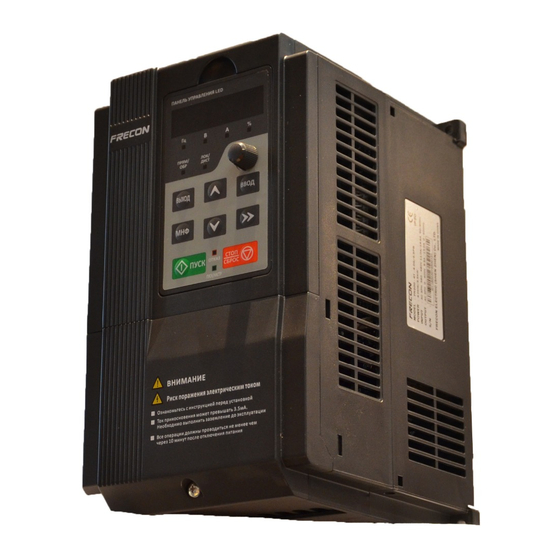
PV200 special inverters are developed for power supply of water pumps, based on the core
control arithmetic of FR200 vector control inverters, combined with the control requirements of PV
water pump application. The function of maximum power tracking, dormant at weak light, wake up at
strong light, high water level dormant, under-load pre-warning and other control protection functions
can ensure normal operation of water pumps according to the customers' requirements to switch to the
grid power supply.
Please refer to this manual to commission the inverter, product maintenance refer to FR200 user
manual.
◆To illustrate the details of the products,pictures in this manual based on products with outer
casing or safety cover being removed. When using this product, please be sure to well install
outer casing or covering by the rules, and operating in accordance with the manual contents.
◆The illustrations in this manual are for illustration only and may vary with different products
you have ordered.
◆The company is committed to continuous improvement of products, product features will
continue to upgrade, the information provided is subject to change without notice.
◆If there is any questions when using, please contact our regional agents or our customer
service center:(+86-0755-33067999)
◆For other products, please visit our website. http://www.frecon.com.cn
Preface
IMPORTANT NOTES
- 1 -
PV series Solar Pumping Inverter

Advertisement

Table of Contents
loading
Need help?

Need help?

Do you have a question about the PV Series and is the answer not in the manual?

Questions and answers

Subscribe to Our Youtube Channel

Summary of Contents for Frecon PV Series

  • Page 1 ◆If there is any questions when using, please contact our regional agents or our customer service center:(+86-0755-33067999) ◆For other products, please visit our website. http://www.frecon.com.cn - 1 -...
  • Page 2 PV series Solar Pumping Inverter - 2 -...
  • Page 3: Table Of Contents

    PV series Solar Pumping Inverter Contents Preface ................................- 1 - Contents ............................... - 3 - Chapter One Product Overview ....................... - 4 - 1.1 Name Plate ............................- 4 - 1.2 Product Specifications ........................- 5 - 1.3 Dimension Drawing .......................... - 8 - Chapter Two Commissioning Guide ....................
  • Page 4: Chapter One Product Overview

    PV series Solar Pumping Inverter Chapter One Product Overview 1.1 Name Plate Figure 1-1 Name Plate Model Instruction Model numbers on name plate consist of numbers, symbols, and letters, to express its respective series, suitable power type, power level and other information.
  • Page 5: Product Specifications

    PV series Solar Pumping Inverter 1.2 Product Specifications 1.2.1 Electric specification of AC220V and DC310V Input product Table 1-1 Electric specification of AC220V and DC310V Input product Recommended Maximum Output Adaptive Size of Model No. Solar Array Input DC Current A...
  • Page 6 PV series Solar Pumping Inverter Input specification PV Input Maximum Input DC 400VDC Voltage Recommended Voc 320~370VDC Range Recommended MPPT 250~350VDC Voltage Range Starting Voltage 120~400VDC Range Grid or backup generator input Input voltage Single phase 220V(-15%~30%) Output specification Rated output voltage...
  • Page 7 PV series Solar Pumping Inverter PV200-4T-7.5B 20.5 PV200-4T-011B P2-3 PV200-4T-015B PV200-4T-018B 38.5 18.5 PV200-4T-022B 46.5 P2-4 PV200-4T-030B PV200-4T-037 P2-5 PV200-4T-045 PV200-4T-055 P2-6 PV200-4T-075 PV200-4T-090 PV200-4T-110 P2-7 PV200-4T-132 PV200-4T-160 PV200-4T-185 P2-8 PV200-4T-200 Input specification PV Input Maximum Input DC 800VDC Voltage Recommended Voc 500~700VDC...
  • Page 8: Dimension Drawing

    PV series Solar Pumping Inverter Protection Lighting Protection, over-current, overvoltage, output phase-lose, Built-in Protection under-load, under-voltage, short circuit, overheating, water pump run dry etc. General Parameters No direct sunshine, no dust、 corrosive gas、 combustible gas、 oil mist、 Application Site steam、dripping or salinity etc.
  • Page 9 PV series Solar Pumping Inverter Dimensions and installation size(mm) Model No. P1-1 151.5 110.8 121.8 140.5 P1-2 1.3.2 PV200 a: 0.75~15kW Dimensions and wall mounting dimensions ~ Figure 1-3 0.75 15kW Wall Installation Diagram b: 18.5~200kW Dimensions and installation dimensions ~...
  • Page 10 PV series Solar Pumping Inverter Table 1-4 Wall Mounting Size Table Dimensions and installation size(mm) Weight Model No. Installation (Kg) Aperture P2-1 106.6 176.6 P2-2 P2-3 P2-4 15.5 P2-5 27.5 P2-6 P2-7 829.5 77.7 1107 1078 138.5 P2-8 - 10 -...
  • Page 11: Chapter Two Commissioning Guide

    PV series Solar Pumping Inverter Chapter Two Commissioning Guide 2.1 PV Panel Power Supply Commissioning 1. Wiring drawings of below inverters shown as Figure 2-1: PV100 series, PV200 series 3 phase 220V inverters with power lower than 15kw and 3 phase 380V inverters with power lower than 30kw.
  • Page 12 PV series Solar Pumping Inverter PV panels U/T1 R/L1 V/T2 S/L2 PV200 Note: if it is connected to the power or W/T3 T/L3 generator, the terminal short films Short film between R/S/T must be removed, or will cause the fires, and even...
  • Page 13: Grid Or Generator Power Supply Wirings

    PV series Solar Pumping Inverter 6. Setting of fault point and fault delay reset time If clients need to use the pre-warning of weak light, water-logged, under-load, failure monitoring point, delay time and reset time, water-logged/controlled function can be set as H00.15~H00.19 on demand;...
  • Page 14 PV series Solar Pumping Inverter PV panels Note:KM1 and KM2 is a pair of U/T1 R/L1 interlocking V/T2 contactors S/L2 PV200 W/T3 T/L3 Grid or generator set +24V Short film +24V RUN/STOP Operation panel PV Voltage Y2/HO Given selection DI7/HI...
  • Page 15: Wiring Diagram Between Vfd And Single Phase Motor

    PV series Solar Pumping Inverter 2.3 Wiring diagram between VFD and single phase motor 2.3.1 Single phase motor introduction Single phase motor generally means asynchronous single phase motor powered by single phase AC 220V, there’re two phase winding in motor stator and motor rotor is common squirrel cage. The...
  • Page 16 PV series Solar Pumping Inverter Running capacitor Centrifugal Starting switch capacitor Secondary Main winding winding 220VAC Figure 2-8 Internal wiring of motor with double capacitors Resistor starting mode single phase motor, and internal wiring is as below: Centrifugal switch Secondary...
  • Page 17 PV series Solar Pumping Inverter 220VAC Secondary Main winding winding PV100 Figure 2-11 Forward wiring between PV100 VFD and motor Motor reverse can’t be completed through parameter setting of inverter or change any two phase wirings, motor reverse wiring must be as below:...
  • Page 18: Product Terminal Configuration

    PV series Solar Pumping Inverter 220VAC Secondary Main winding winding PV200 Figure 2-14 Reverse wiring between VFD PV200 (Above 0.75Kw) and motor After wiring completed, need to set F08.00=2. Product Terminal Configuration 2.4.1 Main Circuit Terminals 0.75~200KW main circuit terminals...
  • Page 19 PV series Solar Pumping Inverter 485+ 485- R2A R2B R2C +24V DI7/HI +10V R1A R1B R1C Figure 2-16Control Terminals Diagram Table 2-2 PV200 Inverter Control Circuit Terminal Functions Type Terminal Symbol Terminal Name Description Output +10V Power Supply, Maximum Output Current: 10mA. Generally use for +10V Power...
  • Page 20 PV series Solar Pumping Inverter Digital Input DI5- COM Terminal 5 Digital Input DI6- COM Terminal 6 Digital Input Besides the features of DI1~DI6, DI7 also Terminal 7 or DI7/HI-COM can be the channel of high-speed pulse high-speed input. Maximum input frequency: 100kHz.
  • Page 21 PV series Solar Pumping Inverter Parameter UP/DOWNLOAD Copy Card Interface Note:the common termial (COM) of the PV100 series is GND. - 21 -...
  • Page 22: Chapter Three Function Parameters

    PV series Solar Pumping Inverter Chapter Three Function Parameters 3.1 The Basic Function Parameters Table 3-1 Basic Function Parameters Function Default Attribu Name Descriptions Code Value F00 Group: System Parameters F00.00 User Password 0~65535 × 0:Null 1:Factory Reset(Excluding motor parameters)...
  • Page 23 PV series Solar Pumping Inverter (Fmax) Upper Limit F01.09 Fdown~Fmax 50.00Hz × Frequency(Fup) Lower Limit F01.10 0.00~Fup 0.00Hz × Frequency(Fdown) 0:Run by the lower frequency Given frequency lower 1:After running time of lower F01.11 than the frequency × limit frequency, it will run on control of lower limit speed of 0.
  • Page 24 PV series Solar Pumping Inverter 19:Accel/Decel disabled(ramp stop not inclusive) 20:Switch to auxiliary speed setting 21:PLC status reset 22:Simple PLC paused 23:Simple PLC paused 24:PID adjustment direction 25:PID integration paused 26:PID parameter switch 27:Swing frequency pause(output the currentfrequency) 28:Swing frequency reset(output...
  • Page 25 PV series Solar Pumping Inverter at stop) Function Selection 7: Upper limit frequency attained 8: Lower limit frequency attained 9: Frequency attained 10: Inverter is ready to work 11: Drive (motor) overloaded alarm 12: Inverter overheat warning 13: Current running time attained...
  • Page 26 PV series Solar Pumping Inverter to maximum input of curve AI1 Minimum input of curve 0.0%~input of inflection point1 △ F06.08 0.0% of curve AI2 Set value corresponding △ F06.09 0.0% -100.0~100.0% to minimum input of curve AI2 Minimum input of curve AI1 ~...
  • Page 27 PV series Solar Pumping Inverter 13:Output Torque(Absolute Value of the Torque) F08 Group: Motor 1 Basic Parameters 0:Three phase asynchronous motor F08.00 Motor type × 2:Single phase asynchronous motor Type F08.01 Motor 1 Rated Power 0.10~600.00kW × fixed Type F08.02 Motor 1 Rated Voltage 60~660V...
  • Page 28 PV series Solar Pumping Inverter Asynchronous Motor F08.15 1 field-weakening 0.0~100.0 × coefficient 3 0:Null 1:Asynchronous Motor Static Parameters F08.30 Self-identification × Self-identification 2:Asynchronous Motor Rotation Self-identification F09 Group: Motor 1VF Curve 0:Straight Line V/F 1:Multipoint V/F 2:1.2th power of the V/F curve 3:1.4th power of the V/F curve...
  • Page 29 PV series Solar Pumping Inverter Motor 1 Multipoint VF △ F09.10 0.0~100.0 Ue=100.0% 100.0% Voltage Points 4 VF Slip Compensation △ F09.11 0.0~300.0% 80.0% Gain VF Stator Voltage-drop △ F09.12 0.0~200.0% 100.0% Compensation Gain VF Excitation △ F09.13 0.0~200.0% 100.0%...
  • Page 30 PV series Solar Pumping Inverter Ones: Bus Under voltage Protection(Err07) 0:Reporting faults and freely parking 1:Alarming and parking by deceleration mode 2:Alarm and continue running on fault frequency Selection of failsafe 3:Protection Invalid F11.10 03000 × action 1 Tens: Input Phase-protection...
  • Page 31 PV series Solar Pumping Inverter Ones: Disconnection Fault of Temperature Sensor(Err24) 0:Reporting faults and freely parking 1:Alarming and parking by Selection of failsafe F11.12 × deceleration mode action 3 2:Alarm and continue running on fault frequency 3:Protection Invalid Tens: Inverter load-lost(Err25)...
  • Page 32 PV series Solar Pumping Inverter of Inverter Overheat Detectable Level of F11.22 5.0~100.0% 20.0% × load-loss Detectable Time of F11.23 0.1~60.0s 5.0s × load-loss Operation selection of 0:Null F11.24 instantaneous power × 1:Valid failure Frequency deceleration △ F11.25 time of instantaneous 0.0~6000.0s...
  • Page 33 PV series Solar Pumping Inverter 3:AI1+AI2 4:AI1-AI2 5:Max{AI1,AI2} 6:Min{AI1,AI2} 7: DI7/HI pulse input 8:AI3 PID setting feedback △ F13.03 0~60000 1000 range F13.04 PID action direction 0: Forward action × 1: Reverse action Filtering time of PID △ F13.05 0.000~10.000s 0.000s...
  • Page 34 PV series Solar Pumping Inverter LED displayed 0~99(correspond U00.00~ △ F16.03 parameters setting 1 on U00.99) running status LED displayed 0~99(correspond U00.00~ △ F16.04 parameters setting 2 on U00.99) running status LED displayed 0~99(correspond U00.00~ △ F16.05 parameters setting 3 on U00.99)
  • Page 35 PV series Solar Pumping Inverter ⊙ U00.17 AI3 Input -100.0~100.0% 0.0% Keyboard ⊙ U00.18 0.0~100.0% 0.0% Potentiometer Input HI Pulse Input ⊙ U00.19 0.00~100.00kHz 0.00kHz Frequency ⊙ U00.20 A01 Output 0.0~100.0% 0.0% ⊙ U00.21 A02 Output 0.0~100.0% 0.0% HO Pulse Output ⊙...
  • Page 36 PV series Solar Pumping Inverter Err13:Fault protection of external input Err14:Overheat Err15:Memory Failure Err16:Cancel Auto-tuning Err17:Auto-tuning Failure Err18:485 Communication Timeout Err19:PID feedback disconnection on runtime Err20:running time arrives Err21:Parameter Upload Error Err22:Parameter Download Error Err23:Braking Unit Failure Err24:Disconnection fault of temperature sensor Err25:Lose-load failure/alarm of...
  • Page 37 PV series Solar Pumping Inverter Former one fault ⊙ U01.05 Like the latest one fault record Err00 category Output frequency of the ⊙ U01.06 0.00~Fup 0.00Hz former one fault Output current of the ⊙ U01.07 0.0~3000.0A 0.0A former one fault Bus Voltage of the ⊙...
  • Page 38 PV series Solar Pumping Inverter 2:Automatic MPPT Vmpp voltage CVT △ H00.03 0~750V 540V setting Mini voltage reference H00.04 0~Max Voltage 500V × of MPPT Max voltage reference H00.05 Max Voltage~750V 600V × of MPPT △ H00.06 PID Filter Time Given 0.000~10.000s...
  • Page 39: H00 Group: Detailed Explanation Of Function Code

    PV series Solar Pumping Inverter level of pump under-load Reset delay time of △ H00.22 0.0~1000.0s 60.0s pump under-load Threshold of △ H00.23 0.00~200.00Hz 0.30Hz lag-frequency 0:Positive direction,higher detection value higher water Water level direction × level H00.24 detection 1:Negative position,higher detection value lower water level ×...
  • Page 40 PV series Solar Pumping Inverter 0:CVT(Constant Voltage appr Given) Vmpp selection of power H00.02 1:Max Power Point Tracking × given mode (MPPT) 2:Automatic MPPT 0:CVT(Constant Voltage appr Given) Adopt voltage given mode; reference voltage is a fixed value, given by H00.03.
  • Page 41 PV series Solar Pumping Inverter Refer to F13 group of PID function description in FR200 user manual. Delay time of weak light △ H00.13 0.0~6000.0s 600.0s pre-warning sleep Delay time of weak light △ H00.14 0.0~6000.0s 100.0s wake-up When the output frequency less than or equal with the lower limit of PI output frequency (H00.12), delaying timing begins, continuing this state until delay time of weak light pre-warning (H00.13) arrives,...
  • Page 42 PV series Solar Pumping Inverter Clean up the delay time of △ H00.16 0~10000s 600s overtank pre-warning △ H00.17 Reservoir full of water control 0.0~100.0 25.0% Dormancy delay time of △ H00.18 reservoir full of water 0~10000s pre-warning When the detected water level control analog signal less than water level threshold (H00.17), and continue this status over the delay time of H00.18, reporting the pre-warning of water-full (Arn34), and...
  • Page 43 PV series Solar Pumping Inverter level 1:Negative position,higher detection value lower water level To set the relationship between hydraulic probe detected signal and water level 0: Positive direction, higher detection value higher water level 1: Negative position, higher detection value lower water level H00.25...
  • Page 44 PV series Solar Pumping Inverter PV panels Grid +24V PV200 DI7/HI Figure 3-2Automatic switch between grid and solar power wiring - 44 -...
  • Page 45: Chapter Four Troubleshooting And Countermeasures

    PV series Solar Pumping Inverter Chapter Four Troubleshooting and Countermeasures PV200 inverters supply many kinds of warning information and protection functions, when failure occurred, function of protection actives, inverters will stop output, fault relay contact of inverter active, and display the fault code on inverter operation panel. Before asking support, users can self-check according to this chapter tips, and analyze the fault reasons, get the solutions.
  • Page 46 PV series Solar Pumping Inverter small larger power 1、Input voltage is high 1、 The voltage adjusted to a 2、There is an external force normal range during acceleration dragging 2、Cancel the external Acceleration the motor to work power or install braking...
  • Page 47 PV series Solar Pumping Inverter 7、Drive Board Abnormal 5、All cables plugged 8、Inverter Module Abnormal 6、Ask for technical support 7、Ask for technical support 8、Ask for technical support 1、Check and solve the 1、Power of three-phase-input problems in peripheral is abnormal Input wirings Err09 2、Drive board abnormal...
  • Page 48 PV series Solar Pumping Inverter 1、Press the button of Cancel the 1、Press STOP/RST for Err16 STOP/RST during self-identification restoration self-identification 1、Motor and the inverter 1、Check the wirings output terminals are not between inverter and motor Self-identification Err17 connected 2、Motor breaks away from failure 2、Motor connects to load...
  • Page 49 PV series Solar Pumping Inverter F11.22、F11.23 conform to the actual running conditions. 1、Reduce the load or 1、Load is too large or motor check the conditions of With-wave rocked-rotor Err26 motor or mechanical current limit fault 2、Inverter selection is too 2、Select the inverter with...

Table of Contents

Save PDF