Table of Contents
Advertisement
Thank you for choosing FRECON developed and produced FR150A series
multifunctional compact inverter.
FR150A Series multifunction compact inverter is a compact, feature-rich, and highly
price-competitive models. Particularly suitable for electronic equipment, food packaging, woodworking,
treadmills and other small power transmission applications. This user manual presents a detailed
description of FR150A series multifunction compact inverter product characterization, structural
features, parameter setting, operation and commissioning, maintenance inspection, and other
contents. Make sure to carefully read the safety precautions before application, and use this product
on the premise that personnel and equipment safety is ensured.
◆To illustrate the details of some of the products ,in this manual have outer casing or safety
shields be removed picture .When using this product, please be sure to install a good outer
casing or covering, and in accordance with the contents of the manual operation.
◆The illustrations this manual for illustration only and may vary with different products you have
ordered.
◆The company is committed to continuous improvement of products, product features will
continue to upgrade, the information provided is subject to change without notice.
◆If you are using have questions, please contact our regional agents or our customer service
center. Customer Service Tel 0755 -33067999.
◆The company's other products please visit our website: .http://www.frecon.com.cn
FR150A Series Multifunctional Compact Inverter
PREFACE
IMPORTANT NOTES
- 1 -
Advertisement
Table of Contents

Subscribe to Our Youtube Channel
Related Manuals for Frecon FR150A Series


Summary of Contents for Frecon FR150A Series
- Page 1 Thank you for choosing FRECON developed and produced FR150A series multifunctional compact inverter. FR150A Series multifunction compact inverter is a compact, feature-rich, and highly price-competitive models. Particularly suitable for electronic equipment, food packaging, woodworking, treadmills and other small power transmission applications. This user manual presents a detailed...
- Page 2 FR150A Series Multifunctional Compact Inverter TABLE OF CONTENTS PREFACE ............................ - 1 - TABLE OF CONTENTS ........................ - 2 - CHAPTER 1 PRODUCT INFORMATION ..................- 3 - 1.1 N ..................... - 3 - AMEPLATE INFORMATION 1.2 I FR150A P ................
- Page 3 FR150A Series Multifunctional Compact Inverter Chapter 1 Product Information 1.1 Nameplate information Fig.1-1 Nameplate information Model Explanation Model show on product nameplate contains information below FR150 -4T-0.7B □ Master series code of product: Brake unit: Multifunctional FR150: B: Built-in brake unit...
- Page 4 FR150A Series Multifunctional Compact Inverter 1.2 Information of FR150A Product Model Table 1-1 FR150A Product model and technical data Rated Power Rated input Rated output output Adaptive motor Model capacity current current(heavy current(light load)A load)A Single phase:220V,50/60Hz Range:-15%~+30% FR150A-2S-0.2B 0.25 0.25...
- Page 5 FR150A Series Multifunctional Compact Inverter frequency (Hz) V/f control V/f patterns Sensor-less vector control 1 Sensor-less vector control 2 1:50 (V/f control) Speed range 1:100 (sensor-less vector control 1) 1:200 (sensor-less vector control 2) Control ±0.5% (V/f control) Speed characteristics accuracy ±0.2% (sensor-less vector control 1、2 )
- Page 6 FR150A Series Multifunctional Compact Inverter LED Display Display Parameters Key lock and Realize some or all of the keys locked, scope definition function Display and section keys to prevent misuse selection keyboard Run and stop In the run or stop can be set to monitor U00 group four monitoring objects were.
- Page 7 FR150A Series Multifunctional Compact Inverter 1.3 Configuration, Mounting Dimensions and Weight ◆FR150A (0.2~22kW) Fig 1-3 FR150A (0.2~22kW) product size diagram ◆FR150A (30~160kW) Fig 1-3 FR150A (30~160kW) product size diagram Table 1-3 Configuration, mounting dimensions and weight External and Install dimensions (mm)
- Page 8 FR150A Series Multifunctional Compact Inverter External and Install dimensions (mm) Install Install Model. (kg) hole hole FR150A-4T-5.5B FR150A-4T-7.5B FR150A-4T-011B FR150A-4T-015B FR150A-4T-018B FR150A-4T-022B FR150A-4T-030B 11.6 FR150A-4T-037B FR150A-4T-045 14.8 FR150A-4T-055 FR150A-4T-075 17.5 22.8 FR150A-4T-090 17.5 FR150A-4T-110 11.5 FR150A-4T-132 FR150A-4T-160 11.5 - 8 -...
- Page 9 FR150A Series Multifunctional Compact Inverter Chapter 2 Wiring and Terminals 2.1 Wiring way 2.1.1Single-phase 220V inverter typical wiring diagram Braking resistor MCCB Single-phase 220V 50/60Hz FR150A Switch input 1 Analog Output 0~10V Switch input 2 Switch input 3 Open collector...
- Page 10 FR150A Series Multifunctional Compact Inverter 2.1.2 Three-phase 380V inverter typical wiring diagram Braking resistor MCCB Three-phase 380V 50/60Hz FR150A Switch input 1 Analog Output 0~10V Switch input 2 Switch input 3 Open collector Switch input 4 output 1 High-speed DI7/HI pulse input HI GND(<5.5kW)/...
- Page 11 FR150A Series Multifunctional Compact Inverter ◆0.7~4.0kW Main Circuit Terminals : Fig.2-4 0.7~4.0kW Main Circuit Terminals ◆5.5~7.5 kW Main Circuit Terminals: T U V (+) (-) POWER Fig.2-5 5.5~7.5kW Main Circuit Terminals ◆11~22 kW Main Circuit Terminals: (+) (-) Fig.2-6 11~22kW Main Circuit Terminals ◆30~37kW Main Circuit Terminals:...
- Page 12 FR150A Series Multifunctional Compact Inverter ◆45~90kW Main Circuit Terminals: (+) (-) Fig.2-8 45~90kW Main Circuit Terminals Power Recommended Recommended Terminal Tightening power cablemm lug model width mm torque N.m 37kW GTNR25-8 45kW GTNR35-8 55kW GTNR50-8 75kW GTNR70-8 90kW GTNR70-8 ◆110~132kW Main Circuit Terminals: Fig.2-9 110~132kW Main Circuit Terminals...
- Page 13 FR150A Series Multifunctional Compact Inverter Table 2-1 main circuit terminal functions Terminal marks Designation and function of terminals. R、S、T Three-phase 380V AC power input terminals L、N Single-phase 220V AC power input terminals U、V、W AC output terminals of inverter for connecting to 3-phase induction motor.
- Page 14 FR150A Series Multifunctional Compact Inverter 2.1.2 Control circuit terminals ◆Control circuit terminals(<5.5kW): 485+ 485- R1A R1B R1C DI7/HI +24V +10V Fig.2-5 Control circuit terminals (<5.5kW) Table 2-2 FR150A Description of control circuit terminals Type Terminal Name Function Description Provide +10 V power supply to external unit.
- Page 15 FR150A Series Multifunctional Compact Inverter terminal AC250V,3A,COSØ=0.4. Normally DC 30V,1A R1B-R1C closed terminal Rate: 485+,485- Communication 4800/9600/19200/38400/57600/ Terminals 115200bps Communication Termination resistor is set by the Communication toggle switch on the control panel shielded RS485 ground Shield Shield Ground Ground terminal for shield...
- Page 16 FR150A Series Multifunctional Compact Inverter Switch input DI3- COM terminals 3 Switch input DI4- COM terminals 4 Switch input Besides features of DI1–DI4, it can be terminals 7 OR DI7/HI-COM used for high-speed pulse input. High-speed Maximum input frequency: 100 kHz...
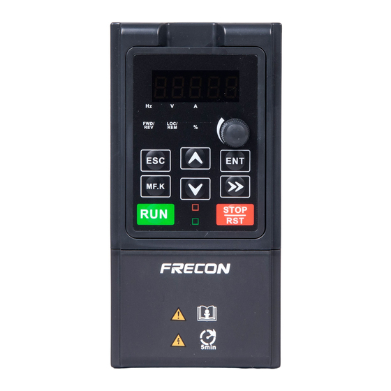
- Page 17 FR150A Series Multifunctional Compact Inverter Chapter 3 Operation and display 3.1 Introduction of Keypad As a human-machine interface, you can modify the parameters, monitor the working status and start or stop the inverter by operating the keypad. Its appearance and function area as shown in the following figure: Fig.3-1 Keypad...
- Page 18 FR150A Series Multifunctional Compact Inverter 3.1.2 Keypad Indicators There are 8 Indicators on the keypad, whose descriptions are as shown in Table 3-2. Table 3-2 Description of indicators Indicator Name Meaning ON: currently displayed parameter is Frequency frequency Voltage ON: currently displayed parameter is voltage...
- Page 19 FR150A Series Multifunctional Compact Inverter 3.1.4 Message status A message appears when the state of completion of certain operations. Prompt message characters and their meanings are specified in Table 3-4. Table 3-4 Prompt characters Prompt symbol Meaning Prompt symbol Meaning Motor parameter Err00~Err99...
- Page 20 FR150A Series Multifunctional Compact Inverter 3.3 Viewing Status Parameters There are stop state parameters and running state parameters. It has 4 status parameters in the stop or running state .You can press “>>” on the keypad to display status parameters. Which parameters are displayed is determined by the values of F16.03~F16.06 (Running state parameters 1~4)...
- Page 21 FR150A Series Multifunctional Compact Inverter Method 1. Setting F00.01=0 to basic menu Method 1. Setting F00.01 to shortcut menu Method 2. Long press when display Switch Method 2. Long Press second level menu, switch to shortcut menu when display second level...
- Page 22 FR150A Series Multifunctional Compact Inverter Chapter 4 List of Parameter Group F00~F16 are standard function parameters. Group U00 is status monitoring parameters. Group U01 is fault record parameters. The symbols in the function code table are described as follows: "△ " means the value of this parameter can be modified in stop and running status of drive;...
- Page 23 FR150A Series Multifunctional Compact Inverter 4.1 Five LED (digital) display indicators Ten thousand’s Unit’s place place Thousand’s place Hundred’s place Ten’s place Fig.4-1 LED indicators 4.2 Standard Function Parameters Table 5-1 Standard Function Parameters Param. Parameter Name Setting Range Default...
- Page 24 FR150A Series Multifunctional Compact Inverter 2: Derating of fixed carrier 3: Derating of random carrier Ten’s place: PWM modulation mode 0: Seven-segment mode 1: Five-segment mode 2: Five-segment and seven-segment automatic switchover Hundreds place: over-modulation adjustment 0: Invalid 1~9: 1.01~1.09 times of...
- Page 25 FR150A Series Multifunctional Compact Inverter 6: Process PID output 7: X7/HI pulse input 8: Analog input AI2 Digital Setting of Master 50.00H △ F01.02 0.00~Fmax Frequency 0: Auxiliary digital setting (F01.04) 1: keypad potentiometer 2: Analog input AI1 3: Communication Auxiliary Frequency F01.03...
- Page 26 FR150A Series Multifunctional Compact Inverter 1:Grounding short-circuit detection before the first starts 2:Grounding short-circuit detection before each starts Hundred’s place: Speed tracking 0:Track from zero speed 1:Track from max frequency Thousand’s place: Select if Jog function takes the priority 0:Disable 1:Enable Ten thousand’s place: Tracking...
- Page 27 FR150A Series Multifunctional Compact Inverter △ F03.07 Decel time 3 15.0s 0.0~6000.0s △ F03.08 Jog accel time 0.0~6000.0s 15.0s △ F03.09 Jog decel time 15.0s 0.0~6000.0s 0: Linear Accel/Decel F03.10 Accel/Decele curve × 1: S-curve Accel/Decel Initial segment time of F03.11...
- Page 28 FR150A Series Multifunctional Compact Inverter the current frequency) 28: Swing frequency reset(output the central frequency) 29: Run command switched to keypad control 30: Run command switched to terminal control 31: Run command switched to communication control 32: Count input 33: Count clear...
- Page 29 FR150A Series Multifunctional Compact Inverter frequency change step 200ms size 0: Level effective 1: Edge trigger +Level Terminal action selection F04.18 effective(When power on) × when power on 2: Edge trigger +Level effective(Every start) Delay time before △ F04.19 0.0~300.0s 0.0s...
- Page 30 FR150A Series Multifunctional Compact Inverter Hundred’s place: Relay 1 output (same as unit's place) Thousand’s place: Relay 2 output (same as unit's place) Detection width of F05.09 5.00Hz × 0.00~20.00Hz frequency attained 30.00H F05.10 FDT1 upper bound 0.00~Fmax × 30.00H F05.11...
- Page 31 FR150A Series Multifunctional Compact Inverter Input of inflection point Minimum input of curve AI1~Input △ F06.10 100.0% 1 of curve AI2 of inflection point 2 of curve AI2 Set value corresponding △ F06.11 to input of inflection 100.0% -100.0~100.0% point 1 of curve AI2...
- Page 32 FR150A Series Multifunctional Compact Inverter △ F07.03 AO1 offset 0.0% -100.0~100.0% △ F07.04 AO1 gain -2.000~2.000 1.000 △ F07.05 AO1 filtering time 0.000s 0.000~10.000s Group F08 Parameters of Motor 1 0: Three phase asynchronous motors 1: Reserved 2: Single phase asynchronous F08.00...
- Page 33 FR150A Series Multifunctional Compact Inverter Multi-point V/F voltage 1 △ F09.04 0.0% 0.0~100.0 (V1) Multi-point V/F frequency △ F09.05 F09.03~F09.05 5.00Hz 2(F2) Multi-point V/F voltage 2 △ F09.06 14.0% 0.0~100.0 (V2) Multi-point V/F frequency 25.00H △ F09.07 F09.05~F09.09 3(F3) Multi-point V/F voltage 3 △...
- Page 34 FR150A Series Multifunctional Compact Inverter gain Ti2 △ F10.15 Excitation gain coefficient 50.0~200% 100% 0: Set by F10.17 1: Keypad potentiometer 2: AI1 Torque setting source F10.16 × under torque control 3: AI2 5: Pulse setting ( DI7/HI ) 6: Communication setting △...
- Page 35 FR150A Series Multifunctional Compact Inverter 3: Fault protection disabled Ten's place: Power input phase Loss (Err09)(Same as unit's place ) Hundred's place: Power output phase loss(Err10)(Same as unit's place ) Thousand's place: Motor overload (Err11)(Same as unit's place ) Ten thousand's place: Inverter...
- Page 36 FR150A Series Multifunctional Compact Inverter Ten's place : compared object 0: Rated current of motor 1: Rated current of drive Hundred's place: report fault or not 0: Not report fault 1: Report fault 2:Show warning Thousand's place: deceleration or 0: Deceleration...
- Page 37 FR150A Series Multifunctional Compact Inverter △ F12.01 Reference 1 0.0% -100.0~100.0% △ F12.02 Reference 2 -100.0~100.0% 0.0% △ F12.03 Reference 3 0.0% -100.0~100.0% △ F12.04 Reference 4 -100.0~100.0% 0.0% △ F12.05 Reference 5 -100.0~100.0% 0.0% △ F12.06 Reference 6 -100.0~100.0% 0.0%...
- Page 38 FR150A Series Multifunctional Compact Inverter △ F12.28 Running time of step 10 0.0s(h) 0.0~6000.0s(h) △ F12.29 Running time of step 11 0.0~6000.0s(h) 0.0s(h) △ F12.30 Running time of step 12 0.0s(h) 0.0~6000.0s(h) △ F12.31 Running time of step 13 0.0~6000.0s(h) 0.0s(h)
- Page 39 FR150A Series Multifunctional Compact Inverter 1:Hold when power off Ten’s place: select if it can be reduced to negative 0:Disable 1:Enable UP/DOWN speed of △ F12.51 0.0~100.0% (0.0%Invalid) 0.0% Multi-reference Group F13 Process PID 0: F13.01 digital setting 1: keypad potentiometer 2: AI1 F13.00...
- Page 40 FR150A Series Multifunctional Compact Inverter 1:limited Hundred’s place: UP/DOWN digital given of PID 0:Zero clearing when power off 1:Hold when power off Thousand’s place: PID feedback loss detection when stop 0:Not detect when stop 1:detect when stop Then thousand’s place: action for...
- Page 41 FR150A Series Multifunctional Compact Inverter 2: Refer to Ai1 channel 3: Refer to AI2 channel 4: Refer to AI3 channel F14.08 Set count value 1~65535 1000 × F14.09 Designated count value 1000 × 1~65535 Dormant frequency (F14.12)~ △ F14.10 Wakeup frequency 0.00Hz...
- Page 42 FR150A Series Multifunctional Compact Inverter frequency numerical 1: Absolute value attribute Group F16 Keys and Display of Keypad Parameters 0: No function 1: Jog F16.00 MF.K key setting 2: Forward/reverse switchover × 3: Run command sources shifted 4: Jog reverse Unit’s place: Function selection of...
- Page 43 FR150A Series Multifunctional Compact Inverter Parameter 0 User-defined Display △ F17.01 01.01 00.00~49.99 Parameter 1 User-defined Display △ F17.02 00.00~49.99 01.02 Parameter 2 User-defined Display △ F17.03 01.08 00.00~49.99 Parameter 3 User-defined Display △ F17.04 00.00~49.99 01.09 Parameter 4 User-defined Display △...
- Page 44 FR150A Series Multifunctional Compact Inverter User-defined Display △ F17.29 00.00 00.00~49.99 Parameter 29 F22Group:Virtual IO Function selection of F22.00 The same as function code F04.00 × virtual VDI1 terminal Function selection of F22.01 The same as function code F04.00 ×...
- Page 45 FR150A Series Multifunctional Compact Inverter ⊙ U00.00 Running frequency 0.00Hz 0.00~Fup ⊙ U00.01 Set frequency 0.00~Fmax 0.00Hz ⊙ U00.02 Output voltage 0.0V 0~660V ⊙ U00.03 Output current 0.0~3000.0A 0.0A ⊙ U00.04 Output power 0.0~3000.0kW 0.0kW Estimated Motor ⊙ U00.05 0rpm 0~60000rpm...
- Page 46 FR150A Series Multifunctional Compact Inverter Err11: Motor overload Err12: Inverter overload Err13: External equipment fault Err14: Module overheat Err15: EEPROM read/write fault Err16: Motor auto-tuning cancelled Err17: Motor auto-tuning fault Err18: Communication overtime Error Err19: PID feedback loss Err20: Continuous running time...
- Page 47 FR150A Series Multifunctional Compact Inverter Bus voltage when ⊙ U01.13 before-previous fault 0~1200V occurred Cumulative running time ⊙ U01.14 when before-previous 0~65535h fault occurred Previous 3 categories of ⊙ U01.15 The same with U01.00 Err00 faults Previous 4 categories of ⊙...
- Page 48 FR150A Series Multifunctional Compact Inverter 4.3 Pulse Feedback Special purpose function 0: Invalid × H00.00 enable 1:Valid Select whether to enable pulse feedback function or not. Pulse number per △ H00.01 1~10000 revolution Set pulse number of per revolution. Then Revolution = (Total pulse)/(H00.01);...
- Page 49 FR150A Series Multifunctional Compact Inverter Chapter 5 Maintenance and Troubleshooting FR150A inverter provides a number of warning information and protection, when a fault occurs, the protective function is activated, the inverter will stop output, inverter fault relay contact, and in the inverter displays the fault code on the display panel.
- Page 50 FR150A Series Multifunctional Compact Inverter 1: The input voltage is too 1: Adjust the voltage to high. normal range. 2: An external force drives the 2: Cancel the external force motor during deceleration. Decel or install the braking resistor. Err05...
- Page 51 FR150A Series Multifunctional Compact Inverter small power class. higher power class. 1: The load is too heavy or 1: Reduce the load and locked-rotor occurs on the check the motor and Err12 Inverter overload motor. mechanical condition. 2: The AC drive model is of too 2: Select an AC drive of small power class.
- Page 52 FR150A Series Multifunctional Compact Inverter Module temperature The temperature sensor Err24 For technical support detection failure or cable break disconnection Check that the load is The AC drive running current disconnected or the setting Err25 Load becoming 0 is lower than F11.22 F11-22 and F11-23 is correct.
- Page 53 FR150A Series Multifunctional Compact Inverter Appendix A: Modbus Communication Protocol 1. Application Scope 1. Applicable series: FRECON FR series inverter 2. Applicable network: Support Modbus protocol, RTU format, with single-master/multi-slave Communication network of RS485 bus. The typical RTU message frame format:...
- Page 54 FR150A Series Multifunctional Compact Inverter 4.3 Allocation of Register Addresses name Description High byte function code group number, F00~F31, U00, U01, respectively, corresponding to the high byte address is 00H~1FH, 30H, 31H. Low byte of the group function code number, from 0 to 99 corresponding to the low byte address is 00H~63H.
- Page 55 FR150A Series Multifunctional Compact Inverter 4.5 The status and function of the read address Description: (read only) Status word address functional status word 0000H: parameter setting 0001H: slave run 0002H: JOG operation 2100H 0003H: learning run 0004H: Slave parking 0005H: JOG parking...
- Page 56 FR150A Series Multifunctional Compact Inverter Command code 0x06: Write single function code or control parameter of inverter. ADU Item Byte No. Range Master requests: Address of slave 0~127 Command Code 0x06 Register start address 0x0000~0xFFFF The number of register 0x0000~0xFFFF...
- Page 57 FR150A Series Multifunctional Compact Inverter unsigned int CRC_Cal_Value (unsigned char *Data, unsigned char Length) unsigned int crc_value = 0xFFFF; Int i = 0; while (Length--) crc_value ^= *Data++; for (i=0; i<8; i++) If (crc_value & 0x0001) crc_value = (crc_value>>1) ^ 0xa001;...
- Page 58 FR150A Series Multifunctional Compact Inverter 8. Illustration 1, No. 01 reads the output frequency value (U00.00), returned 5000, that 50.00Hz. To send data: 01 03 30 00 00 01 8B 0A The received data is: 01 03 02 13 88 B5 12 2, No.
- Page 59 FR150A Series Multifunctional Compact Inverter Appendix B: Braking Resistor When deceleration or rapid deceleration in high inertia load, motor will be in the state of power generation, the load power will pass the converter part to inverter DC part lead to the rise of inverter bus voltage, when it is higher than a certain value, inverter will alarm with voltage fault, even damage the power module, so we must configure braking system.
Need help?
Do you have a question about the FR150A Series and is the answer not in the manual?
Questions and answers
How to connect a single phase motor to a 3 phase vfd
Frecon inverter not switching on
How to clear error code 12
What does error 12 or A33 indicate on 150series vfd inverter