Table of Contents
Advertisement
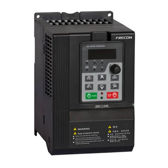
FR200 series inverters fast installation and commissioning guide
Step 1. Checking the inverter model No.
Master series code of
Product:
FR200: Vector control
inverter
Industry-specific series
code:
None:Standard Machine
A~Z:Industry-specific
retention
Input voltage:
2: 220V(-15%~+30%)
4: 380V(-15%~+30%)
Step 2. Wirings
By step 1 to check and confirm that the purchased inverter is what user need, and
then wirings as below:
1. Main circuit wiring
Power
Terminal marks
R/L1、S/L2、T/L3
U/T1、V/T2、W/T3
(+)、(-)
PB
2. Control circuit wirings
Different control circuit wirings for different applications, for FRECON product
quick-menu, here take some normal-used wirings as example below:
FR200□-4T-7.5G/011PB
Figure 1 Produce Model No. Naming Rule
Braking Resistor(Optional spares)
MCCB
L1
L2
L3
Figure 2 Main Circuit Wirings
Designation and function of terminals.
AC power input terminals for connecting to 3-phase AC380V power
supply.
AC output terminals of inverter for connecting to 3-phase induction
motor.
Positive and negative terminals of internal DC bus.
Positive and negative terminals of internal DC bus. Connecting
terminals of braking resistor. One end connected to + and the other to
PB.
Grounding terminal.
FR200 Series Vector control inverter
(+)
PB
U
V
Inverter
W
- 1 -
Brake unit:
None: No Braking Unit
B: Built-in brake unit(30kW
following built,37 ~ 75kW optional
built,No built above 90kW)
Adaptable Motor (kW)And Type of
Motor:7.5G:7.5kW(General type)
011P:11kW(Fan pump type)
Input voltage phases:
S:Single-phase
T:Three-phase
M
Advertisement
Table of Contents

Related Manuals for Frecon FR200 Series


Summary of Contents for Frecon FR200 Series
- Page 1 One end connected to + and the other to Grounding terminal. 2. Control circuit wirings Different control circuit wirings for different applications, for FRECON product quick-menu, here take some normal-used wirings as example below: - 1 -...
- Page 2 +10V R1A R1B R1C Figure 3 FR200 series Control Terminal Diagram 2.1 Frequency given by keypad potentiometer, start or stop the machine controlled by RUN and STOP button on keypad. Control circuits no need to be wired, directly work with power on.
- Page 3 FR200 Series Vector control inverter F01.01 Main frequency source given mode 6: Process PID 1: External terminal (LED light F02.00 Start/stop command source selection turn on) F13.01 PID Digital Given 25.0% 0.0~100.0% F13.08 Proportional Gain Kp1 0.0~100.0 F13.09 Integration Time Ti1 0.01~10.00s...
- Page 4 FR200 Series Vector control inverter Figure 7 Operation panel diagram 3.1 Operation panel button and potentiometer function There are 8 buttons and 1 analog potentiometer, functions of every button as table 1. Table 1 Operation Panel Buttons Function Table Symbol...
- Page 5 FR200 Series Vector control inverter Menu Quick Menu Basic Menu Mode Display F01.01. F01.01 Function code last digit no Difference Function code last decimal point, flash. digit with decimal point, no flash. 1、Press , set 1、Press , switch up or...
- Page 6 FR200 Series Vector control inverter 5: PLC 6: Process PID output 7: X7/HI pulse input 8:AI2 9:AI3 0: Keypad control (LED off) 1: Terminal control (LED on) F02.00 Run command × 2: Communication control (LED blinking) 0: Forward △ F02.01...
- Page 7 FR200 Series Vector control inverter 3: Fault protection disabled Ten's digit :Power input phase Loss (Err09)(Same as unit's place ) Hundred's digit :Power output phase loss(Err10)(Same as unit's place ) Thousand's digit:Motor overload (Err11)(Same as unit's place ) Ten thousand's digit:Inverter overload(Err11)(Same as unit's place ) 0: F13.01 digital setting...
-
Page 8: Preface
Thank you for choosing FRECON developed and produced FR200 series vector control inverter. FR200 series vector control inverter is mainly positioned as a high-end market for OEM customers and the specific requirements of fan and pump load applications,its flexible design, both embedded SVC and VF control in one,can be widely used for speed control accuracy, torque... - Page 9 FR200 Series Vector control inverter - 9 -...
-
Page 10: Table Of Contents
FR200 Series Vector control inverter Contents Preface ................................- 8 - Contents ..............................- 10 - Chapter 1 Safety Precautions ....................... - 12 - 1.1 Safety Considerations ........................- 12 - 1.2 Precautions ............................. - 14 - Chapter 2 Product Information ......................- 16 - 2.1 Nameplate information ........................ - Page 11 FR200 Series Vector control inverter Group F08 Parameters of Motor 1 ....................- 104 - Group F09 V/f Control Parameters of Motor 1 ................. - 105 - Group F10 Vector Control Parameters of Motor 1 ................- 108 - Group F11 Protection Parameters ....................- 110 - Group F12 Multi-Reference and Simple PLC Function ..............
-
Page 12: Chapter 1 Safety Precautions
Users are requested to read this chapter carefully when installing, commissioning and repairing this product and perform the operation according to safety precautions as set forth in this chapter without fail. FRECON will bear no responsibility for any injury and loss as a result of any violation operation. - Page 13 R1A、 R1B、 R1C andR2A、 R2B、 R2C. Failure to comply may result in equipment damage. ◆Since all adjustable frequency AC drives from FRECON have been subjected to hi-pot test before delivery, users are prohibited from implementing such a test on this equipment.
-
Page 14: Precautions
1.2.11 Altitude De-rating In places where the altitude is above 1000 m and the cooling effect reduces due to thin air, it is necessary to de-rate the AC drive. Contact FRECON for technical support. 1.2.12 some special usages If wiring that is not described in this manual such as common DC bus is applied, contact the agent or FRECON for technical support. - Page 15 FR200 Series Vector control inverter The standard parameters of the adaptable motor have been configured inside the AC drive. It is still necessary to perform motor auto-tuning or modify the default values based on actual conditions. Otherwise, the running result and protection performance will be affected.
-
Page 16: Chapter 2 Product Information
FR200 Series Vector control inverter Chapter 2 Product Information 2.1 Nameplate information Fig.2-1 Nameplate information Model Explanation Model show on product nameplate contains information below FR200□-4T-7.5G/011PB Brake unit: Master series code of None: No Braking Unit Product: B: Built-in brake unit(30kW FR200: Vector control following built,37 ~ 75kW optional... -
Page 17: Information Of Fr200 Product Model
FR200 Series Vector control inverter 2.2 Information of FR200 Product Model Table 2-1 FR200 Product model and technical data Power Rated Rated output Model No. Applicable motor capacity Input current current 3-Phase:220V,50/60Hz Range:-15%~+30% FR200-2T-0.7B 0.75 FR200-2T-1.5B FR200-2T-2.2B 11.6 11.7 FR200-2T-4.0B 3.7、4... -
Page 18: Technical Features Of Fr200
FR200 Series Vector control inverter FR200-4T-355G/400P 624* FR200-4T-400G/450P 690* FR200-4T-450G/500P 765* FR200-4T-500G/560P 835* FR200-4T-560G/630P 960* FR200-4T-630G/710P 1050* 1100 means FR200-2T-045 and FR200-4T-90G/110P or above is provided with an external-mounted DC reactor in shipment as default 2.3 Technical Features of FR200... - Page 19 FR200 Series Vector control inverter -type、1.8 Th -type、2 Th -type) Acceleration Line or curve acceleration and deceleration mode. Four kinds of acceleration and deceleration time,Ramp deceleration Time Range :0.0~6000.0s Curve DC brake start frequency: 0.00~600.00Hz DC brake DC brake time:0.0s~10.0s DC brake current:0.0%~150.0%...
-
Page 20: Parts Drawing
FR200 Series Vector control inverter sensor-less vector control. Provide fault protection dozen: Overcurrent、 Overvoltage、Undervoltage、 Protection function Overtemperature、Overload Etc Protection. LED Display Display Parameters Key lock and Realize some or all of the keys locked, scope definition function Display and section keys to prevent misuse... -
Page 21: Configuration, Mounting Dimensions And Weight
FR200 Series Vector control inverter Fan cover Mounting holes Keypad Middle case Upper case Lower case Nameplate Cover Dust cover (Optional) Stringing board Base plate Cooling air inlet Mounting Bracket (Optional) ~ Fig 2-3-b 4 15kW Outline Mounting holes Fan cover... - Page 22 FR200 Series Vector control inverter b: 18.5~400W Dimensions and wall mounting dimensions ~ ~ Fig 2-6 18.5 132KW Wall installation diagram(1) 400kW Wall installation diagram(2) Table 2-3 Configuration, mounting dimensions and weight External and installation dimensions(mm) Weight Mounting Model NO.
-
Page 23: Flange Mounting Dimensions
FR200 Series Vector control inverter FR200-4T-160G/185P FR200-4T-185G/200P 1107 1078 138.5 FR200-4T-200G/220P FR200-4T-220G/250P FR200-4T-250G/280P 1160 1130 FR200-4T-280G/315P FR200-4T-315G/355P FR200-4T-355G/400P 1140* 1110 FR200-4T-400G/450P note: 315 ~ 400 kw height size does not contain the base height, dc reactor can be installed in a gutter or rack, if the vertical installation, need to purchase the base (dc reactor can be installed in the base), base height is 400 mm. - Page 24 FR200 Series Vector control inverter b: 18.5~132kW dimensions Flange mounting ~ Fig 2-9 18.5 132kW Flange mounting Table 2-4 Flange mounting dimensions table External and installation dimensions(mm) Model.NO 3-Phase:220V,50/60Hz Range:-15%~+30% FR200-2T-0.7B FR200-2T-1.5B FR200-2T-2.2B FR200-2T-4.0B FR200-2T-5.5B FR200-2T-7.5B FR200-2T-011B 40.5 460.5 FR200-2T-015B FR200-2T-018 591.5...
-
Page 25: External Dimensions Of Keypad
FR200 Series Vector control inverter 2.7 External Dimensions of Keypad ~ Fig 2-10-a 0.75 2.2KW Keyboard size diagram ~ Fig 2-10-b 4.0 630KW Keyboard size diagram External keyboard installation instruction: 1. first install the panel according to inverter’s power range corresponding to the size of hole as shown on scheme 2-11, After that insert keyboard pad into the mounting panel and then insert the keyboard module into the keyboard pad.(Before removing the keyboard pad, first remove the... -
Page 26: 75Kw Keypad Plate Open Operation
FR200 Series Vector control inverter 2.8 18.5-75kW Keypad plate open operation screw Fig 2-12 1. Getting keypad out from keypad plate; 2.Again disconnect the network cable from the keyboard, insert the network cable into the cabinet through keypad pad hole 3.To open the front cover remove two bottom screws... -
Page 27: Chapter 3 Installation And Wiring
Multi- FR200 can be installed in parallel horizontally e and vertically. See followings for specific space requirement, heat dissipating capacity and mass airflow. FR200 series inverter installation of the following three: Wall mounting: (suitable for 400KW (inclusive)). Wall-mounted: (suitable for 132KW (inclusive)). - Page 28 FR200 Series Vector control inverter 3.2.1 Single installation Ventilation clearance Ventilation clearance Fig.3-2 Single inverter mounting orientation and space requirements 3.2.2 Multiple installations a. Multiple parallel installations Ventilation clearance Ventilation clearance Fig.3-3 multiple inverters installed direction and space requirements Air Outlet Direction Baffle Fig.3-4 Multiple inverters installed Upper and lower mounting direction and space...
-
Page 29: Fixed Manner
FR200 Series Vector control inverter Table 3-1 Requirement of minimum mounting clearances Mounting clearances (mm) Drive model ≥50 ≥100 0.75~15kW ≥50 ≥200 18.5~45kW ≥150 ≥300 55kW and above 3.3 Fixed manner a. Wall installation Wall mounting dimensions refer to Chapter II(table 2-3),As shown in Fig drilling four holes in the mounting surface,Put the inverter against the panel and mate 4 holes, and then tighten screws in... -
Page 30: Remove & Mount Keypad And Cover
FR200 Series Vector control inverter The machine Components Mounting panel Hole B Hole B Hex nuts Place the hex Hole B Hole B nut groove Mounting Bracket Through the corner four M5 screw M5 screw fastening machines Fig.3-6 (a)0.75~15kW Wall installation... - Page 31 FR200 Series Vector control inverter b. Mount keypad: Assemble keypad. See following Figure: Place keypad in the slot in Direction 1, and then press the keypad in Direction 2 until it clicks into right place. Fig.3-7(a) Remove keypad Fig.3-7(b) Mount keypad c.External remote operation panel operation method: Remove the operation panel as shown in fig...
- Page 32 FR200 Series Vector control inverter Screw Fig.3-7(d) Open cover e. Assemble keypad: See following Figure: Place the upper buckle of the terminal cover in the slot of upper housing in Direction 1, and then press the two lower buckle of terminal cover I Direction 2 until it clicks into right place of upper housing.
-
Page 33: Dust Cover Installation And Removal(Optional Accessories
FR200 Series Vector control inverter Screw Fig.3-7(f) Disassemble and installation of the cover g. Stringing board disassembly and installation:Disassemble board first when stringing wire,When connected input and output cables, the Stringing board clicks into place. Referring to fig 3-7(g) Fig.3-7(g) Stringing board disassembly and installation 3.5 Dust cover installation and removal(Optional accessories)... -
Page 34: Configuration Of Peripheral Devices
FR200 Series Vector control inverter 3.6 Configuration of Peripheral Devices power source circuit breaker contactor Inverter +/PB Braking U/V/W resistor Input chokes R/S/T Output filter Input filter Output AC reactor motor Fig.3-9 Standard configuration of peripheral device Table 3-2 Instructions of peripheral devices... - Page 35 FR200 Series Vector control inverter Output filter and radiated interference of the drive to Output filter peripheral devices Avoid the motor insulation damage result from harmonic voltage Reduce frequent protection from the Output AC drive caused by leakage current In case the cable...
- Page 36 FR200 Series Vector control inverter FR200-4T-110G/132P FR200-4T-132G/160P FR200-4T-160G/185P FR200-4T-185G/200P FR200-4T-200G/220P 150*2 FR200-4T-220G/250P 150*2 FR200-4T-250G/280P 185*2 95*2 FR200-4T-280G/315P 185*2 95*2 FR200-4T-315G/355P 150*3 75*3 FR200-4T-355G/400P 150*4 75*4 FR200-4T-400G/450P 1000 1000 150*4 75*4 FR200-4T-450G/500P 1200 1200 180*4 90*4 FR200-4T-500G/560P 1200 1200 180*4 90*4...
- Page 37 FR200 Series Vector control inverter 450kw ACL-4T-450 Built-in OCL-4T-450 500kw ACL-4T-500 Built-in OCL-4T-500 560kw ACL-4T-560 Built-in OCL-4T-560 630kw ACL-4T-630 Built-in OCL-4T-630 Note: 1. Input reactor,input rated voltage drop 2%±15%;Output reactor,input rated voltage drop 1%± 15%。 2. Input and output reactors are external and optional 3.6.3 Filter...
-
Page 38: Wiring Way
FR200 Series Vector control inverter Note: 1. Can meet EMI C2 after installing input filter 2. Input and output filter are external and optional 3.7 Wiring way Braking resistor MCCB U/T1 R/L1 Three-phase V/T2 380V S/L2 50/60Hz FR200 W/T3 T/L3... -
Page 39: Terminal Configuration
FR200 Series Vector control inverter profile)or Comply with manual drive. 3.8 Terminal Configuration 3.8.1 Main Circuit Terminals a: 0.75~2.2KW Main Circuit Terminals Upload and Control circuit download interfaces terminals Main circuit terminals T U V (+) (-) POWER Fig.3-11 0.75~2.2kW Schematic of main circuit terminals b: 4~15KW Main Circuit Terminals... - Page 40 FR200 Series Vector control inverter Solution 2: R/L1 S/L2 T/L3 U/T1 V/T2 W/T3 (+) (-) POWER MOTOR Fig.3-14 18.5~30kW Schematic of main circuit terminals d:37-75kW Main Circuit Terminals R/L1 S/L2 T/L3 U/T1 V/T2 W/T3 POWER MOTOR Fig.3-15 37~75kW Schematic of main circuit terminals...
- Page 41 FR200 Series Vector control inverter f:315-400kW Main Circuit Terminals R/L1 S/L2 T/L3 POWER POWER U/T1 V/T2 MOTOR Fig.3-17 315~400kW Schematic of main circuit terminals g:450-630kW Main Circuit Terminals V/T2 U/T1 W/T3 MOTOR POWER Fig.3-18 450~630kW Schematic of main circuit terminals...
- Page 42 FR200 Series Vector control inverter ◆ The capacitor or surge absorber cannot be connected to the output side of the AC drive. Otherwise, it may cause frequent AC drive fault or even damage the AC drive. If the motor cable is too long, electrical resonance will be generated due to the impact of distributed capacitance.
- Page 43 FR200 Series Vector control inverter Switch input DI5- COM terminals 5 Switch input DI6- COM terminals 6 Switch input Besides features of DI1–DI6, it can be terminals 7 OR DI7/HI-COM used for high-speed pulse input. High-speed Maximum input frequency: 100 kHz pulse input Output voltage range:...
- Page 44 FR200 Series Vector control inverter <20m <20m +10V +10V FR200 FR200 DC 0~10V 1kΩ~5kΩ DC 0~10V (a) Fig.3-20 Analog input terminal wiring diagram 2)Instructions of Digital Input/output Terminals Digital input & output signals cables should be as short as possible, shielded, and their shielded layers should be properly grounded close to the side of drive.
- Page 45 FR200 Series Vector control inverter +24V +24V External External FR200 FR200 Jumper controller controller Optocoupler Optocoupler 20~30V Optocoupler Optocoupler DI7/HI DI7/HI (b)External power supply (a) Internal power supply Fig.3-22 External power supply open collector NPN connection ATTENTION: When external power supply is utilized, the jumper between +24V and PLC must be removed. The voltage range of external power supply should be DC20~30V, otherwise normal operation could not...
- Page 46 4)Wiring instruction of relay output terminal Control boards of FR200 series drives are provided with two programmable relay dry contact outputs. One relay contacts are R1A/R1B/R1C, whose R1Aand R1C are normally open, while R1B and R1C are normally closed.
- Page 47 FR200 Series Vector control inverter Fig.3-26 4.0~15kW RFI jumper schematic 75~132KW jumper method: Terminal plug is jumped state, unplug the state is not jumper RFI jumper after RFI jumper before Fig 3-27 37~75kW Short-circuit diagram ATTENTION: 1. When power is applied to the AC motor drive, do not cut off the RFI jumper.
-
Page 48: Emi Solutions
FR200 Series Vector control inverter 3.9 EMI Solutions Due to its working principle, the drive will inevitably produce certain noise that may influence and disturb other equipment. Moreover, since the internal weak electric signal of drive is also susceptible to the interference of drive itself and other equipment, EMI problems shall be inevitable. In order to... - Page 49 FR200 Series Vector control inverter equipment via ground loop. Such a leakage current may result in malfunction of RCD and other equipment. The higher the carrier frequency of drive is, the bigger the ground leakage current would be. The longer the motor cables and the bigger the parasitic capacitances are, the bigger the ground leakage current would be.
-
Page 50: Chapter 4 Operation And Display
FR200 Series Vector control inverter Chapter 4 Operation and display 4.1 Introduction of Keypad As a human-machine interface, you can modify the parameters, monitor the working status and start or stop the inverter by operating the keypad. Its appearance and function area as shown in the following figure:... - Page 51 FR200 Series Vector control inverter 4.1.2 Keypad Indicators There are 8 Indicators on the keypad, whose descriptions are as shown in Table 4-2. Table 4-2 Description of indicators Indicator Name Meaning ON: currently displayed parameter is Frequency frequency Voltage ON:currently displayed parameter is voltage...
-
Page 52: Viewing And Modifying Function Codes
FR200 Series Vector control inverter 4.1.4 Message status A message appears when the state of completion of certain operations. Prompt message characters and their meanings are specified in Table 4-4. Table 4-4 Prompt characters Prompt symbol Meaning Prompt symbol Meaning Motor parameter Err00~Err99... -
Page 53: Motor Auto-Tuning
FR200 Series Vector control inverter status parameters. Which parameters are displayed is determined by the values of F16.03~F16.06 (Running state parameters 1~4) 、F16.07~F16.10(stop state parameters1~4) ,it can select the U00 group. 4.4 Motor Auto-tuning Tuning is valid only when the keyboard command mode. Set tuning mode (stationary or rotating), press the ENT key to confirm, the keyboard will display TUNE, then press the RUN key, the inverter will drive motor acceleration and deceleration, positive inversion operation,and the run indicator lights. -
Page 54: Shortcut Menus Function Code Description
FR200 Series Vector control inverter 4.7 Shortcut menus function code description Factory setting mode is changed to be shortcut menu mode (F00.01=1) in the software version above V1.07, group 17 is for the parameters of shortcut menu. The difference of display between shortcut manual and basic menu is in the second level menu, please refer to below the details of difference and the switching method. -
Page 55: Chapter 5 List Of Parameter
FR200 Series Vector control inverter Chapter 5 List of Parameter Group F00~F17 are standard function parameters. Group U00 is status monitoring parameters. Group U01 is fault record parameters. The symbols in the function code table are described as follows: "△ " means the value of this parameter can be modified in stop and running status of drive;... -
Page 56: Standard Function Parameters
FR200 Series Vector control inverter 5.1 Standard Function Parameters Table 5-1 Standard Function Parameters Param. Parameter Name Setting Range Default Attr Group F00: System Parameters Setting of User F00.00 0~65535 × Password 0: Display all parameters 1: Only display F00.00, F00.01 and user-defined parameters F00.01... -
Page 57: Group F00 Frequency Command
FR200 Series Vector control inverter Decade: PWM modulation mode 0: Seven-segment mode 1: Five-segment mode 2: Five-segment and seven-segment automatic switchover Hundreds place: over-modulation adjustment 0: Disabled 1: Enabled Model △ F00.13 Carrier frequency 0.700~16.000kHz defined Upper carrier F00.14 0.700~16.000kHz 8.000kHz... - Page 58 FR200 Series Vector control inverter 8:AI2 9:AI3 Digital Setting of Master △ F01.02 0.00~Fmax 0.00Hz Frequency 0: Auxiliary digital setting (F01.04) 1: keypad potentiometer 2: Analog input AI1 3: Communication Auxiliary Frequency F01.03 4: Multi-reference × Command Source 5: PLC...
-
Page 59: Group F03 Accel/Decel Parameters
FR200 Series Vector control inverter 1: Coast to stop Initial frequency of stop F02.13 2.00Hz × 0.01~50.00Hz DC braking F02.14 Stop DC braking current 0.0~150.0% 0.0% × Waiting time of stop DC F02.15 0.0s × 0.0~30.0s braking F02.16 Stop DC braking time 0.0s... - Page 60 FR200 Series Vector control inverter 10: Terminal UP 11: Terminal DOWN 12: UP/DOWN (including ∧/∨ key) adjustment clear 13: Multi-step frequency terminal 1 14: Multi-step frequency terminal 2 15: Multi-step frequency terminal 3 16: Multi-step frequency terminal 4 17: Accel/Decel time determinant 1...
-
Page 61: Group F05 Digital Output
FR200 Series Vector control inverter Unit's place: action when stop 0: Clear 1: Holding Terminal UP/DOWN Decade: action on power loss F04.16 frequency adjustment × 0: Clear control 1: Holding Hundreds place: integral function 0: No integral function 1: Integral function enabled Terminal UP/DOWN 1.00Hz/... -
Page 62: Group F06 Analog And Pulse Input
FR200 Series Vector control inverter Detection width of F05.09 5.00Hz × 0.00~20.00Hz frequency attained F05.10 FDT1 upper bound 0.00~Fmax 30.00Hz × F05.11 FDT1 lower bound 0.00~Fmax 30.00Hz × F05.12 FDT2 upper bound 0.00~Fmax 30.00Hz × F05.13 FDT2 lower bound 30.00Hz ×... -
Page 63: Group F07 Analog And Pulse Output
FR200 Series Vector control inverter to input of inflection point 2 of curve AI2 Input of inflection point A of curve Maximum input of curve △ F06.14 100.0% AI2~100.0% Set value corresponding △ F06.15 to maximum input of -100.0~100.0% 100.0%... -
Page 64: Group F08 Parameters Of Motor 1
FR200 Series Vector control inverter F07.01 AO2 output function 1: Output frequency × 2: Command frequency 3: Output current 4: Output voltage 5: Output power 6: Bus voltage 7:+10V Y2/HO output function F07.02 × (when used as HO) 8: keypad potentiometer... -
Page 65: Group F10 Vector Control Parameters Of Motor 1
FR200 Series Vector control inverter 2: 1.2nd power V/F 3: 1.4th power V/F 4: 1.6th power V/F 5: 1.8th power V/F 6: 2.0nd power V/F 7: V/F complete separation 8: V/F half separation 9: 1.2 power inverse curve V/F 10:1.4 power inverse curve V/F 11:1.6 power inverse curve V/F... - Page 66 FR200 Series Vector control inverter 1: torque control ASR low-speed △ F10.01 30.0 0.0~100.0 proportional gain Kp1 ASR low-speed △ F10.02 0.01~10.00s 0.50s integration time Ti1 ASR switching △ F10.03 5.00Hz 0.00~F10.06 frequency 1 ASR high-speed △ F10.04 1~100.0 10.0...
-
Page 67: Group F11 Protection Parameters
FR200 Series Vector control inverter 5: Pulse setting ( DI7/HI ) Group F11 Protection Parameters 0: Current limit disabled F11.00 Current limit control 1: Current limit mode 1 × 2: Current limit mode 2 F11.01 Current limit 100.0~200.0% 150.0% ×... - Page 68 FR200 Series Vector control inverter 0: Fault reported and coast to stop 1: Stop according to the stop mode 2: Fault reported but continue to Ten's digit: Load becoming 0 (Err25) (Same as unit's place) 0: Current running frequency 1: Set frequency...
-
Page 69: Group F12 Multi-Reference And Simple Plc Function
FR200 Series Vector control inverter 0: Disabled Motor temperature sensor F11.35 1: PT100 × type 2: PT1000 0: Disabled Motor temperature sensor F11.36 1: AO1 × current source port 2: AO2 0: Disabled 1: AI1 Motor temperature sensor F11.37 ×... - Page 70 FR200 Series Vector control inverter 3: Run from the fifteenth step “multi-step frequency 15” Hundreds place:power loss memory 0: Memory disabled on power loss 1: Memory enabled on power loss Thousands place: unit of simple PLC running time 0: Second (s) 1: Minute (min) △...
-
Page 71: Group F13 Process Pid
FR200 Series Vector control inverter reference 9 Acceleration/deceleration △ F12.44 time of simple PLC 0~3 reference 10 Acceleration/deceleration △ F12.45 timeof simple PLC 0~3 reference 11 Acceleration/deceleration △ F12.46 time of simple PLC 0~3 reference 12 Acceleration/deceleration △ F12.47 time of simple PLC 0~3... -
Page 72: Group F14 Swing Frequency, Fixed Length, Count And Wakeup
FR200 Series Vector control inverter 0: No switch, determined by parameters Kp1, Ti1 and Td1 F13.14 PID parameter switch 1: Auto switch on the basis of input × offset 2: Switched by terminal PID parameter switchover F13.15 20.0% × 0.0~100.0%... -
Page 73: Group F15 Communication Parameters
FR200 Series Vector control inverter △ F14.12 Dormant frequency 0.00Hz 0.00~Wakeup frequency △ F14.13 Dormant delay time 0.0~6000.0s 0.0s 0:Frequency F14.14 Wake up mode selection × 1:Pressure 0:Frequency F14.15 Dormancy mode selection × 1:Pressure 0:AI1 1:AI2 F14.16 Voltage feedback source ×... -
Page 74: Group F17 User-Defined Display Parameters
FR200 Series Vector control inverter 3: Keys locked other than STOP/RST 4: Keys locked other than >> LED displayed parameters 0~99(correspond U00.00~ △ F16.03 setting 1 on running status U00.99) LED displayed parameters 0~99(correspond U00.00~ △ F16.04 setting 2 on running status U00.99) -
Page 75: Group U00 Status Monitoring
FR200 Series Vector control inverter User-defined Display △ F17.18 08.04 00.00~49.99 Parameter 18 User-defined Display △ F17.19 00.00~49.99 08.05 Parameter 19 User-defined Display △ F17.20 08.30 00.00~49.99 Parameter 20 User-defined Display △ F17.21 00.00~49.99 11.10 Parameter 21 User-defined Display △... -
Page 76: Group U01 Fault Record
FR200 Series Vector control inverter Accumulative power-on ⊙ U00.24 0min 0~65535min time ⊙ U00.25 Accumulative running time 0~6553.5min 0.0min Cumulative power-on ⊙ U00.26 0~65535h time ⊙ U00.27 Cumulative running time 0~65535h ⊙ U00.28 Count value 0~65535 ⊙ U00.29 Length value 0~65535m... - Page 77 FR200 Series Vector control inverter Running frequency ⊙ U01.01 when the latest fault 0.00~Fup 0.00Hz occurred Output current when the ⊙ U01.02 0.0A 0.0~3000.0A latest fault occurred Bus voltage when the ⊙ U01.03 0~1200V latest fault occurred Cumulative running time ⊙...
- Page 78 FR200 Series Vector control inverter Chapter 6 Specification of Parameters Group F00 System Parameters F00.00 Setting of user password Default: 0 Range: 0~65535 Setting of password: A non-zero number could be set as a user password by entering this password into F00.00 and pressing ENT key to confirm once, the password setting will take effect as long as there is no operation on keypad within 2 minutes, or cutting the power off and power up again .
- Page 79 FR200 Series Vector control inverter Requirement to the drive is not rigorous, or using one drive to drive several motors, or it is difficult to identify motor parameters correctly, etc. When motor 1 under V/f control is selected, need to set related parameters Group F09 well.
- Page 80 FR200 Series Vector control inverter The table below specifies the setting range and factory default of PWM carrier frequency of the drives at different power ratings: Power rating of the Range Default inverter ≤15kW 4.000k 0.700k~16.000k 18.5kW~45kW 0.700k~8.000k 4.000k 55kW~75kW 0.700k~6.000k...
- Page 81 FR200 Series Vector control inverter F00.26 Inverter application Range:0~1 Default:0 Inverter application 0:General purpose application 1:Fireworks machine Group F00 Frequency command Switched by Switched by /DOWN terminal Terminal UP terminal Master frequency source Command frequency Auxiliary frequency source frequency Fig. 6-1 Frequency source F01.00...
- Page 82 FR200 Series Vector control inverter Analog input AI1 Analog input AI2 Inverter Fig. 6-2 If 10V power supply inside the drive is used with potentiometer, the connection diagram is shown as Fig. 6-3. Note that the toggle switch should be switched to voltage input side.
- Page 83 FR200 Series Vector control inverter Master frequency command is determined by analog input AI2. 9:AI3 Master frequency command is determined by analog input AI3. Digital setting of master F01.02 Range:0.00~FmaxHz Default:0.00Hz frequency When master frequency source selection F01.01 is set to 1, this parameter value will be the initial value of master frequency command.
- Page 84 FR200 Series Vector control inverter 1. Fup and Fdown shall be set as per motor nameplate parameters and working conditions. Motor shall not work in low frequency for a long time. Otherwise, motor service lifespan will be shortened due to overheating.
- Page 85 FR200 Series Vector control inverter Output frequency(Hz) Time(S) Dead time of forward Dead time of forward and reverse and reverse Fig. 6-4 F02.04 Start mode Range:0~1 Default: 0 0: From start frequency If the DC braking time(F02.08) is set to 0, the AC drive starts to run at the startup frequency(F02.05) and keeps this frequency for a period of time set by F02.06, and then accelerated...
- Page 86 FR200 Series Vector control inverter 0: Ramp to stop Upon the receipt of stop command, drive will gradually decrease output frequency according to the set Decel time, and stop when frequency attains 0. 1: Coast to stop Upon the receipt of stop command, drive will immediately lock the output and the motor will stop with its mechanical inertia.
- Page 87 FR200 Series Vector control inverter brake of high-inertia load or the situations that require quick stop. In such a case, it is necessary to select appropriate dynamic brake resistor and break unit. The AC drives equal and below 30kW is provided with a standard built-in brake unit.
- Page 88 FR200 Series Vector control inverter The 1st section and the last section in accelerating or decelerating are in smooth transition. The acceleration/deceleration curve is similar to S curve. When it is in S curve, the final acceleration/deceleration time= S curve time+ Linear acceleration/deceleration time. See Figure 6-13 for 2 acceleration/deceleration modes.
- Page 89 FR200 Series Vector control inverter Group F04 Digital Input F04.00 Function of terminal DI1 Default:1 Range:0~99 F04.01 Function of terminal DI2 Default:2 Range:0~99 F04.02 Function of terminal DI3 Default:7 Range:0~99 F04.03 Function of terminal DI4 Range:0~99 Default:13 F04.04 Function of terminal DI5 Range:0~99...
- Page 90 FR200 Series Vector control inverter deceleration time selection When "Accel/Decel disabled" terminal is enabled, the drive Acceleration/Decele maintains the present output frequency and no longer ration responds to the change of command frequency. But it will prohibited still perform ramp-down stop when receiving stop command.
- Page 91 FR200 Series Vector control inverter 14.04~F14.06 for details. When the length is attained, digital output terminal "length attained" shall output effective signal. The current length value will be memorized on power loss. Used with "length count" terminal, to clear the length Length clear calculated.
- Page 92 FR200 Series Vector control inverter Acceleration/Deceler Acceleration/Deceler Acceleration/Deceleratio Corresponding ation time ation time n Time Selection Parameters determinant 2 determinant 1 Acceleration/Deceleratio F03.00、F03.01 n time 1 Acceleration/Deceleratio F03.02、F03.03 n time 2 Acceleration/Deceleratio F03.04、F03.05 n time 3 Acceleration/Deceleratio F03.06、F03.07 n time 4 Filtering time of digital F04.10...
- Page 93 FR200 Series Vector control inverter 1: Negative Logic ;< 3V, invalid; > 7V, valid Thousand's digit: AI2 (same as AI1) Ten thousand's digit: AI3 0: Positive logic ;< -6V, valid; > 4V, invalid 1: Negative Logic ;< -6V, invalid; > 4V, valid F04.15...
- Page 94 FR200 Series Vector control inverter The parameters are set as below: Function Code Parameter Name Value Function Description F04.15 Terminal command mode Three-line 1 F04.00 DI1 function selection Forward RUN (FWD) F04.01 DI2 function selection Reverse RUN (REV) F04.02 DI3 function selection...
- Page 95 FR200 Series Vector control inverter Figure 6-11 setting of three-line mode 2 As shown in the preceding figure, if SB1 is ON, the AC drive starts running when SB2 is pressed to be ON; the AC drive instructs forward rotation when K is OFF and instructs reverse rotation when K is ON.
- Page 96 FR200 Series Vector control inverter detection FDT2 output Drive in 0Hz running When be running at 0Hz, this corresponding terminal 1(no output at stop) outputs ON signal. No ON signal will be output at stop. Drive in 0Hz running Outputs ON signal when is running at 0Hz and also outputs 2(output at stop) ON signal at stop.
- Page 97 FR200 Series Vector control inverter 1: Negative logic; ON when no current passes through 0: Positive logic; ON when there is coil excitation 1: Negative logic; ON when there is no coil excitation Wiring diagram of digital output terminal is shown as Fig. 6-12:...
- Page 98 FR200 Series Vector control inverter Output frequency(Hz) FDT upper bound FDT lower bound Time(S) Valid Time(S) Fig. 6-14 F05.14 Consecutive running time Default: 0.0Min Range:0.0~6000.0Min This parameter should be set with digital output terminal “Consecutive running time attained". When current running time attains the value of F05.14, corresponding terminal outputs ON. Current running time is cleared when stop.
- Page 99 FR200 Series Vector control inverter Frequency F05.18 F05.22 FWD/REV Internal operating Brake F05.2 F05.2 F05.2 F05.2 Current F05.19 Fig 6-15 Break control logic scheme 1)After inverter receives a run command, accelerate the run to set F05.18 brake open frequency. 2)After the frequency reaches F05.18 set frequency, inverter keeps constant running and the duration reaches the F05.20 set brake open waiting time, inverter running constant speed continue to...
- Page 100 FR200 Series Vector control inverter Set value corresponding F06.05 to input of inflection Range:-100.0~100.0% Default:75.0% point 2 of curve AI1 Range:Input of inflection point Maximum input of curve F06.06 Default:100.0% 2 of curve AI1~100.0% Set value corresponding to F06.07 Range:-100.0~100.0% Default:100.0%...
- Page 101 FR200 Series Vector control inverter Set frequency F06.07 Fmax 100% F06.05 7.5V Analog input 0.0% 100% F06.00 F06.02 F06.04 F06.06 F06.03 -50% F06.01 -100% Figure 6-16 (2) Range:0.0%~input of F06.08 Minimum input of curve AI2 Default:0.0% inflection point1 of curve AI2 Set value corresponding to F06.09...
- Page 102 FR200 Series Vector control inverter Curve AI2 is defined by F06.08~F06.15. Curve AI3 is defined by F06.16~F06.23. The usage of curve AI2 and curve AI3 is the same as that of curve AI1. Minimum input of curve Range:0.0~Maximum input of F06.24...
- Page 103 FR200 Series Vector control inverter F06.36 defines the filtering time of pulse input terminals DI7/HI. Long filtering time results in strong immunity from interference but slow response, while short filtering time brings rapid response but weak immunity from interference. Group F07 Analog and Pulse Output F07.00...
- Page 104 FR200 Series Vector control inverter This parameter sets the maximum output frequency when Y2/HO terminal is selected as high-speed pulse output. F07.10 HO output filtering time Default:0.010s Range:0.000~10.000s Set the filtering time of HO high-speed pulse output. Filtering can change the change rate of output pulse frequency.
- Page 105 FR200 Series Vector control inverter Before performing complete auto-tuning, properly set the motor type, motor nameplate parameters of F08.00 to F08.07. The AC drive will obtain motor parameters of F08.08 to F08.12 by complete auto-tuning. Set this parameter to 2, and press RUN. Then, the AC drive starts complete auto-tuning.
- Page 106 FR200 Series Vector control inverter 9:1.2 power inverse curve 10:1.4 power inverse curve 11:1.6 power inverse curve 12:1.8 power inverse curve 13:2.0 power inverse curve 9~13 curve is for torque boost,which is rotated 180 degrees along diagonal line of 2~6 curve F09.01...
- Page 107 FR200 Series Vector control inverter Output voltage (V) Rated voltage of motor Output frequency(Hz) Rated frequency of motor Fig. 6-19 ATTENTION: The multi-point V/F curve is set based on the motor's load characteristic. The relationship between voltages and frequencies is:V1≤V2≤V3≤V4,F1≤F2≤F3≤F4.At low frequency, higher voltage may cause overheat or even burnt out of the motor and overcurrent stall or overcurrent protection of the AC drive.
- Page 108 FR200 Series Vector control inverter This parameter value is the time rising from 0V to motor rated voltage or dropping from rated voltage to 0V. Group F10 Vector Control Parameters of Motor 1 F10.00 Speed/torque control Range:0~1 Default: 0 Sensor-less vector control 2 and close-loop vector control support torque control. Under these two control patterns, speed control and torque control can be programmed by this parameter.Added to this,...
- Page 109 FR200 Series Vector control inverter F10.07 Default:0.3ms ASR input filtering time Range:0.0~500.0ms F10.08 Default:0.3ms ASR output filtering time Range:0.0~500.0ms Sets the input/output filtering time of ASR.No need to modify its default setting if not have special requirement. F10.09 Vector control slip gain Default:100% Range:50~200%...
- Page 110 FR200 Series Vector control inverter F10.20 Set torque accel time Default:0.0s Range:0.0~6000.0s F10.21 Set torque decel time Default:0.0s Range:0.0~6000.0s In torque control, the difference between the motor output torque and the load torque determines the speed change rate of the motor and load. The motor rotational speed may change quickly and this will result in noise or too large mechanical stress.
- Page 111 FR200 Series Vector control inverter Output current (A) Current limit Time Output frequency(Hz) Acceleration Time Constant speed Deceleration process process process Figure 6-20 F11.00=2: Current limit mode 2 Current limit mode 2 is applied to the applications which are sensitive to acceleration/ deceleration time.
- Page 112 FR200 Series Vector control inverter F11.05=1: Overvoltage Stall Mode 2 Overvoltage stall mode 2 is applied to the applications which are sensitive to acceleration/ deceleration time. In this mode, the motor frequency is automatically adjusted by DC bus voltage as per the PI parameters set in F11.07 and F11.08.
- Page 113 FR200 Series Vector control inverter Cold start: Motor protection operation time in response to an overload situation that was suddenly reached when starting a stationary motor. Hot start: Motor protection operation time in response to an overload situation that occurred during sustained operation at rated current.
- Page 114 FR200 Series Vector control inverter After power off, bus voltage is less than instantaneous power off bus voltage F11.30, and keep instantaneous power off voltage judge time F11.32, inverter start to reduce the running frequency via decel time at instantaneous power failure, the motor is in the state of power generation, the power feedback to maintain the bus voltage to ensure the normal running of inverter until the bus voltage is bigger than the instantaneous power off recovery voltage F11.31, then continue to run till the target...
- Page 115 FR200 Series Vector control inverter F12.09 Default:0.0% Reference 9 Range:-100.0~100.0% F12.10 Default:0.0% Reference 10 Range:-100.0~100.0% F12.11 Default:0.0% Reference 11 Range:-100.0~100.0% F12.12 Default:0.0% Reference 12 Range:-100.0~100.0% F12.13 Default:0.0% Reference 13 Range:-100.0~100.0% F12.14 Default:0.0% Reference 14 Range:-100.0~100.0% F12.15 Default:0.0% Reference 15 Range:-100.0~100.0% At most 16 steps of multi-feference can be set by different status combinations of "...
- Page 116 FR200 Series Vector control inverter Output frequency(Hz) T13T14 T15 Pulse length:250ms PLC cycle completed Run command Fig. 6-24 2: Repeat cycles PLC automatically starts another cycle after finishing one until there is a stop command, shown as Fig. 6-24. Output frequency(Hz)
- Page 117 FR200 Series Vector control inverter The drive saves PLC running status on power loss, including the running step, running frequency and finished running time at the moment of power loss. After the next power up, the running will be continued in accordance with the memorized status.
- Page 118 FR200 Series Vector control inverter Sets the running time for step 0~15 of simple PLC. The time unit is set by thousand’s place of F12.17. Group F13 Process PID The purpose of process PID control is to make feedback value consistent with the set value.
- Page 119 FR200 Series Vector control inverter F13.04 PID adjustment direction terminal Adjustment Positive Negative Negative Positive Positive adjustment: When feedback signal is smaller than PID setting, output frequency of the drive will rise to reach PID balance. When feedback signal is bigger than PID setting, output frequency of the drive will drop to reach PID balance.
- Page 120 FR200 Series Vector control inverter When the offset between setting and feedback is less than the set value of F13.15, PID adjustment is determined by Kp1, Ti1 and Td1. When the offset between setting and feedback is bigger than the set value of F13.15, PID adjustment is determined by Kp2, Ti2 and Td2 set at F13.11 to F13.13.
- Page 121 FR200 Series Vector control inverter Output frequency (Hz) Swing frequency upper limit Swing Jump frequency amplitude frequency Set frequency Fset amplitude Swing frequency lower limit Jump frequency amplitude Time Dropping Rising Time of Accelerate by Decelerate by Time of Swing frequency...
- Page 122 FR200 Series Vector control inverter F14.15 (Set length) ~ F05.00 F05.03=19 ≥ (Length reached) F04.06=34 F14.16 After the length is Length pulses input ÷ U00.29 (Length pulses Number of pulses reached, the DO Actual length input) permeter) becomes 1. Reset...
- Page 123 FR200 Series Vector control inverter frequency~Fmax F14.11 Wake up delay time Range:0.0~6000.0s Default:0.0s Range : 0.00 ~ Wake up Default:0.00Hz F14.12 Dormancy frequency frequency F14.13 Dormancy delay time Range:0.0~6000.0s Default:0.0s Range:0.0%~Dormancy Default:10.0% F14.17 Wake up pressure pressure : Range Wake Default:50.0%...
- Page 124 FR200 Series Vector control inverter This parameter sets communication error detection time. When it's set to 0.0, no communication Error will be reported. F15.04 Response time delay Default:1ms Range:0~200ms Set response time delay of this drive to the master. Master-slave Communication F15.05...
- Page 125 FR200 Series Vector control inverter setting 4 on stop status Sets LED displayed parameters on stop status. When a number of parameters are selected to be displayed, skim-through could be realized via key >> on keypad. 0~99 corresponding U00.00 ~...
- Page 126 FR200 Series Vector control inverter User-defined Display F17.26 Default:13.09 Range:00.00~49.99 Parameter 26 User-defined Display F17.27 Range:00.00~49.99 Default:00.00 Parameter 27 User-defined Display F17.28 Default:00.00 Range:00.00~49.99 Parameter 28 User-defined Display F17.29 Range:00.00~49.99 Default:00.00 Parameter 29 F17 is user-defined parameter group. You can select the required parameters from all FR200 functions codes and add them into this group, convenient for view and modification.Description of...
- Page 127 FR200 Series Vector control inverter Unit's place:Y1 Decade:Y2 Hundreds place:R1 Thousands place:R2 U00.15 Default: 0.0% AI1 input Range: 0.0~100.0% U00.16 Default: 0.0% AI2 input Range: 0.0~100.0% U00.17 Default: 0.0% AI3 input Range: 0.0~100.0% Keypad potentiometer U00.18 Range: 0.0~100.0% Default: 0.0% input U00.19...
- Page 128 FR200 Series Vector control inverter Bus voltage when U01.13 Default:0V Range:0~1200V before-previous fault occurred Cumulative running time when U01.14 Range:0~65535h Default:0h before-previous fault occurred Check the information of before-previous fault (the fault sequence: before-previous fault, previous fault, latest fault). See Chapter 7 for details of fault code Previous 3 categories of ⊙...
-
Page 129: Chapter 7 Maintenance And Troubleshooting
FR200 Series Vector control inverter Chapter 7 Maintenance and Troubleshooting FR200 inverter provides a number of warning information and protection, when a fault occurs, the protective function is activated, the inverter will stop output, inverter fault relay contact, and in the inverter displays the fault code on the display panel. - Page 130 FR200 Series Vector control inverter 1: The input voltage is too 1: Adjust the voltage to high. normal range. 2: An external force drives the 2: Cancel the external force motor during deceleration. Decel or install the braking resistor. Err05...
- Page 131 FR200 Series Vector control inverter small power class. higher power class. 1: The load is too heavy or 1: Reduce the load and locked-rotor occurs on the check the motor and Err12 Inverter overload motor. mechanical condition. 2: The AC drive model is of too 2: Select an AC drive of small power class.
- Page 132 FR200 Series Vector control inverter Module temperature The temperature sensor Err24 For technical support detection failure or cable break disconnection Check that the load is The AC drive running current disconnected or the setting Err25 Load becoming 0 is lower than F11.22 F11-22 and F11-23 is correct.
-
Page 133: Chapter 8 Maintenance And Inspection
FR200 Series Vector control inverter Chapter 8 Maintenance and Inspection 8.1 Inspection Frequency semiconductor devices, passive electronic components, and the movement device is configured, these devices have life, even under normal working conditions, if over the useful life, some devices may have characteristic changes or failure. In order to prevent this phenomenon leads to failure and must be checked daily, periodic inspection, parts replacement and other preventative maintenance checks. -
Page 134: Maintenance
FR200 Series Vector control inverter item contents Strategies ● fastening and replace bad parts; ● Insulation resistance check; ● Clean improving operating Overall ● environmental inspections. environment. ● Are there wires and connection ● Replace damaged wires; portion discolored insulation for ●... - Page 135 FR200 Series Vector control inverter Fan Removal Method 1. Under pressure Figure 8-1 (a) shows a fan elastic snaps, while a little harder to pull out in parallel, remove the fan cover from the Inverter. 2.Figure 8-1 (b) shown in order to come up with the fan cover and fan, and then press the fan as shown in the medial elastic snap lead terminal, while a little harder to pull the fan lead terminal.
-
Page 136: Appendix A: Modbus Communication Protocol
FR200 Series Vector control inverter Appendix A: Modbus Communication Protocol 1. Application Scope 1. Applicable series: FRECON FR series inverter 2. Applicable network: Support Modbus protocol, RTU format, with single-master/multi-slave Communication network of RS485 bus. The typical RTU message frame format:... - Page 137 FR200 Series Vector control inverter name Description High byte function code group number, F00~F31, U00, U01, respectively, corresponding to the high byte address is 00H~1FH, 30H, 31H. Low byte of the group function code number, from 0 to 99 corresponding to the low byte address is 00H~63H.
- Page 138 FR200 Series Vector control inverter 4.5 The status and function of the read address Description: (read only) Status word address functional status word 0000H: parameter setting 0001H: slave run 0002H: JOG operation 2100H 0003H: learning run 0004H: Slave parking 0005H: JOG parking...
- Page 139 FR200 Series Vector control inverter Command code 0x06: Write single function code or control parameter of inverter. ADU Item Byte No. Range Master requests: Address of slave 0~127 Command Code 0x06 Register start address 0x0000~0xFFFF The number of register 0x0000~0xFFFF...
- Page 140 FR200 Series Vector control inverter unsigned int crc_value = 0xFFFF; int i = 0; while (Length--) for (i=0; i<8; i++) if (crc_value & 0x0001) crc_value = (crc_value>>1) ^ 0xa001; else crc_value = crc_value>>1; return (crc_value); 7.Error Message Response Inverter will send an error message report when the master sends error data or inverter receives the error data due to the external interference.
- Page 141 FR200 Series Vector control inverter 8. Illustration 1, No. 01 reads the output frequency value (U00.00), returned 5000, that 50.00Hz. To send data: 01 03 30 00 00 01 8B 0A The received data is: 01 03 02 13 88 B5 12 2, No.
-
Page 142: Appendix B: Accessories
FR200 Series Vector control inverter Appendix B: Accessories B.1 Braking Resistor When the inverter with high inertia loads or need to slow down rapid deceleration, Motor will in the state of power generation, the energy is transferred to the inverter DC link via the inverter bridge,... - Page 143 FR200 Series Vector control inverter USB Cap Connection socket Upper case Under case MIC-USB Indicator light Keychain hole Figure B-1 Uploading and downloading module structure diagram The following were introduced by uploading and downloading module to complete the parameter copy and debugging steps Applications 1:Upload and download inverter parameters steps...
- Page 144 FR200 Series Vector control inverter Step 3:Upload parameters, Setting F00.05 = 1, Press the ENT button, When F00.05 value becomes 0, upload an end. Step 4:Download Parameters, Setting F00.05 = 2 or 3, Press the ENT button, When F00.05 value becomes 0, upload an end.
Need help?
Do you have a question about the FR200 Series and is the answer not in the manual?
Questions and answers