Table of Contents
Advertisement
Quick Links
Advertisement
Table of Contents

Subscribe to Our Youtube Channel
Related Manuals for Gima BM5VET


Summary of Contents for Gima BM5VET
- Page 1 BM5VET User Manual BM5VET User Manual Patient Monitor Rev. 2.0 Rev. 2.0...
-
Page 2: Table Of Contents
BM5VET User’s Manual Table of Contents BM5VET User Manual ......................0 Table of Contents..........................1 1. BASIC ..........................5 1.1 CE Standard Information......................6 1.2 Read before Use .........................7 How to Contact Us ............................7 Warranty Period............................8 Warning, Caution, Note..........................9 General Precaution on Environment......................10 General Precaution on Electric Safety......................15... - Page 3 BM5VET User’s Manual ALARM LEVEL ............................44 PARAMETER LEVEL ..........................45 ARRHYTH LEVEL ...........................45 ALARM REVIEW .............................46 SAVE CONDITION ...........................48 NURSE CALL............................49 3. SETUP ..........................50 3.1 SETUP ............................51 DISPLAY ..............................51 SET PARA ..............................52 WAVE SELECT ............................52 SET DATE & TIME ...........................55 SET TIME ..............................56...
- Page 4 BM5VET User’s Manual 7CHANNEL VIEW............................86 ANALYSIS SETTING..........................87 6. SpO ..........................101 6.1 Outline ............................102 6.2 SpO2 Data Window.......................104 Signal and Data Validity...........................105 6.3 SpO Data Setup ........................107 RATE VOLUME............................107 ALARM..............................108 ALARM LIMIT............................108 ALARM SOUND.............................109 LEAD FAULT Condition.........................109 SPO2 Messages ............................110 7.
- Page 5 BM5VET User’s Manual EtCO2 SWEEP SPEED..........................152 11. TEMPERATURE......................157 11.1 Outline ..........................158 11.2 Temperature Data Window....................159 11.3 Temperature Data Setup ....................160 ALARM..............................160 ALARM LIMIT............................161 UNIT SELECT............................162 12. PRINT........................... 163 12.1 Print ............................164 Printer and Heat Sensitivity Paper......................164 Function and Setup Menu.........................165 12.2 Paper Change........................167...
-
Page 6: Bm5Vet User Manual
BM5VET User Manual 1. BASIC 1.1 CE Standard Information 1.2 Read before Use Warranty Period Warning, Caution, Note General Precaution on Environment General Precaution on Electric Safety Equipment Connection, Maintenance & Washing Equipment Connection Product Components Product Outline Principal Characteristics of Product... -
Page 7: Ce Standard Information
BM5VET User’s Manual 1.1 CE Standard Information Electromechanical safety standards met: - EN 60601-1: 1990 + A1:1993 + A2: 1995 + A13:1996 Medical Electrical Equipment, Part 1, General Requirements for Safety. - IEC/EN 60601-1-2:2001 Electromagnetic compatibility -Requirements and tests. - EN 1060-1:1995 Non-invasive sphygmomanometers - Part 1: General requirements... -
Page 8: Read Before Use
BM5VET User’s Manual 1.2 Read before Use GIMA services are always available to you. The followings are address and phone number for contacting information, services, and product supplies. How to Contact Us In the event of malfunction or failure, contact us along with the model name, serial number, and product name of the equipment. -
Page 9: Warranty Period
“Consumer’s protection law” noticed by Economic Planning Dept. We provide a 1-year warranty period.(Two years in Europe) We will repair or replace any part of the BM5VET found to be defective in usual operating circumstance for free to you. This warranty does not apply to any defect caused by improper abuse, misuse or exposure to poor management. -
Page 10: Warning, Caution, Note
BM5VET User’s Manual Warning, Caution, Note For special emphasis on agreement, terms are defined as listed below in user manual. Users should operate the equipment according to all the warnings and cautions. Warning To inform that it may cause serious injury or death to the patient, property damage, material losses against the “warning”... -
Page 11: General Precaution On Environment
BM5VET User’s Manual General Precaution on Environment - Do not keep or operate the equipment in the environment listed below. Avoid placing in an area exposed to moist. Avoid exposure to direct Do not touch the equipment sunlight with wet hand. - Page 12 BM5VET User’s Manual CAUTIONS Before Installation Compatibility is critical to safe and effective use of this device. Please contact your local sales or service representative prior to installation to verify equipment compatibility. Defibrillator Precaution Patient signal inputs labeled with the CF and BF symbols with paddles are protected against damage resulting from defibrillation voltages.
- Page 13 BM5VET User’s Manual For this reason make sure that all external devices operated in the vicinity of the monitor comply with the relevant EMC requirements. X-ray equipment or MRI devices are possible source of interference as they may emit higher levels of electromagnetic radiation.
- Page 14 MPSO as it will increase the chance of the single protective earth conductor interruption. Negligence GIMA does not assume responsibility for damage to the equipment caused by improperly vented cabinets, improper or faulty power, or insufficient wall strength to support equipment mounted on such walls.
- Page 15 BM5VET User’s Manual NOTES Power Requirements Before connecting the device to the power line, check that the voltage and frequency. Ratings of the power line are the same as those indicated on the unit’s label. If this is not the case, do not connect the system to the power line until you adjust the unit to match the power source.
-
Page 16: General Precaution On Electric Safety
1. Be sure that AC power supply line is appropriate to use. (AC100 - 240V) 2. Be sure that the power source is the one supplied from GIMA. (DC18V, 2.5A) 3. Be sure that the entire connection cable of the system is properly and firmly fixed. - Page 17 GIMA or its representatives. Maintenance and Washing Equipment Connection Using various methods can clean BM5VET and its accessories. Please follow the methods mentioned below to avoid unnecessary damage or contamination to the Equipment. We do not repair with free of charge regardless of warranty period if it is contaminated or damaged with using dangerous material not designated for washing.
-
Page 18: Cleaning Applied Parts
BM5VET User’s Manual Cleaning Applied Parts Cables and Leadwires CAUTION Do not use acetone or ketone solvents for cleaning; do not use an autoclave or steam cleaner. Cables and leadwires can be cleaned with a warm, damp cloth and mild soap, or isopropyl alcohol wipes. - Page 19 Warning Check the electrodes of batteries before changing them. · Operate BM5VET with internal electric power supply when unsure of external ground connection or installation occur. · Remove the 1st Battery when not using equipment for a while without any damage.
-
Page 20: Product Components
1.3 Product Components Overview of the Product BM5VET monitor is a product used for monitoring biological information of cat, puppy, dog and horse. Main functions of the product include displaying information such as ECG, respiration, SpO NIBP and temperature on its LCD screen and monitoring parameter, and alarming. It also prints out waves and parameters via a printer. -
Page 21: Product Configuration
Warning In order to avoid electrical shock, do not open the cover. Disassembling of the equipment should be done only by the service personnel authorized by GIMA Warning Users must pay attention on connection any auxiliary device via LAN port or nurse calling. - Page 22 BM5VET User’s Manual Features of Main Body Rev. 2.0 1.BASIC 21...
- Page 23 BM5VET User’s Manual CONNECTOR NIBP CONNECTOR SpO2 CONNECTOR TEMPERATURE CONNECTOR EtCO2 CONNECTOR CONNECTOR Rev. 2.0 1.BASIC 22...
- Page 24 BM5VET User’s Manual Accessorie Rev. 2.0 1.BASIC 23...
- Page 25 BM5VET User’s Manual Equipment Symbols External Ground PRINTER RS-232, Serial port LAN port AUX CONNECTOR DC INPUT INDICATOR BATTERY OPERATION INDICATOR DC INPUT CONNECTOR Rev. 2.0 1.BASIC 24...
- Page 26 BM5VET User’s Manual NIBP Temperature Function Power on Power off Respiration Heart Pulse EtCO2 Input Display EtCO2 Output Display Rev. 2.0 1.BASIC 25...
-
Page 27: Function And Key
BM5VET User’s Manual 1.4 Function and Key External Function The front panel of this product consists of an LCD screen and five function keys and one trim knob. Alarm Lamp Parameter window Silence Alarm Print Go/Stop NIBP Go/Stop Funtion Trim Knob... - Page 28 BM5VET User’s Manual pressed, the NIBP measurement is started. And if this key is pressed again during the measurement, the NIBP measurement is stopped, 4. Function : This key is used to change the display mode. 5. Trim Knob : This key is used to move menu by turning it clockwise or anticlockwise and select menu by pressing it.
-
Page 29: Standard Power Supply Application
BM5VET User’s Manual 1.5 Standard Power Supply Application DC Power DC Power LED is lighted on when the DC Power is plugged into the inlet at the back of the product. A press of power key makes the machine ready for use. -
Page 30: Battery Power Supply Application
BM5VET User’s Manual 1.6 Battery Power Supply Application Battery power can be supplied for enabling a portable use or a use during DC power failure. Operation 1. Battery Power LED is lighted on when the machine is in use. 2. The DC/battery power is only sustainable for 1 hour. -
Page 31: The Impact Of Lithium-Ion Battery Technology On The Battery
5 minutes from that warning sign. In case of that warning sign with red and blink at icon box, charge the device immediately with DC power adaptor which is provided from GIMA. -Battery charging time: More than 6 hours... -
Page 32: Conditioning Guideline
12 months. GIMA recommends that you remove the battery and store it near the monitor until it is needed for transport. -
Page 33: General Manu Operation
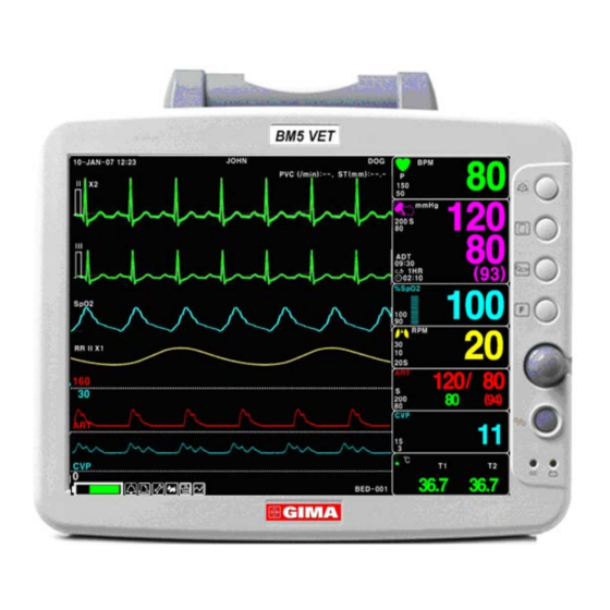
BM5VET User’s Manual 1.7 General Manu Operation Screen Composition Real Time Wave Parameter Window Windows JOHN 10- JA N- 07 12:23 B PM PVC ( / m i n ) - - , ST ( m m ) - - .-... -
Page 34: Menu Selection
BM5VET User’s Manual Menu Selection Turn or press the knob. When the Trim Knob Key is turned, menus are selected in the order indicated above. The above screen shows that the MORE menus is selected. The menus move to the right in the order of MORE MENU →... - Page 35 BM5VET User’s Manual Numerical value sign widow This window displays a measured parameter, function setup, and the boundary of parameter values. Breathing Alarm limit rate value Menu selection by using Trim Knob key As the key is turn to the right, the menu selection moves clockwise. As the key is turn to the left, the menu selection moves counterclockwise.
- Page 36 BM5VET User’s Manual > MAIN VOLUME : MENU PREV 100% MENU Word feature menu The following figure shows the screen where the word sequence menu is activated within the word sequence correction menu. Here, the cursor moves over the words when the Trim Knob key is turned in the clockwise direction.
- Page 37 BM5VET User’s Manual Operation menu The setup value changes without a selection when the menu is moved. ADMIT CHANGE MAIN TYPE : ADMIT ADMIT MENU INFO HEIGHT WEIGHT PREV UNIT: UNIT: MENU Rev. 2.0 1.BASIC 36...
-
Page 38: Patient/Data Management
BM5VET User Manual 2. PATIENT/DATA MANAGEMENT 2.1 ADMIT CHANGE ADMIT INFO DISCHARGE HEIGHT WEIGHT 2.2 ALARM ALL LIMITS ALARM PRINT ALARM VOLUME ALARM LEVEL ARRHYTH LEVEL ALARM REVIEW ALARM LIST SAVE ALARM LEVEL NURSE CALL Rev. 2.0 2.PATIENT/DATA MANAGEMENT 37... -
Page 39: Admit
BM5VET User’s Manual 2.1 ADMIT CHANGE ANIMAL INFO ANIMAL TYPE HEIGHT UNIT WEIGHT UNIT DEFAULTS SETTING ANIMAL TYPE You can select animal type as follow. HORSE : LARGE ANIMAL // DOG: MEDIUM ANIMAL PUPPY : SMALL ANIMAL // CAT : TINY ANIMAL Rev. -
Page 40: Change Animal Information
BM5VET User’s Manual CHANGE ANIMAL INFORMATION Hospital ID(11 letters for each), animal name (11 letters for each), sex (male or female), date of birth, weight, height, and animal ID (11 characters) DEFAULTS SETTING Animal information and all Alarm limits change to standard. -
Page 41: Height
BM5VET User’s Manual HEIGHT Unit of height is set as Cm / Inch. WEIGHT Unit of weight is set as Kg / LBS. Rev. 2.0 2.PATIENT/DATA MANAGEMENT... -
Page 42: Alarm
BM5VET User’s Manual 2.2 ALARM Alarm is divided into two, alarm for the patient’s condition and for the product’s condition. The patient’s alarm sounds when the diagnostic functions (ASYSTOLE, VTAC/VFIB, and VTAC) are detected. Each alarm sound differs in order and volume according to the levels of HIGH, MEDIUM, LOW and MESSAGE. -
Page 43: Alarm For The Product
BM5VET User’s Manual Alarm for the Product The machine gives alarm sounds for its system with a related message flashing. ≡ Alarm Text ≡ ALARM LIMITS:The machine enables one to see and change the limits of alarm for all parameter functions. -
Page 44: All Limits
BM5VET User’s Manual ALL LIMITS ALARM LEVEL ON/OFF ALL LIMITS MEDIUM UNITS HIGH RETURN LIMITS HIGH PARA MEDIUM TEMP2 °F 96.8 104.0 IBP1-S mmHg SPO2-% IBP1-M mmHg SPO2-R MEDIUM RESP mmHg IBP1-D mmHg RESP-A IBP1-PR mmHg IBP2-S NIBP-S mmHg MESSAGE... -
Page 45: Alarm Volume
BM5VET User’s Manual ALARM VOLUME Set the alarm volume to be set at 10 grades. ALARM > MAIN VOLUME: MENU PREV 100% MENU ALARM LEVEL Set the order of priority in each alarm. Rev. 2.0 2.PATIENT/DATA MANAGEMENT... -
Page 46: Parameter Level
BM5VET User’s Manual PARAMETER LEVEL ARRHYTH LEVEL One can set up priorities when he or she uses the alarm for the diagnostic function. Rev. 2.0 2.PATIENT/DATA MANAGEMENT... -
Page 47: Alarm Review
BM5VET User’s Manual ALARM REVIEW After an alarm is triggered the alarms and data wave pattern can be reviewed. Set up for priority of each parameter alarm. SAVE MAIN ALARM CONDITION : MENU LIST HIGH PREV MENU ALARM LIST When an alarm activates, this shows the order of the alarms. - Page 48 BM5VET User’s Manual SAVE MAIN ALARM CONDITION : MENU LIST HIGH PREV MENU Rev. 2.0 2.PATIENT/DATA MANAGEMENT...
-
Page 49: Save Condition
BM5VET User’s Manual SAVE CONDITION This determines the order in which triggered alarms are saved. Rev. 2.0 2.PATIENT/DATA MANAGEMENT... -
Page 50: Nurse Call
BM5VET User’s Manual NURSE CALL When an alarm is triggered, this activated the NURSE CALL function. ALARM ALARM MAIN PRINT: VOLUME: MENU LIMITS NURSE PREV ALARM ALARM CALL: MENU LEVEL REVIEW Rev. 2.0 2.PATIENT/DATA MANAGEMENT... -
Page 51: Setup
BM5VET User Manual 3. SETUP 3.1 SETUP DISPLAY DEMO USER SERVICE MAKER SERVICE Rev. 2.0 3.SETUP 50... -
Page 52: Setup
BM5VET User Manual 3.1 SETUP DISPLAY : screen set menu USER SERVICE : This is the menu to set the connection used to interface with an external computer MAKER SERVICE : This is the basic adjustment menu used to adjust the features of this product. -
Page 53: Set Para
BM5VET User’s Manual SET PARA Select measurement function to use WAVE SELECT Select waveform to display in large parameter display. Rev. 2.0 3.SETUP... - Page 54 BM5VET User’s Manual WAVE MAIN SELECT: MENU PARA > SPO2 RESP SWEEP PREV SPEED: MENU 25mm/s * The large parameter display at the selection of SpO2 Rev. 2.0 3.SETUP...
- Page 55 BM5VET User’s Manual * The large parameter display at the selection of RESP JOHN 10- JA N- 2008 12:23 30/ 10 B PM 150/ 50 m m Hg A DT 100/ 90 %Sp O2 42.0 30.0 09:58 42.0 30.0 0:56...
-
Page 56: Set Date & Time
BM5VET User’s Manual JOHN 10- JA N- 2008 12:23 30/ 10 B PM m m Hg 150/ 50 A DT 100/ 90 %Sp O2 42.0 30.0 09:58 42.0 30.0 0:56 A RT PVC ( / m i n ) :- , ST( m m ) : 0.0... -
Page 57: Set Time
BM5VET User’s Manual SET TIME Set time of equipment. MAIN MENU TIME: 10:58:01 PREV MENU SET DATE Set date of equipment MAIN MENU DATE: 06-MAR-2007 PREV MENU Rev. 2.0 3.SETUP... -
Page 58: Source
BM5VET User’s Manual HR SOURCE This menu is used to set the source that detects heart and pulse rate. The source can select among ECG and SPO2. SWEEP SPEED Set speed of drawing wave signal pattern in this widow. Rev. 2.0... -
Page 59: Demo
BM5VET User’s Manual DEMO Set ON/OFF DEMONSTRATION of equipment. MAIN USER DISPLAY MENU SERVICE PREV DEMO: MAKER SOUND: MENU SERVICE USER SERVICE The user is able to set the communication parameters, power supply filter, and patient’s age. SET UNIT NAME Set up for Equipment name. -
Page 60: Set Bed Number
BM5VET User’s Manual MAIN UNIT MENU NAME █ PREV MENU SET BED NUMBER Set up for patient bed number. Allowable setters are from 0~ 9, A ~ Z . AC FILTER AC FILTER is function where you can set power supply frequency. This feature is required because power supply frequency can be different from one country to another. -
Page 61: System
BM5VET User’s Manual SYSTEM System able to change and verify Equipment version information and system information MAKER SERVICE Maker service is a menu is used by manufacturers. Rev. 2.0 3.SETUP... -
Page 62: Trend
BM5VET User Manual 4. TREND 4.1 TREND GRAPHIC TREND TABLE TREND TREND WINDOW SETUP Rev. 2.0 4.TREND 61... -
Page 63: Trend
BM5VET User’s Manual 4.1 TREND TREND shows saved data graphically displayed with numeric values. Real-time data recording duration is 1 minute. Amount of saving time is for this data will be saving for 128hours. TREND MAIN GRAPHIC TABULAR WINDOW MENU... -
Page 64: Graphic Trend
BM5VET User’s Manual GRAPHIC TREND Wave Data can be stored and seen according to section. TREND MAIN GRAPHIC TABULAR WINDOW MENU TREND TREND SETUP PREV MENU Jo h n 10- JA N- 2007 12:23 B PM B PM PVC( / m i n ) : - - ,... -
Page 65: Time Period
BM5VET User’s Manual TIME PERIOD One can set up and store data and time that one can see in a screen. Jo h n 10- JA N- 2007 12:23 B PM B PM PVC( / m i n ) : - - ,... - Page 66 BM5VET User’s Manual TABULAR TREND One can see the stored data at the time previously set up. TREND MAIN GRAPHIC TABULAR WINDOW MENU TREND TREND SETUP PREV MENU Rev. 2.0 4.TREND 65...
-
Page 67: Time Interval
BM5VET User’s Manual TIME INTERVAL One can store data and set up time. TREND WINDOW SETUP Set the trend display window that will show the real time wave window. Rev. 2.0 4.TREND 66... -
Page 68: Time Period
BM5VET User’s Manual B PM 10-JAN-2007 12:23 B PM PVC (0/min): 0 ST(mm): II x2 m m Hg m m Hg ST/PVC 20. 0 20.0 MEDI 09:30 - 20.0 - 20.0 MEDI. 02:10 NBP/BP NIBP %Sp O2 %Sp O2 09:30... -
Page 69: Trend Print
BM5VET User’s Manual TIME MAIN SET TREND PERIOD: MENU PARA 30MINS PREV MENU TREND PRINT Graphic: select the number which selects a graphic trend and press print to prints the selected trend. Table: select the table number to be print and press print to receive print all the data in the selected patient admit (Admit) table. -
Page 70: Ecg
BM5VET User Manual 5. ECG 5.1 Outline Color and Name for Each Cable Size ECG Connector Location and Measurement Cable 5 Lead Electrode Attached Location 3 Lead Electrode Attached Location Method to Attach Electrode to Baby 5.2 ECG Data Window 5.3 ECG Data Setup... -
Page 71: Introduction
BM5VET User’s Manual 5.1 Introduction It calculates the heart rate with 3 or 5 leads ECG signal acquisition and perform the alarm according to the setting value. Colors and Standards of Cables Leadwire Color code Label Color code Label Right arm... -
Page 72: Attaching Electrodes To The Animal
BM5VET User’s Manual Attaching Electrodes to the Animal 1. Shave excess hair. With a piece of cotton pad moistened with alcohol, clean the animal’s skin where the electrodes should be mounted. Avoid wrinkled or uneven skin areas. Wipe off the alcohol with a dry cotton pad. -
Page 73: Choosing An Ecg Lead For Arrhythmia Monitoring
BM5VET User’s Manual Choosing an ECG lead for Arrhythmia Monitoring It is very important to select a suitable lead for arrhythmia monitoring. Guidelines for non-paced animals: QRS should be tall and narrow(recommended amplitude > 0.5mV) R wave should be above or below the baseline (but not bi-phasic) T wave should be smaller than 1/3 R-wave height. -
Page 74: Position Of 3-Lead Wire Electrode
BM5VET User’s Manual Position of 3-Lead Wire Electrode Rev. 2.0 5.ECG... -
Page 75: Position Of 5-Lead Wire Electrode
BM5VET User’s Manual Position of 5-Lead Wire Electrode Rev. 2.0 5.ECG... -
Page 76: Ecg Data Window
BM5VET User’s Manual 5.2 ECG Data Window Pace Detector QRS: Detects QRS, and Indicators: flashes when QRS is Detects and displays detected. the patient’s pace maker and flashes. Heart Rate Alarm Limit: Decides the QRS limits, and Heart Rate: gives an alarm if a value is over Displays heart rate per minute. - Page 77 BM5VET User’s Manual Safety Precautions Warning CABLES — Route all cables away from patient's throat to avoid possible strangulation. CONDUCTIVE CONNECTIONS — Extreme care must be exercised when applying medical electrical equipment. Many parts of the human/machine circuit are conductive, such as the patient, connectors, electrodes, transducers.
- Page 78 BM5VET User’s Manual INTERFACING OTHER EQUIPMENT — Devices may only be interconnected with each other or to parts of the system when it has been determined by qualified biomedical engineering personnel that there is no danger to the patient, the operator, or the environment as a result. In...
-
Page 79: Ecg Data Setup
BM5VET User’s Manual 5.3 ECG Data Setup A setup window appears at lower part of the screen when the Trim Knob Key is pressed in the ECG Parameter Window. Selection is made by pressing the Trim Knob Key, while movement across the menu is performed by turning the key either clock or anticlockwise. - Page 80 BM5VET User’s Manual LEAD 1 SELECT MENU LEAD MAIN SELECT : > MENU PREV MENU LEAD 2 SELECT MENU Rev. 2.0 5.ECG...
- Page 81 BM5VET User’s Manual LEAD 3 SELECT MENU LEAD MAIN SELECT : MENU > PREV MENU 3 traces are displayed at once in case of connecting 5-Leads ECG cable and IBP para OFF 3 difference traces are displayed in case of selecting all 3 traces in LEAD SELECT menu.
- Page 82 BM5VET User’s Manual Two different traces are displayed in case of selecting only 2 traces in LEAD SELECT menu. The two traces of one lead are displayed in case of selecting only one lead in LEAD SELECT menu. Rev. 2.0...
-
Page 83: Alarm Limit
BM5VET User’s Manual ALARM LIMIT Alarm Limit is 0 ~ 350. LEAD MAIN SELECT : ALARM MENU PREV ANALYSIS QRS VOLUME : DISPLAY MENU SETTING Rev. 2.0 5.ECG... -
Page 84: Alarm Sound
BM5VET User’s Manual ALARM SOUND Set ON/OFF of ECG alarm sound. MAIN LEAD ALARM MENU SELECT PREV ANALYSIS DISPLAY VOLUME : MENU SETTING QRS VOLUME Move the Key to select a volume rate from OFF, 10% to 100%. Rev. 2.0... -
Page 85: Display
BM5VET User’s Manual > MAIN VOLUME : MENU PREV 100% MENU DISPLAY Set the sweep speed and waveform size. ECG SWEEP SPEED ECG speed is 25 mm/s. Speed is changeable to 6.25, 12.5, 25, 50mm/s. Rev. 2.0 5.ECG... -
Page 86: Ecg Size
BM5VET User’s Manual ECG SIZE The size is changeable to X0.25, X0.5, X1, X2, X4. SWEEP MAIN SOURCE: SPEED : SIZE : MENU 25 mm/s 7CHANNEL PREV VIEW MENU :OFF HR SOURCE SWEEP MAIN SOURCE: SPEED : MENU 25 mm/s >... -
Page 87: 7Channel View
BM5VET User’s Manual 7CHANNEL VIEW Set 7Ch ECG View mode. ECG traces are only displayed when 7CHANNEL VIEW is ‘On’. SWEEP MAIN SPEED : SIZE : SOURCE: MENU 25 mm/s 7CHANNEL PREV VIEW MENU SWEEP MAIN SOURCE: SPEED : SIZE :... -
Page 88: Analysis Setting
BM5VET User’s Manual ANALYSIS SETTING Analysis setting is divided to 3 menus. ECG FILTER:One may select from three frequency types for WAVE FILTER. MONITOR 0.5Hz ~ 40Hz MODERATE 0.5Hz ~ 25Hz MAXIMUM 5Hz ~ 25Hz DIAGONOSIS 0.05Hz ~ 120Hz Rev. 2.0... - Page 89 BM5VET User’s Manual MAIN PACE : ARRHYTHM : FILTER : MENU MONITOR PREV PVC SETTING ST SETTING MENU PACE:Sets up ON/OFF to indicate that the patient has PACE. The PACE menu option enables/disables the pacemaker detection program. Be aware of the following when monitoring a patient with a pacemaker.
- Page 90 BM5VET User’s Manual . Rate meters may continue to count the pacemaker rate during occurrences PACEMAKER PATIENTS of cardiac arrest or some arrhythmias. Do not rely entirely upon rate meter . Keep pacemaker patients under close surveillance. ALARMS ARRHYTH: Sets up ON/OFF to indicate detection of diagnosis (Asys, VTAC/VFIB and VTAC).
- Page 91 BM5VET User’s Manual Occurs when two or more bigeminal cycles (a ventricular beat followed by a non-ventricular beat) are detected. BRADY Bradycardia is the average of the most recent eight R-to-R intervals at a heart rate less than the set low heart rate limit.
- Page 92 BM5VET User’s Manual TRIGEMINY Occurs when two or more trigeminal cycles (a ventricular beat followed by two non- Ventricular beats) are detected. V BRADY Adult—Ventricular bradycardia occurs when a run of three or more ventricular beats is detected with an average heart rate that is less than or equal to 50 beats per minute.
- Page 93 BM5VET User’s Manual MEASUREMENT CONDITION: ST measurement condition setting MAIN MEASUREMENT ANALYSIS : MENU CONDITION ALARM LIMIT TEMPLETE PREV SELECT: MENU ALARM LEVEL Rev. 2.0 5.ECG...
- Page 94 BM5VET User’s Manual ST ALARM LIMIT: ST alarm limit range setting MAIN MEASUREMENT ANALYSIS : MENU CONDITION ALARM LIMIT TEMPLETE PREV SELECT: MENU ALARM LEVEL Rev. 2.0 5.ECG...
- Page 95 BM5VET User’s Manual ST ALARM LEVEL: ALARM LEVEL setting MAIN MEASUREMENT ANALYSIS : MENU CONDITION ALARM LIMIT TEMPLETE PREV SELECT: MENU ALARM LEVEL Rev. 2.0 5.ECG...
- Page 96 BM5VET User’s Manual TEMPLETE SELECT: Select a Representative Lead of ST LEVEL. The trace of the selected LEAD shows up at ST Window of POPUP TREND WINDOW MAIN MEASUREMENT ANALYSIS : MENU CONDITION ALARM LIMIT TEMPLETE PREV SELECT: MENU ALARM LEVEL...
- Page 97 BM5VET User’s Manual PVC ALARM LIMIT: Set alarm indicate to PVC PVC ALARM LEVEL: Set PVC ALARM LEVEL Rev. 2.0 5.ECG...
- Page 98 BM5VET User’s Manual Warning Display Hart Beat Equipment Signal Hart Beat equipment signal displays when the PACE mode is. the signal appears series form. The signal size or form are meaningless clinically Number Of Heart Beat Attention to the patient with heart beat equipment. The heart beat equipment can show heart beat even during arrhythmia continuously.
- Page 99 BM5VET User Manual CAUTION FDA POSTMARKET SAFETY ALERT The United States FDA Center for Device and Radiological Health issued a safety bulletin October 14, 1998. this bulletin states “that minute ventilation rate-adaptive implantable pacemakers can occasionally interact with certain cardiac monitoring and diagnostic programmed rate.”...
- Page 100 BM5VET User’s Manual WARNINGS VENTRICULAR ARRHYTHMISAS The arrhythmia analysis program is intended to detect ventricular arrhythmias. It is not designed to detect a trial or supra ventricular arrhythmias. Occasionally it may incorrect identify the presence or absence of an arrhythmia. Therefore, a physician must analyze the arrhythmia information in conjunction with other clinical findings.
- Page 101 BM5VET User’s Manual Problem : False ventricular calls. Solution : Check ECG signal from patient: (the chest lead may exhibit polarity changes which may occasionally cause an inaccurate call.) 1. Check/adjust lead placement. 2. Check/perform skin preparation. 3. Check/replace electrodes. (if chest lead is a problem, move the chest lead to another chest position or leg position.)
-
Page 102: Spo2
BM5VET User Manual 6. SpO 6.1 Outline Connector Location and Measuring Cable 6.2 SpO2 Data Window 6.3 SpO2 Data Setup SWEEP SPEED RATE VOLUME ALARM ALARM LIMIT Rev. 2.0 6.SpO2 101... -
Page 103: Outline
BM5VET User’s Manual 6.1 Outline SPO2 monitoring is a noninvasive technique used to measure the amount of oxygenated hemoglobin and pulse rate by measuring the absorption of selected wavelengths of light. The light generated in the probe passes through the tissue and is converted into an electrical signal by the photodetector in the probe. - Page 104 BM5VET User’s Manual Position of SpO Probe Note The signal input is a high-insulation port and it is defibrillator proof ( The insulated input ensures patient safety and protects the device during defibrillation and electrosurgery. Rev. 2.0 6.SpO2 103...
-
Page 105: Spo2 Data Window
BM5VET User’s Manual 6.2 SpO Data Window Alarm Limit: Indicates an SpO alarm limit %SpO2 Oxygen Concentration in the Strength indicators: Blood(SpO2 value) Indicates SpO Strength in a bar : Indicates %SpO in numbers. graph. The current SPO2 value and the derived pulse rate (RATE) are displayed. The block sets indicate the strength of the signal (twenty block bars indicate the strongest signal). -
Page 106: Signal And Data Validity
BM5VET User’s Manual Signal and Data Validity It is extremely important to determine that the probe is attached to the patient correctly and the data is verifiable. To make this determination, three indications from the monitor are of assistance—signal strength bar, quality of the SPO2 waveform, and the stability of the SPO2 values. It is critical to observe all three indications simultaneously when ascertaining signal and data validity. - Page 107 BM5VET User’s Manual Stability of SPO2 Values The stability of the displayed SPO2 values can also be used as an indication of signal validity. Although stability is a relative term, with a small amount of practice one can get a good feeling for changes that are artifactual or physiological and the speed of each.
-
Page 108: Spo Data Setup
BM5VET User’s Manual 6.3 SpO Data Setup ALARM : Menu in which SpO alarm are set up. RATE VOLUME:Menu in which RATE VOLUME is set up RATE MAIN ALARM VOLUME: MENU RATE VOLUME Move the KEY to select the volume from OFF to 100%. -
Page 109: Alarm
BM5VET User’s Manual ALARM Two menus: ALARM LIMIT, ALARM SOUND provided in the alarm menu RATE MAIN ALARM VOLUME: MENU ALARM LIMIT Number setting of alarm value of %SpO 0 ~ 100 2 is 1. Move the mark to select from RETURN, SpO or SpO -R, and press. -
Page 110: Alarm Sound
BM5VET User’s Manual ALARM SOUND Warning sound or message displays configuration menu when an alarm is triggered. LEAD FAULT Condition When using a reusable finger probe, there is a system alarm to alert you when the probe is off the Monitor. -
Page 111: Spo2 Messages
BM5VET User’s Manual SPO2 Messages Below is a list of system status alarm messages which may be displayed in the SPO2 parameter window during monitoring. CHECK PROBE Reusable finger probe is off the patient. Check the probe. The factory default for this alarm is MESSAGE ALARM. -
Page 112: Respiration
BM5VET User Manual 7. RESPIRATION 7.1 Outline Respiration Connector and Measuring Cable 7.2 RESPIRATION Data Window 7.3 RESPIRATION Data Setup Respiration Size Alarm Limit Rev. 2.0 7.RESPIRATION 111... -
Page 113: Outline
BM5VET User Manual 7.1 Outline Respiration via ECG Lead II electrode makes the skin area of the chest enlarged, causing changes in the resistance of skin. Through this it calculates respiration value per minute and performs the alarm function according to limit value. -
Page 114: Respiration Data Window
BM5VET User’s Manual 7.2 Respiration Data Window Breathe indicator: Indicates the detected breath Apnea Limit Setting: Apnea limit sign Respiration alarm limit: Indicates respiration limits. Breathing Number: Displays the number of respiration per minute. Rev. 2.0 7.RESPIRATION 113... -
Page 115: Respiration Data Setup
BM5VET User’s Manual 7.3 Respiration Data Setup ALARM: Respiration alarm setting menu RESP SIZE: A menu to setup Wave Display SWEEP SPEED: A menu to setup Wave Display of speed APNEA DETECT: A menu to setup APNEA alarm display SWEEP... -
Page 116: Respiration
BM5VET User’s Manual RESPIRATION Set wave pattern size X2~ X10. SWEEP RESP MAIN ALARM SPEED : SIZE : MENU 12.5mm/s APNEA LEAD SELECT: DETECT : APNEA DETECT Deciding function of activating Apnea Alarm SWEEP RESP MAIN ALARM SPEED : SIZE : MENU 12.5mm/s... -
Page 117: Alarm
BM5VET User’s Manual SWEEP RESP MAIN ALARM SPEED : SIZE : MENU 25mm/s APNEA LEAD SELECT: DETECT : ALARM Alarm menu provide ALARM LIMIT and ALARM SOUND . ALARM LIMIT Alarm Limit of Respiration Numeric Value is 5 ~ 150bpm Alarm Limit of RESPIRATION APNEA Numeric Value is 3 ~ 30sec. -
Page 118: Alarm Sound
BM5VET User’s Manual ALARM MAIN ALARM SOUND : MENU LIMIT PREV MENU 1. Move the mark to select RETURN, RESP or RESP-A, and press. 2. After a press in RESP, move the cursor right or left to LOW, and press. - Page 119 BM5VET User’s Manual ALARM MAIN ALARM SOUND : MENU LIMIT PREV MENU Rev. 2.0 7.RESPIRATION 118...
-
Page 120: Nibp
BM5VET User Manual 8. NIBP 8.1 Outline NIBP Connector Location and Cuff 8.2 NIBP Data Window 8.3 NIBP Data Setup ALARM LIMIT ALARM CUFF SIZE UNIT SELECT INTERVAL STAT INFLATION Rev. 2.0 8.NIBP... -
Page 121: Outline
BM5VET User’s Manual 8.1 Outline This function is to measure minimum, Maximum and average blood pressure by using Oscillometric method Position of NIBP Connecter and cuff NIBP Connector LARGE CUFF Rev. 2.0 8. NIBP 120... - Page 122 BM5VET User’s Manual CAT CUFF Placement DOG CUFF Placement Note As the value of NIBP can vary according to the age and sex of a patient, the user needs to set up right data in Parameter Menu before measurement. WARNING Noninvasive blood pressure monitoring is not recommended for patients with hypotension, hypertension, arrhythmias or extremely high or low heart rate.
- Page 123 BM5VET User’s Manual Note As the value of NIBP can vary according to the age and sex of a animal, the user needs to set up right data in parameter Menu before measurement. Tubes between the cuff and the monitor are not kinked or blocked.
-
Page 124: Nibp Data Window
BM5VET User’s Manual 8.2 NIBP Data Window Alarm Limit:Indicates alarm limit of blood pressure. Systolic pressure: Indicates the maximum limit of blood pressure mmHg Diastolic blood pressure:Indicates 09:30 1 HR the minimum limit of (93) Measurement time 0:54 blood pressure... -
Page 125: Nibp Data Setup
BM5VET User’s Manual 8.3 NIBP Data Setup ALARM: A menu to set the Alarm CUFF SIZE:A menu to select cuff size UNIT SELECT: A menu to select the pressure unit INTERVAL :A menu to set Interval time when measures the blood pressure periodically... -
Page 126: Alarm Sound
BM5VET User’s Manual 2. Press the key at NIBP-S, and move to LOW, and press again.(The user gets the same result regardless of the LOW-HIGH, or HIGH-LOW order.) 3. When the color has changed, move it again to select a target value, and press. -
Page 127: Cuff Size
BM5VET User’s Manual ALARM MAIN ALARM SOUND: MENU LIMIT PREV MENU CUFF SIZE The user can select a CUF between ADULT and NEONATAL. CUFF MAIN ALARM SIZE: MENU MEDIUM UNIT INFLATION: INTERVAL: SELECT: 170mmHg mmHg MAIN CUFF ALARM MENU SIZE: >... -
Page 128: Interval
BM5VET User’s Manual CUFF MAIN ALARM SIZE: MENU MEDIUM UNIT INFLATION: INTERVAL: SELECT: 170mmHg INTERVAL This menu is used for selecting intervals when measures the blood pressure automatically. Select a target interval from 1min, 2, 3, 4, 5, 10, 15, 20, 30, 1hour, 2, 4, 8. - Page 129 BM5VET User’s Manual CUFF MAIN ALARM SIZE: MENU MEDIUM UNIT INFLATION: INTERVAL: SELECT: 80mmHg mmHg CUFF MAIN ALARM SIZE: MENU MEDIUM UNIT INFLATION: INTERVAL: SELECT: 240mmHg mmHg Warning Pay attention to not to block connecting hose when you put cuff on patient.
-
Page 130: Ibp
BM5VET User Manual 9. IBP 9.1 Description IBP Connectors & Accessories 9.2 IBP Data Window 9.3 IBP Data Setting CHANGE NAME (Configuration of measuring position) SCALE (Configuring size of measurement waveform) ALARM LIMITS (Maximum / Minimum Alarming Values) SETTINGS (Various Settings) ZERO (Zero-Point Setting) Rev 2.0... -
Page 131: Description
BM5VET User’s Manual 9.1 Description IBP has an alarming function based on the maximum & minimum alarming values configured by measuring the systolic, diastolic and mean blood pressure values with signal processing of electric signals which are transformed from changes in impedance components according to the changes of blood flow in vessels. - Page 132 BM5VET User’s Manual TranStar Disposable Pressure Transducers Cartridges and Monitoring kit Rev 2.0 9. IBP 131...
- Page 133 BM5VET User’s Manual Rev 2.0 9. IBP 132...
-
Page 134: Ibp Data Window
BM5VET User Manual 9.2 IBP Data Window Different data windows are displayed on the screen according to the measuring positions. Measuring Position: Position of blood pressure measurement Systolic Blood Pressure: Indicating maximum blood pressure value Diastolic Blood Pressure: Indicating minimum blood pressure value... -
Page 135: Ibp Data Setting
BM5VET User Manual 9.3 IBP Data Setting Labels for measuring positions are described on each menu. CHANGE NAME: Menu to set measuring position SCALE: Menu to set size of measurement waveform on screen. LIMITS: Menu to set alarming range. SETTING: Menu for processing various pressure signals. - Page 136 BM5VET User Manual List & Description of IBP Measurement Parameter Label Parameter Window, Scales Menu Window or Alarm Limits Pop-up Menu will appear according to the Labels. IBP displays the measuring positions based on 10 labels shown in the below table.
- Page 137 BM5VET User’s Manual Alarming Limits for ART Alarming limits vary according to measuring positions. The settable alarming range for systolic pressure, diastolic pressure and mean pressure is - 50 ~ 350mmHg. CHANGE MAIN ALARM NAME SCALE: MENU LIMIT :ART UNIT...
- Page 138 BM5VET User’s Manual The below table shows the settable values of standard alarm limits and scales of parameters for label setting. Adult Neonatal Parameter High Scale High Scale ART-S ART-D ART-M ART-PR FEM-S FEM-D FEM-M FEM-PR UAP-S UAP-D UAP-M UAP-PR...
- Page 139 BM5VET User’s Manual BP1(BP2)-M BP1(BP2)-PR IBP SETTING (Setting Various Functions) Other menus are to be applied for special functions to process pressure signals in various ways. Setting three labels of ART, FEM and UAP displaying PULSE-RATE among labels, the functions of PULSE-RATE DISPLAY and DISCONNECT ALARM will be added.
- Page 140 BM5VET User’s Manual PULSE RATE: Setting display of blood pressure pulse rate. PULSE MAIN FILTER: RATE: MENU DISCONN. PREV ALARM: MENU PULSE MAIN FILTER: RATE: MENU DISCONN. PREV ALARM: MENU CAL. TRANSDUC: A function to adjust a Transducer error on the monitor.
- Page 141 BM5VET User’s Manual 3. Compare the measured values of ‘mmHg’ for both manometers. 4. Adjust the error value on the parameter menu screen by turning knob switch. 5. Terminate the menu by pressing the knob switch key again. DISCONN ALARM: (Alarming function for disconnection) DISCONN ALARM MENU will be displayed when measurement label is set for ART, FEM and UAP.
- Page 142 BM5VET User’s Manual In case of using blood pressure transducer Check position of transducer with a different sensitivity For other cases Perform zero-point adjustment ZERO ART: (Zero-point Adjustment) Use ZERO option to set the zero-point of Transducer. Procedures (Zero reference) 1) Close the transducer stopcock on the patient’s side.
- Page 143 BM5VET User’s Manual Warning All parts, except Transducer, should not be conductive. Otherwise discharge energy may induce a shock to operators during cardioversion. Note Check if there is a scratch on the catheter balloon before using. Do not reuse disposal parts and accessories.
-
Page 144: Etco2
BM5VET User Manual 10. EtCO2 10.1 INTRODUCTION Position of EtCO Connector and Accessory EtCO ACCESSORY 10.2 EtCO Parameter Window 10.3 EtCO Parameter Setting Menu Rev 2.0 10.EtCO2 143... -
Page 145: Introduction
BM5VET User Manual 10.1 Introduction ETCO2(End-Tidal CO2) is a device to see the concentration of end-tidal carbon dioxide, which uses a method of measurement based on the non-dispersed IR absorption of CO2 using IR ray by sampling a certain part of respiration through pipe during respiration. - Page 146 BM5VET User’s Manual EtCO2 accessories for sidestream applications EtCO2 monitoring accessory uses the accessories for LoFlo™ sidestream module of Respironics Company. The airway adapters for sidestream intubated applications 3473ADU-00 Airway Adapter Dog/Horse Kit w/ Weight: 4.5 grams Dehumidification Deadspace – adds approximately 7...
- Page 147 BM5VET User’s Manual 2. Inserting the sample cell into the receptacle automatically starts the sampling pump. Removal of the sample cell turns the sample pump off. 3. To remove the sampling kit sample cell from the sample cell receptacle, press down on the locking tab and pull the sample cell from the sample cell receptacle.
- Page 148 BM5VET User’s Manual EtCO2 connector position and accessory (Mainstream, Respironics) EtCO2 Connector CAPNOSTAT 5 mainstream CO2 sensor and connector Mainstream sensor Mainstream sensor connector EtCO2 accessories for mainstream applications EtCO2 monitoring accessory uses the accessories for CapnoStat 5 microstream sensor of Respironics Company.
- Page 149 BM5VET User’s Manual The airway adapters for mainstream intubated applications 6063-00 Single-Patient Use Horse Airway Adapter 6312-00 Single-Patient Use Cat and Puppy Airway Adapter 7007-00 Reusable Horse and Dog Airway Adapter 7053-00 Reusable Cat and Puppy Airway Adapter Connecting the CAPNOSTAT® 5 CO2 Sensor to the Host System 1.
- Page 150 BM5VET User’s Manual Shown below is the CAPNOSTAT 5 CO Sensor with a patient circuit: Rev 2.0 10.EtCO2 149...
-
Page 151: Etco2 Parameter Window
BM5VET User’s Manual 10.2 EtCO2 Parameter Window Upper/lower limit value of FiCO2 alarm S: Display of apnea setting time in second unit Upper/lower limit value of alarm: Display of alarm setting range value for concentration of CO EtCO : Display of concentration value of carbon dioxide... -
Page 152: Etco2 Parameter Setting Menu
BM5VET User’s Manual 10.3 EtCO2 Parameter Setting Menu ALARM LIMITS: A menu to set the alarm limit STANDBY: A menu to set the power saving status of EtCO2 module SCALE: A menu to set the screen scale of measured waveform... -
Page 153: Etco2 Sweep Speed
BM5VET User’s Manual The following table shows standard alarm limit of parameter and setting value of scale when setting the label. Adult Neonatal Parameter High Scale High Scale EtCO2 FiCO2 AWRR APNEA EtCO2 SWEEP SPEED EtCO2 speed is 6.5mm/s. Speed is changeable to 6.25, 12.5, 25mm/s. - Page 154 BM5VET User’s Manual WAVEFORM SCALE (Measured waveform scale setting) This sets the range of measured waveform versus pressure. Selectable numerical value means the maximum pressure range value that is shown with waveform. Pressing the knob switch key and then selecting the desired range value displays the selected pressure range value below the upper dotted line among two dotted lines in the left middle of wave window.
- Page 155 BM5VET User’s Manual MODULE INFO SET RETURN CONTENTS BAROMETRIC PRESSURE 760 mmHg GAS TEMPERATURE 0.0 ℃ NO BREATH DETECT TIMEOUT 0 SEC O2 COMPENSATION 21 % ANESTHETIC AGENT 0.0 % BALANCE GAS ROOM AIR CURRENT ETCO2 TIME PERIOD 0000-00-00-00 CURRENT CO2 UNIT...
- Page 156 BM5VET User’s Manual breaths. Continuous waveform mode commands (the CO Waveform CURRENT CO2 UNIT: Mode command [command 80h] and the CO Waveform Mode command [command 90h] ) MUST NOT be active when this command is used otherwise this command will be ignored and the setting will remain unchanged.
- Page 157 BM5VET User Manual Warning If defibrillation is performed while doing CO2 monitoring, remove the CO2 FilterLine from patient Getting in touch with sensor cable without removing the FilterLine can result in serious electrical burn, shock, or injury due to electric discharge energy.
-
Page 158: Temperature
BM5VET User Manual 11. TEMPERATURE 11.1 Outline Temperature Connector and Measuring Cable 11.2 Temperature Data Window 11.3 Temperature Data Setup ALARM LIMIT UNIT SELECT Rev. 2.0 11.TEMPERATURE 157... -
Page 159: Outline
BM5VET User Manual 11.1 Outline This function is used to indicate the changes of resistance generated by the changes of temperature in numbers. The function involves the process of transferring the changes into electric signals. Temperature Connector and Measuring Cable... -
Page 160: Temperature Data Window
BM5VET User’s Manual 11.2 Temperature Data Window Unit: Displays temperature unit. Temperature: Displays temperature. Alarm limit on the least low temperature : Indicates temperature limits Note The minimum measuring time required to obtain accurate readings at the specific body site is at least 3 minutes. -
Page 161: Temperature Data Setup
BM5VET User’s Manual 11.3 Temperature Data Setup ALARM: Temperature measurement alarm set UNIT: Temperature measurement unit set UNIT MAIN ALARM SELECT: MENU °C ALARM Alarm menu provide ALARM LIMIT and ALARM SOUND. Rev. 2.0 11.TEMPERATURE 160... -
Page 162: Alarm Limit
BM5VET User’s Manual ALARM LIMIT Setting numeric value is 15.0 ~ 45.0 . 1. Move the mark to select either RETURN or TEMP, and press. 2. After pressing the cursor at TEMP, move it to LOW, and press. 3. When the color has changed, move the cursor again to select a target value, and press. -
Page 163: Unit Select
BM5VET User’s Manual ALARM SOUND The menu which decide activate of warning sign and message display when the respiration alarm is ALARM MAIN ALARM SOUND : MENU LIMIT PREV MENU UNIT SELECT Able to select unit with °C, °F. Rev. 2.0... -
Page 164: Print
BM5VET User Manual 12. PRINT 12.1 Print Printer and Heat Sensitivity Paper Function and Setup Menu 12.2 Paper Change Rev. 2.0 12.PRINT... -
Page 165: Print
BM5VET User Manual 12.1 Print Printer and Heat Sensitivity Paper A printer used to print data onto thermal paper. Size of the thermal paper roll: 580mm wide x 380mm in diameter any thermal paper of same size can be used for the printer. -
Page 166: Function And Setup Menu
BM5VET User’s Manual Function and Setup Menu 1. Press the PRINT Key for continuous printing. 2. Select Printing Speed 25, 50 mm/s. PRINTER WAVE MAIN SPEED: FORM1: MENU 25mm/s WAVE WAVE PREV FORM3: FORM2: MENU SPO2 RESP PRINTER WAVE MAIN... - Page 167 BM5VET User’s Manual WAVE MAIN FORM1: MENU SPO2 > SPO2 RESP PREV MENU PRINTER WAVE MAIN SPEED: FORM1: MENU 50mm/s LEAD II WAVE WAVE PREV FORM3: FORM2: MENU SPO2 RESP If there is no print sheet, no paper icon of appears.
-
Page 168: Paper Change
BM5VET User’s Manual 12.2 Paper Change Open the window of the printer. Insert the paper roll offered with the product into the printing unit. Place the roll in a proper way so that the printed paper can roll out upwards. -
Page 169: Message List
BM5VET User Manual 13. MESSAGE LIST Function Message Details LEAD FAULT Cable is not properly attached patient. CABLE OFF Cable is not properly connected. LEAD FAULT Cable is not properly connected. CHECK PROBE Patient’s finger is off the probe. PULSE SEARCH Detection by the monitor of a pulse has ceased. -
Page 170: Factory Defaults
BM5VET User Manual 14. FACTORY DEFAULTS Alarm level (Horse) Alarm level (Dog) Alarm level (Cat and Puppy) Parameter Limits(Horse) Parameter Limits(Dog) Parameter Limits(Cat and Puppy) Rev 2.0 14.FACTORY DEFAULTS... -
Page 171: Alarm Level (Horse)
BM5VET User Manual Alarm level (Horse) High Medium Message Asystole ● Vfib/VTac ● V TAC ● ● NIBP ● IBP1 ● IBP2 ● ETCO2 ● FiCO2 ● ● -Rate ● ● RR-Apnea ● TEMP1(ْ C) ● TEMP2(ْ C) ● PVC/min ●... -
Page 172: Alarm Level (Dog)
BM5VET User’s Manual Alarm level (Dog) High Medium Message Asystole ● Vfib/VTac ● V TAC ● ● NIBP ● IBP1 ● IBP2 ● ETCO2 ● FiCO2 ● ● -Rate ● ● RR-Apnea ● TEMP1(ْ C) ● TEMP2(ْ C) ● PVC/min ●... -
Page 173: Alarm Level (Cat And Puppy)
BM5VET User’s Manual Alarm level (Cat and Puppy) High Medium Message Asystole ● Vfib/VTac ● V TAC ● ● NIBP ● IBP1 ● IBP2 ● ETCO2 ● FiCO2 ● ● -Rate ● ● RR-Apnea ● TEMP1(ْ C) ● TEMP2(ْ C) ●... -
Page 174: Parameter Limits(Horse)
BM5VET User’s Manual Parameter Limits(Horse) High NIBP-S NIBP-M NIBP-D -Rate RR(RESP) RR-Apnea TEMP1( ْ C/ْ F) 30.0/42.0 86.0/107.6 TEMP2( ْ C/ْ F) 30.0/42.0 86.0/107.6 IBP1-S IBP1-M IBP1-D IBP1-R IBP2-S IBP2-M IBP2-D IBP2-R ETCO2 FICO2 AWRR ETCO2-APNEA PVC/min -2.0 Rev. 2.0... -
Page 175: Parameter Limits(Dog)
BM5VET User’s Manual Parameter Limits(Dog) High NIBP-S NIBP-M NIBP-D -Rate RR(RESP) RR-Apnea TEMP1( ْ C/ْ F) 30.0/42.0 86.0/107.6 TEMP2( ْ C/ْ F) 30.0/42.0 86.0/107.6 IBP1-S IBP1-M IBP1-D IBP1-R IBP2-S IBP2-M IBP2-D IBP2-R ETCO2 FICO2 AWRR ETCO2-APNEA PVC/min -2.0 Rev. 2.0... -
Page 176: Parameter Limits(Cat And Puppy)
BM5VET User’s Manual Parameter Limits(Cat and Puppy) High NIBP-S NIBP-M NIBP-D -Rate RR(RESP) RR-Apnea TEMP1( ْ C/ْ F) 30.0/42.0 86.0/107.6 TEMP2( ْ C/ْ F) 30.0/42.0 86.0/107.6 IBP1-S IBP1-M IBP1-D IBP1-R IBP2-S IBP2-M IBP2-D IBP2-R ETCO2 FICO2 AWRR ETCO2-APNEA PVC/min -2.0 Rev. -
Page 177: Trouble Shooting
BM5VET User Manual 15. TROUBLE SHOOTING 15.1 Noise in ECG - Gel is dry - Electrodes does not stick well to skin The patient’s skin Apply ECG gel or water to the area of is extremely dry contact then use the electrode... -
Page 178: Spo2 Malfunction
BM5VET User’s Manual 15.2 SpO malfunction Connectors of the equipments are in bad condition? The extension cables are disconnected Replace extension cables The Finger probe is in bad condition? Replace the finger probe Repair the ECG B/D 15.3 Temp malfunction... -
Page 179: Nibp Malfunction
BM5VET User’s Manual 15.4 NIBP malfunction Are leaks from the hose connector of cuff Replace the hose of cuff Repair the NIBP B/D 15.5 Abnormality in NIBP measurements The patient moved Make sure the patient stay still while measuring during diagnosis... -
Page 180: Failure In Battery Recharge
BM5VET User’s Manual 15.6 Failure in battery recharge ( the battery does not fully recharge in 6 hours or more) Replace the adapter The output voltage of (the battery will not be changed at the rate lower than 17V) the adapter is 18V... -
Page 181: Power Failure
BM5VET User’s Manual 15.7 Power failure The adapter connector is in bad condition Replace the adapter The output voltage of the adapter is lower than 18V Replace the adapter Repair the power B/D Execute the “admit:” function “Admit” has been... -
Page 182: Periodic Noises
BM5VET User’s Manual 15.8 Periodic noises All alarm has been turned off Display lead fault Turn functions not in use off message appears (Mode-Display-Set para) The printer function abnormally Replace the printer Repair the accompanying Equipment Rev. 2.0 15. TROUBLE SHOOTING... -
Page 183: Print Failure
BM5VET User’s Manual 15.9 Print failure The paper tray cover is properly shut Shut the cover tight The printing face of paper has been reversed Reverse the paper face Repair the printer and printer B/D Rev. 2.0 15. TROUBLE SHOOTING... -
Page 184: Specification
BM5VET User Manual 16. SPECIFICATION Ease of use Customization Special Features Monitor Environmental Specifications Power adaptor Monitor Performance Specifications Graphical and Tabular Trends SpO2 Performance Specifications Respirations Performance Specifications NIBP Performance Specifications ECG Performance Specifications Temperature Unit Performance Specifications Accessories included OPTION Rev. -
Page 185: Ease Of Use
BM5VET User’s Manual Ease of use · Battery operation · Attached printer · Table and graphic trend Additional Function · Able to use auto mobile power supply · LAN Connection Monitor Environmental Specifications · Operating Temperature: 15°C to 40°C (59°F to 104°F) ·... - Page 186 BM5VET User’s Manual Heart Rate Range Adult : 30 – 300 bpm Neonate/Pediatric : 30 – 350 bpm Heart Rate Accuracy ±1bpm or ±1%, whichever is greater Sweep speed 6.25, 12.5, 25, 50 mm/sec Filter Diagnostic mode : 0.05Hz - 120Hz Monitoring mode : 0.5 –...
- Page 187 BM5VET User’s Manual Accuracy <100mmHg : ±1mmHg >=100mmHg : ±1% of reading Pulse rate measurement 0 to 300bpm range Zero balancing Range : ±200mmHg Accuracy : ±1mmHg Drift : ±1mmHg over 24hours Transducer sensitivity 5µV/mmHg Pulse rate measurement 0 to 300bpm...
-
Page 188: Accessories Included
BM5VET User’s Manual Accessories Included: 1. Main body of BM5VET Monitor 1 EA 2. 3-Lead Patient Cable (3CBL-400, 3WIRE-430) 1 EA 3. NIBP extension tube (3m, NBPCBL-400) 1 EA 4. Reusable NIBP cuff (25-35 cm, ACUFF-430) 1 EA 5. SpO... -
Page 189: Abbreviations And Symbols
BM5VET User Manual Abbreviations and Symbols Abbreviations and symbols which you may encounter while reading this manual or using the monitor are listed below with their meanings. Abbreviations amps alternating current adult ARRYTHM arrhythmia ASYS asystole Auto, AUTO automatic Auxiliary... - Page 190 BM5VET User’s Manual kg, KG kilogram kilopascal liter, left left arm, left atrial pounds liquid crystal display light emitting diode left leg M mean, minute meter MIN, min minute MM, mm millimeters MM/S millimeters per second MMHG, mmHg millimeters of mercury...
- Page 191 BM5VET User’s Manual VTAC ventricular tachycardia multiplier when used with a number (2X) Symbols & ° degree(s) > greater than < less than – minus number percent ± plus or minus Rev. 2.0 Abbreviations and Symbols...
-
Page 192: Product Warranty
Phone : Sales Agency Manufacturer * Thank you for purchasing BM5VET. * The product is manufactured and passed through strict quality control and through inspection. * Compensation standard concerning repair, replacement, refund of the product complies with “Consumer’s Protection Law” noticed by Economic Planning Dept. - Page 193 The warranty is valid for 12 months from the date of supply of GIMA. During the period of validity of the warranty, GIMA will repair and/or replace free of charge all the defected parts due to production reasons. Labor costs and personnel traveling expenses and packaging not included.
Need help?
Do you have a question about the BM5VET and is the answer not in the manual?
Questions and answers