
Related Manuals for Gima Rescue LIFE


Summary of Contents for Gima Rescue LIFE
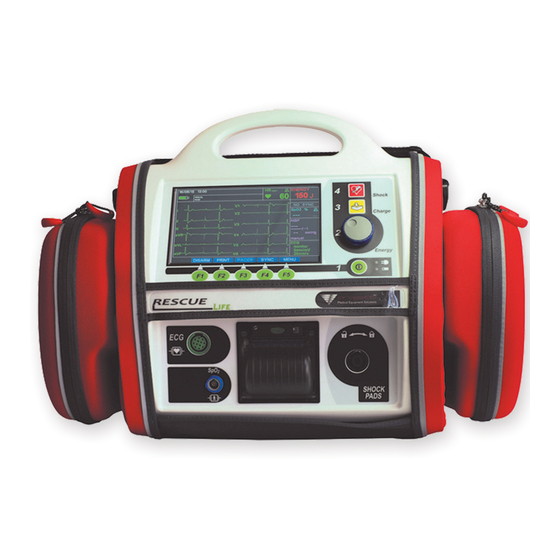
- Page 1 Distributed by USER MANUAL Rescue LIFE EXTERNAL BIPHASIC DEFIBRILLATOR and MONITOR ELPRO S.r.l. Rev. 3.1 Strada del Rondello, 5 10028 Trofarello (TO) ITALY...
- Page 2 Distributed by Rescue Life - User Manual Rev. 3.1...
-
Page 3: Table Of Contents
Distributed by Rescue Life - User Manual Rev. 3.1 TABLE OF CONTENTS GENERAL AND SAFETY INFORMATION ..............1 SAFETY INSTRUCTIONS ........................2 RESPONSIBILITY FOR INFORMATION ....................2 GENERAL ............................2 CAUTIONS ............................3 SHOCK OR FIRE HAZARDS ........................4 POSSIBLE ELECTRICAL INTERFERENCE ....................4 POSSIBLE IMPROPER DEVICE PERFORMANCE .................. - Page 4 Distributed by Rescue Life - User Manual Rev. 3.1 OPERATIONAL SCREEN FEATURES ...................... 23 SET-UP MENU ........................... 24 DEVICE AND PATIENT PREPARATION ..................26 Product Check........................... 26 How to test the defibrillator ......................26 HOW TO USE THE ECG PATIENT CABLE CONNECTION AND ELECTRODES PLACEMENT ......27 ECG CONNECTION ..........................
- Page 5 Distributed by Rescue Life - User Manual Rev. 3.1 TERMINOLOGY FOR NIBP ....................48 Warnings & Precautions DURING THE NIBP MESURAMENT ..............49 Cuff Selection & Placement ....................... 51 Activation and operation of the NIBP mode ..................52 Nibp set-up menu ..........................53 Operation sequence ..........................
- Page 6 Distributed by Rescue Life - User Manual Rev. 3.1 APPENDIX D ..........................76 TECHNICAL FEATURES ........................76 APPENDIX E – INSTRUCTION FOR USE FOR DISPOSABLE MULTIFUNCTION ELECTRODES FOR DEFIBRILLATOR ......................... 81 OPERATING INSTRUCTION ......................83 DECLARATION OF EC CONFORMITY ................... 88 APPENDIX E ..........................
-
Page 7: General And Safety Information
(BLS) and advanced life support (ALS) patient management protocols. RESCUE LIFE is designed to monitor the patient ECG signals and to deliver defibrillation shocks in MANUAL, ADVISORY or AED mode. This Operator’s Manual contains all the information that a user needs to operate the RESCUE LIFE properly. -
Page 8: Safety Instructions
GENERAL Assure yourself prior and after the use of the RESCUE LIFE that the unit is in safe and usable condition (cables integrity, pads, battery status). Assure that the battery charge, ECG trace, selected energy value, SYNC mode and status battery are well functioning. -
Page 9: Cautions
Distributed by Rescue Life - User Manual Rev. 3.1 CAUTIONS • MANUAL MODE DEFIBRILLATION MUST BE PERFORMED ONLY BY HIGHLY TRAINED MEDICAL PERSONNEL • EVER PUT IN CONTACT THE SHOCK PADDLES SHORT CIRCUIT • E SURE THAT BOTH SURFACES OF THE SHOCK PADDLES ARE COMPLETELY MOISTENED WITH GEL •... -
Page 10: Shock Or Fire Hazards
Distributed by Rescue Life - User Manual Rev. 3.1 SHOCK OR FIRE HAZARDS The defibrillator delivers up to 230 joules of electrical energy. Unless properly used as described in these operating instructions, this electrical energy may cause serious injury or death. -
Page 11: Possible Improper Device Performance
CELLULAR MOBILE TELEPHONES AND OTHERS AS THESE MIGHT INTERFERE WITH THE SIGNALS BEING ACQUIRED The RESCUE LIFE is classified as follows: Class II equipment, applied parts BF for pads, SpO2 and NIBP connector and CF for ECG cable (EN 60601-1). -
Page 12: Symbols Used
Distributed by Rescue Life - User Manual Rev. 3.1 SYMBOLS USED The symbols below may be found in this manual or in rear sticker or accessories of Rescue LIFE defibrillator. Symbol Description of symbol Identification of device Serial Number of device... - Page 13 Distributed by Rescue Life - User Manual Rev. 3.1 Follow local regulations on battery disposal or recycling CE Mark & Notified Body identification Fragile content, handle with care (on the package) To keep dry and to not exposure to weathering (on the...
-
Page 14: Introduction
Be sure that you have all the required supplies and accessories including cables and ECG paper, when you remove the RESCUE LIFE defibrillator/monitor from the container used for the shipment. Verify the defibrillator and all accessories for any sign of damage that may have occurred during shipping. -
Page 15: Cleaning And Maintenance
Distributed by Rescue Life - User Manual Rev. 3.1 CLEANING AND MAINTENANCE After each use, clean the defibrillator and the reusable pads using a soft, damp cloth moistened with any of the following solvents: • Water and soap. • Clorexina and water mixture (30 ml clorexina/liter of water). -
Page 16: Connecting To Power
Rescue Life - User Manual Rev. 3.1 CONNECTING TO POWER The RESCUE LIFE defibrillator/monitor operates on AC (line) power or with internal rechargeable Lithium-Ion battery. You can switch from battery to AC power or AC power to battery while the device is on and in use by plugging in or unplugging the AC power cord. -
Page 17: Battery Charge
When the message of the battery status displays a value under 25%, batteries should be charged. Insert the power supply cord in the RESCUE LIFE socket (located on the back side) and connect to the AC line. The battery status led will switch on. -
Page 18: Warranty
ELPRO S.r.l. has no information regarding the performance or effectiveness of its RESCUE LIFE defibrillators if they are used with defibrillation electrodes or other parts and supplies from other sources. Using defibrillation electrodes, adapter devices, or other parts and accessories from other sources than ELPRO S.r.l. -
Page 19: Service
If unauthorized personnel service the device during the warranty period, the warranty will become null and void. Regularly maintenance and testing of the RESCUE LIFE defibrillator/monitor and accessories will help to detect and prevent possible electrical and mechanical discrepancies. -
Page 20: Operational
The RESCUE LIFE can be supplied with (optional) 10 wire ECG cable. Optional module: RESCUE LIFE can be ordered with ADVISORY/AED mode, Pacemaker, as well as NIBP. On the AED version RESCUE LIFE includes a mass storage memory for recording the ECG trace and events. -
Page 21: Intended Use (Patients Group And Medical Conditions)
AED mode requires operator interaction in order to defibrillate the patient. AED MODE ON RESCUE LIFE IS RECOMMENDED FOR USE BY PERSONNEL WHO ARE AUTHORIZED BY A PHYSICIAN OR MEDICAL DIRECTOR AND HAVE... -
Page 22: Indications
Rescue Life - User Manual Rev. 3.1 INDICATIONS Asynchronous defibrillation – the shock delivery is not synchronized with the ECG 'R' peak. In asynchronous defibrillation, the RESCUE LIFE is indicated for use on patients with the following symptoms: • Unconsciousness •... -
Page 23: Front Panel Description
FRONT PANEL KEYS Keys on the right part are used to manage main defibrillation function. Power On-Off push button of RESCUE LIFE. At switch on, if the paddles are disconnected, the battery status and clock set-up screen will appear. In this case to start ECG monitoring press F1 key. -
Page 24: Function Keys (F1-F5)
When the red light inside this key is on it means that SHOCK RESCUE LIFE is ready to defibrillate. Pressing this key will BUTTON release the defibrillation shock. (This key is active only when disposable pads are used). -
Page 25: Light Indicators
Distributed by Rescue Life - User Manual Rev. 3.1 LIGHT INDICATORS Indicator (LED) CONNECTION TO AC LINE CASE A CASE A When the LED indicator is green lighted it informs that connection to AC line is carried. CASE B CASE B When the connection to AC line is removed the LED will switch off. - Page 26 For disconnecting the lead, pull the lead lever and turn left the connector. ECG PATIENT ECG patient cable input. RESCUE LIFE displays 3, 6 or 12 traces CABLE INPUT When the SpO sensor is connected, saturation values and heart rate are displayed.
-
Page 27: Start Screen Interface
Rescue Life - User Manual Rev. 3.1 START SCREEN INTERFACE The start screen will be displayed when RESCUE LIFE is switched on with the defibrillation paddles disconnected. Battery status and clock are shown. Using function keys it is possible to enter in different screens. -
Page 28: Operational Screen
Rev. 3.1 OPERATIONAL SCREEN At power ON, if the paddles are connected the RESCUE LIFE will start the operation. If the paddles are not connected the start screen will be displayed. Press START – F1 key to enter in operational screen. -
Page 29: Operational Screen Features
When the battery value is under 10% a message appears on display. Insert the power supply cord in RESCUE LIFE socket, otherwise system will shout down automatically in 2 minutes. During this time defibrillation functions are disabled. -
Page 30: Set-Up Menu
The entered values can be stored (when the ‘SAVE SETUP’) is selected and will be used as default values when RESCUE LIFE is switched on. If the user needs to change the values only for the actual session then after changing... - Page 31 Distributed by Rescue Life - User Manual Rev. 3.1 When menu screen is open the only keys to be active are F5 and Speed Dial. SET-UP MENU FIELDS: DEF MODE: select the function mode: manual (MANUAL), advisory (ADV) or semiautomatic (AED).
-
Page 32: Device And Patient Preparation
Distributed by Rescue Life - User Manual Rev. 3.1 The HR BEEP is not stored and when the machine is switched on, will be active (heart rate beep on). For patient safety reason, it can be set to off only for the actual working session. -
Page 33: How To Use The Ecg Patient Cable Connection And Electrodes Placement
Distributed by Rescue Life - User Manual Rev. 3.1 HOW TO USE THE ECG PATIENT CABLE CONNECTION AND ELECTRODES PLACEMENT The ECG (electrocardiogram) is a recording of the electrical activity of the heart. The ECG is obtained by placing either electrodes or paddles on the patient and allows the heart’s electrical activity to be monitored and recorded. - Page 34 Distributed by Rescue Life - User Manual Rev. 3.1 Precordial lead electrodes sites for the 10 wires ECG cable: Figure. I, II, III, aVR, aVL, aVF, V1, V2, V3, V4, V5, V6 derivations on frontal and orizzontal planes.
-
Page 35: Defibrillation Therapy
A direct current defibrillator applies a brief, intense pulse of electricity to the heart muscle. The RESCUE LIFE defibrillator/monitor delivers this energy through disposable pads, standard paddles or internal paddles applied to the patient’s chest. Successful resuscitation is associated to the length of time between the onset of a heart rhythm that does not circulate blood (ventricular fibrillation, pulseless ventricular tachycardia) and defibrillation. - Page 36 Distributed by Rescue Life - User Manual Rev. 3.1 Indications Defibrillation is a recognized means of terminating certain potentially fatal arrhythmias, like a ventricular fibrillation and symptomatic ventricular tachycardia. Delivery of this energy in the synchronized way is a method for treating atrial fibrillation, atrial flutter, paroxysmal supraventricular tachycardia, and, in relatively stable patients, ventricular tachycardia.
-
Page 37: How To Prepare The Patient
Distributed by Rescue Life - User Manual Rev. 3.1 HOW TO PREPARE THE PATIENT Evaluate the patient condition; he must exhibit the symptoms for which the defibrillation is indicated and these symptoms are: Unconsciousness Absence of normal breathing Lack of detectable pulse. -
Page 38: How To Prepare The Pediatric Patient
Distributed by Rescue Life - User Manual Rev. 3.1 HOW TO PREPARE THE PEDIATRIC PATIENT Apply the pads as shown in the picture. In the case of use of disposable plates. Open the package by tearing along the dotted line near the end of the pack. Remove the pads... -
Page 39: Defibrillation Mode
In MANUAL mode users have to analyze heart rhythm and decide time and energy value to use for the defibrillation while in other modes RESCUE LIFE automatically analyze heart rhythm. In ADVISORY mode (ADV) RESCUE LIFE only analyzes and suggest if patient needs defibrillation, after that users have to choose energy value, charge defibrillator and deliver the shock. -
Page 40: Defibrillator Procedure In Manual Mode
7. When the charge ends the red light on the SHOCK button will turn on indicating that RESCUE LIFE is ready for defibrillation. 8. To release the defibrillation shock, press both push buttons on the standard paddles. -
Page 41: Defibrillator Procedure In Advisory Mode (Adv)
150 J. To set advisory mode open menu and select advisory in DEF MODE. 2. Place the paddles on the patient chest and let RESCUE LIFE analyze the ECG trace in order to decide if defibrillation is necessary. -
Page 42: Automated External Defibrillation (Aed)
CPR when indicated. INDICATIONS FOR USE The RESCUE LIFE with the semiautomatic option is intended to be used by personnel who have been trained in its operation. The operator should be qualified by training in basic life support, CPR/AED. The device is indicated for emergency treatment of victims exhibiting the following symptoms of a sudden cardiac arrest: un-consciousness, absence of normal breathing and lack of detectable pulse. -
Page 43: Ecg Analysis Algorithm
“European Resuscitation Council (ERC) Guidelines for cardiopulmonary resuscitation (CPR)”, European Resuscitation Council, vol. 81/2010. Upon detecting a shockable cardiac rhythm, the RESCUE LIFE charges automatically at a 200J energy level and advises the operator to press the SHOCK button to deliver a shock;... -
Page 44: Selecting The Aed Operation Mode
LIFE guides operator by enunciating the time of 120 s. 8. At the end of CPR RESCUE LIFE analyzes heart rhythm again. If it recognizes a shockable rhythm it automatically will charge energy to a value of 200 Joule (point... - Page 45 Distributed by Rescue Life - User Manual Rev. 3.1 DO NOT TOUCH THE PATIENT DURING HEART RHYTHM ANALYSIS. DO NOT TOUCH THE PATIENT DURING DEFIBRILLATION. TURNING OFF THE DEFIBRILLATOR BEFORE RECORDING IS FINISHED IT WILL PRODUCE LOSS OF DATA IN THE MEMORY.
-
Page 46: Semiautomatic (Aed) Mode Flow Chart
Distributed by Rescue Life - User Manual Rev. 3.1 SEMIAUTOMATIC (AED) MODE FLOW CHART... -
Page 47: Audio And Text Prompts
Distributed by Rescue Life - User Manual Rev. 3.1 AUDIO AND TEXT PROMPTS PROMPTS MEANING Indicates that you have to connect the pads to the CONNECT PADS defibrillator. Indicates that the user have to attach the defibrillator ATTACH PADS electrode pads to the bare chest of the patient... -
Page 48: Pacemaker (Optional)
Non-invasive pacing is contraindicated for the treatment of ventricular fibrillation and asystole. On the operational screen, pressing the F3 key (PACER) the RESCUE LIFE will open the pacemaker mode and will display the pacemaker menu. IF THE PADDLES ARE NOT ATTACHED TO THE PATIENT THE MACHINE WILL NOT ENTER THE PACEMAKER MODE. -
Page 49: Pacemaker Screen
Distributed by Rescue Life - User Manual Rev. 3.1 PACEMAKER SCREEN In the PACING DATA area you can see pacing rhythm and current values and if pacing is activate or deactivate. Using function keys it is possible to set pacing parameter. -
Page 50: How To Prepare The Patient
Distributed by Rescue Life - User Manual Rev. 3.1 HOW TO PREPARE THE PATIENT The connection of the electrodes is possible in two ways, depending on what you want: • ANTERIOR-POSTERIOR Connection (only pacing). Front pad positioned on the left part of the chest, halfway between the xiphoid apophysis and the left nipple at the sites V2-V3. -
Page 51: Spo 2 Monitoring
Distributed by Rescue Life - User Manual Rev. 3.1 MONITORING The SPO Module measures functional oxygen saturation in the blood. The measurement determines the oxygenated hemoglobin as a percentage of the hemoglobin that can transport oxygen. Pulse oximetry works by having light emitting... -
Page 52: Pulse Oximetry Sensors
Other sensors from the manufacturer could also be used with the RESCUE LIFE. The following table shows all available sensors that may be used with the RESCUE LIFE. Choose the sensors to suit the weight of the patient. -
Page 53: Nibp (Non-Invasive Blood Pressure)
Rev. 3.1 NIBP (NON-INVASIVE BLOOD PRESSURE) INTRODUCTION The RESCUE LIFE NIBP option is based on the Advantage A+ module platform available in the series of oscillometric OEM NIBP technologies from SunTech Medical ® The Advantage series of OEM NIBP technologies provides the simplicity of the oscillometric technique of acquiring blood pressure with the most reliable, flexible and clinically accurate modules in the industry. -
Page 54: Terminology For Nibp
Distributed by Rescue Life - User Manual Rev. 3.1 TERMINOLOGY FOR NIBP Oscillometry The oscillometric method of blood pressure measurement is a non-invasive method that monitors the amplitude of cuff pressure changes during cuff deflation to determine arterial blood pressure. The cuff pressure is first elevated above the patient systolic blood pressure level and the cuff begins to deflate at a certain rate. -
Page 55: Warnings & Precautions During The Nibp Mesurament
Interpretation of blood pressure measurements should be made only by a physician or trained medical staff. The RESCUE LIFE NIBP module is designed to work with SunTech ® cuffs and hoses. The use of cuffs and hoses not supplied by SunTech ®... - Page 56 Distributed by Rescue Life - User Manual Rev. 3.1 correctly if used or stored outside the relevant temperature or humidity ranges described in the Performance specifications. Adverse Reactions Allergic exanthema (symptomatic eruption) in the area of the cuff may result, including the formation of urticaria (allergic reaction including raised edematous patches of skin or mucous membranes and intense itching) caused by the fabric material of the cuff.
-
Page 57: Cuff Selection & Placement
Distributed by Rescue Life - User Manual Rev. 3.1 CUFF SELECTION & PLACEMENT It is important to select the cuff size that is appropriate to the diameter of the patient’s upper arm. Use the Range Lines on the inside of the cuff to determine the correct size cuff to use. -
Page 58: Activation And Operation Of The Nibp Mode
ACTIVATION AND OPERATION OF THE NIBP MODE To activate the NIBP mode, press the ‘MENU’ (F5) key form the operational Rescue Life screen. On the menu select NIBP than ON using the jog. -
Page 59: Nibp Set-Up Menu
Distributed by Rescue Life - User Manual Rev. 3.1 On the bottom side of the screen the function keys (F1…F5) are the commands for the NIBP: START/STOP – F1: to start or abort the NIBP measurement in manual or automatic mode. -
Page 60: Operation Sequence
Distributed by Rescue Life - User Manual Rev. 3.1 By default when entering the NIBP mode the set-up is: PATIENT: ADULT MODE: MANUAL AUTO INTERVAL: 5 min PRINT MODE: AUTO OPERATION SEQUENCE Before any measurement please select the right patient type (set-up menu). - Page 61 Distributed by Rescue Life - User Manual Rev. 3.1 Appendix 1 Error Code List & Definitions If more than one error occurs during a single measurement, the higher numbered error code will be displayed. EC 1 Weak or no oscillometric signal Corrective Action: Check that the cuff is in the correct position.
- Page 62 Distributed by Rescue Life - User Manual Rev. 3.1 EC 87 Inflate Timeout, Air Leak or Loose Cuff Corrective Action: Check that the hose is connected to the system and the cuff. Check that the cuff is properly tightened. Check that the cuff is in the correct position.
- Page 63 Distributed by Rescue Life - User Manual Rev. 3.1 Appendix 2 Accessories Part # Description RLFS-0010.1 NIBP Cuff, Adult RLFS-0010.2 NIBP Cuff, Pediatric RLFS-011 NIBP Cable Appendix 3 Specifications • Method of Measurement: Oscillometric. Diastolic values correspond to Phase 5 Korotkoff sounds.
- Page 64 Distributed by Rescue Life - User Manual Rev. 3.1 Pulse Rate Accuracy: • ± 2% or ± 3 BPM, whichever is greater • Cuff Deflate Rate: Deflation step size varies with heart rate, cuff pressure and cuff volume. • Initial Inflation Pressure:...
-
Page 65: Data Base
Distributed by Rescue Life - User Manual Rev. 3.1 • Patient Safety: Internal operating software ensures that: Maximum cuff inflation time is limited to 75 seconds Duration of blood pressure reading is limited to: 130 seconds (Adult mode) 120 seconds (Adult Motion Tolerant mode) -
Page 66: Recording
Each time the machine is switched on, automatically a File with the current date will be created. In each File RESCUE LIFE can store up to 30 Records of 1 minute length. Each Record holds the actual ECG trace data (acquired from lead II of pads or the ECG patient cable) and the initial recording time stamp. -
Page 67: Data Retrieval
Distributed by Rescue Life - User Manual Rev. 3.1 To scroll next 10 record. DOWN – F1 To scroll previous 10 record. TOP – F2 PRINT - F3 To print data. BACK - F4 To move to previous selection. EXIT – F5 To exit Data Base. -
Page 68: Date And Time Setup
1 second (shock event). DATE AND TIME SETUP To set-up the real time clock, switch on the RESCUE LIFE with paddles connector disconnected. On the screen will be displayed the battery status, the date and time. The SETCLK-F4 key enables the clock set-up. -
Page 69: Auto Test
It is advisable to do the test at least once a week. It 'also possible to print the report. On the initial screen, press the function key TEST - F3 to access the test screen. Press START – F1 key to start auto test. RESCUE LIFE will do internal tests and will show results. - Page 70 Distributed by Rescue Life - User Manual Rev. 3.1 If during the check the RESCUE LIFE founds some fault, the system will indicate it. Note error code communicate authorized technical service. Pressing the PRINT - F3 you can print the test report.
-
Page 71: Rescue Life Checklist
Distributed by Rescue Life - User Manual Rev. 3.1 RESCUE LIFE CHECKLIST ELPRO Srl recommend using the following checklist to monitor the status of RESCUE LIFE. It includes all the tests for checking the functionality and the safety. Operator should test the defibrillator at least once a week. -
Page 72: Clinical Information
Distributed by Rescue Life - User Manual Rev. 3.1 APPENDIX A CLINICAL INFORMATION Sudden cardiac arrest (SCA) associated with ventricular fibrillation (VF) remains a leading cause of unexpected death in the Western world. It has been estimated that chances for survival from SCA decrease approximately 7% to 10% with each passing minute and that survival rates after 12 minutes are only 2% to 5%. - Page 73 Distributed by Rescue Life - User Manual Rev. 3.1 Research has shown that chest resistance can vary significantly from patient to patient. Patients with low impedance are generally easier to defibrillate because the flow of current meets little resistance. Those with higher impedance may be more difficult to defibrillate.
-
Page 74: Ease In Compensation Of Patient Impedance
Distributed by Rescue Life - User Manual Rev. 3.1 EASE IN COMPENSATION OF PATIENT IMPEDANCE Through Biphasic technology, defibrillation shock delivery is controlled while taking into consideration the patient’s impedance. The patient’s impedance is measured through the defibrillator electrodes. According to the measured patient’s impedance, e-cube Biphasic technology adjusts the duration of current flow to optimize the effectiveness of the shock delivery. - Page 75 Distributed by Rescue Life - User Manual Rev. 3.1...
-
Page 76: Enough Energy For Restoring Heart Rhythm
Distributed by Rescue Life - User Manual Rev. 3.1 Extensive animal and human data with implanted devices demonstrate that biphasic waveforms offer substantial reductions in defibrillation thresholds and produce less myocardial dysfunction than monophasic waveforms [1], [2], [3], [4]. The defibrillation efficacy of the 150-J biphasic waveform was superior to that of the 200-J to 360-J conventional escalating-energy monophasic waveforms for 115 patients who presented with VF [5]. - Page 77 Distributed by Rescue Life - User Manual Rev. 3.1 In a multicenter, randomized, controlled trial of 150J biphasic waveform compared with 200J and 360J monophasic waveforms done in humans, Schneider et al [5] showed that “the 150-J biphasic waveform defibrillated at higher rates, resulting in more patients who achieved a return of spontaneous circulation.
-
Page 78: References
Distributed by Rescue Life - User Manual Rev. 3.1 REFERENCES [1] Chapman PD, Vetter JW, Souza JJ, Wetherbee JN, Troup PJ. Comparison of monophasic with single and dual capacitor biphasic waveforms for nonthoracotomy canine internal defibrillation. J Am Coll Cardiol. 1989;14:242.5. -
Page 79: Accessories And Modules
Distributed by Rescue Life - User Manual Rev. 3.1 APPENDIX B ACCESSORIES AND MODULES Part # Description RLFS-001 Standard Electrodes for defibrillation RLFS-002.1 5-leads ECG cable RLFS-002.2 10-leads ECG cable RLFS-004.1 Adult SpO2 sensor RLFS-004.2 Pediatric SpO2 sensor RLFS-005 AC Adapter... -
Page 80: Technical Specifications
Distributed by Rescue Life - User Manual Rev. 3.1 APPENDIX C TECHNICAL SPECIFICATIONS Waveform time-impedance Following flow-charts show typical defibrillation impulses considering the impedance between the defibrillation electrodes for a maximum of 230 Joule: 150J, 25ohm 230J,50ohm 230J,75ohm 230J,100ohm 230J,125ohm... -
Page 81: Impendance Limits
Rescue Life - User Manual Rev. 3.1 IMPENDANCE LIMITS RESCUE LIFE does not release the shock if the patient impedance is less than 25 ohm or over 200 ohm. SYNC/NO SYNC MODE When the RESCUE LIFE is on it is automatically set on no-sync mode. -
Page 82: Technical Features
Distributed by Rescue Life - User Manual Rev. 3.1 APPENDIX D TECHNICAL FEATURES ECG Monitoring • Patient connection: Defibrillation pads and 5 or 10 wire ECG cable. • Bandwidth: 0.6 to 40 Hz (-3 dB) in monitor mode. 0.05 to 120 Hz (-3 dB) in diagnostic mode. - Page 83 Distributed by Rescue Life - User Manual Rev. 3.1 Display • LCD Display color TFT. • LCD Dimensions: high contrast 7 inches 800X600 pixels. Device Dimensions • Dimensions: 369 x 240 x 340 mm (L x W x H). • Weight 5.5 kg approximately.
- Page 84 Distributed by Rescue Life - User Manual Rev. 3.1 AED mode • Energy: Fixed energy at 200 J. • Protocol: ERC 2010 CPR Guidelines with voice and text prompts. • Shockable rhythms: VF with amplitude >0.15 mV and VT with rhythm >150 bpm.
- Page 85 Distributed by Rescue Life - User Manual Rev. 3.1 NIBP (optional) • Technique: oscillometric. • NIBP Accuracy: Meets ANSI/AAMI SP10-2002, EN 1060-4. • Patient Application: Adult/Paediatric/Neonatal. • Systolic Range: Adult: 40-260mmHG, Pediatric: 40-160 mmHG, Neonatal: 40-130 mmHG. • Range MAP: Adult: 26-220 mmHG, Paediatric: 26-133mmHG, Neonatal: 26-110 mmHG.
- Page 86 Distributed by Rescue Life - User Manual Rev. 3.1 Printer • Type: Integrated thermal printer 200 dpi for ECG traces and events documentation hardcopy including HR/SpO values. • Paper Speed: 5, 10, 25, 50 mm/sec. • Paper width: 58 mm.
-
Page 87: Appendix E - Instruction For Use For Disposable Multifunction Electrodes For Defibrillator
Distributed by Rescue Life - User Manual Rev. 3.1 APPENDIX E – INSTRUCTION FOR USE FOR DISPOSABLE MULTIFUNCTION ELECTRODES FOR DEFIBRILLATOR Disposable Multifunctional Electrodes for Defibrillator (defibrillation, synchronized stimulation, transcutaneous cardiac stimulation, ECG monitoring) DFBAD01STD / DFBAD01PRC (Adult) DFBPED01STD / DFBPED01PRC (Pediatric) V2.0... - Page 88 Distributed by Rescue Life - User Manual Rev. 3.1 References Ian Jacobs, Kjetil Sunde, et al. “Part 6: Defibrillation. 2010 International Consensus on Cardiopulmonary Resuscitation and Emergency Cardiovascular Care Science With Treatment Recommendations” Circulation 2010;122:S325-S337 Jerry Nolan et al. “European Resuscitation Council Guidelines for Resuscitation 2010” Resuscitation Vol.
-
Page 89: Operating Instruction
Distributed by Rescue Life - User Manual Rev. 3.1 DISPOSABLE MULTIFUNCTION ELECTRODES OPERATING INSTRUCTION CAUTION Federal (USA) law restricts this device to sale by or on the order of a physician. IMPORTANT The product is intended for use in non-sterile environment by authorized personnel only. Before using the product, the user should deeply understand these instructions. - Page 90 Distributed by Rescue Life - User Manual Rev. 3.1 In paediatric applications the Guidelines for cardiopulmonary resuscitation recommend a supply of energy of 2-4J / kg; the recommended starting level is of 2 J / kg and it is preferable not to exceed 100J in order to avoid burns [5].
- Page 91 Distributed by Rescue Life - User Manual Rev. 3.1 POSITIONING AND POLARITY The international guidelines indicate various placements as equally effective for the treatment of atrial or ventricular arrhythmias [5]. The following figures show the application sites commonly used and recommended by most manufacturers of defibrillators.
- Page 92 Distributed by Rescue Life - User Manual Rev. 3.1 ATTENTION Paediatric multifunction electrodes marked with the symbol shown beside are indicated for use with automatic defibrillators. • The electrode choice should be based on the evaluation of chest size and weight of the patient. Paediatric electrodes used beyond the specified energy limit may cause also major skin burns;...
- Page 93 Distributed by Rescue Life - User Manual Rev. 3.1 DISPOSAL Refuses deriving from health structures must be disposed in according to the regulation in force. WARRANTY AND LIMITATIONS PROGETTI S.r.l. guarantees that the product complies with Directive 93/42/EEC. No responsibility may be ascribed to the producer who shall not be held liable for medical costs, director indirect damage due to lacking function or malfunction of the above product, when used differently from the instruction for use.
-
Page 94: Declaration Of Ec Conformity
MANUFACTURER: ELPRO S.r.l. Strada del Rondello, 5 10028 Trofarello (TO) ITALY PRODUCT: Defibrillator MODEL: Rescue LIFE GMDN Code: 17882 CLASS: II b STANDARDs REFERENCES: EN ISO 13485:2016 EN 60601-1:2006+A1:2013+A12:2014, EN 60601-1-2:2015, EN 60601-2-4:2011, EN 60601-2-27:2014, EN 60601-2-31:2008+A1:2011, EN 62353:2014, EN 62366-1:2015, EN 60601-1-6:2010, EN 62304:2006, EN ISO 14971:2012, EN ISO 15223-1:2012, MEDDEV 2.7/1 Rev.4, MEDDEV 2.12-1 Rev.8, MEDDEV 2.12/2 Rev.2... -
Page 95: Warranty Certificate
Distributed by Rescue Life - User Manual Rev. 3.1 APPENDIX E WARRANTY CERTIFICATE WARRANTY CONDITIONS This device is warranted against defects in materials and workmanship. The warranty does not apply if the product has not been properly used as suggested in the user manual, has been damaged by accident or misuse, has been damaged as the result of service or modification by an entity other than ELPRO S.r.l.. - Page 98 Rescue Life - User Manual vers. 3.1 Distributed by ELPRO S.r.l. Strada del Rondello, 5 10028 Trofarello (TO) ITALY www.elpromedical.com...
Need help?
Do you have a question about the Rescue LIFE and is the answer not in the manual?
Questions and answers