Table of Contents
Advertisement
Quick Links
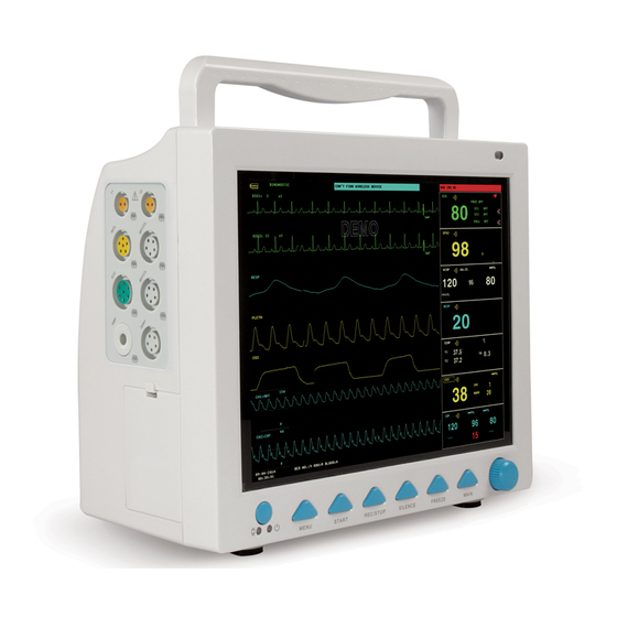
PROFESSIONAL MEDICAL PRODUCTS
NEW CMS 8000 MULTIPARAMETER
PATIENT MONITOR
User Manual
35152 / CMS8000
CONTEC MEDICAL SYSTEMS CO., LTD
No.112 Qinhuang West Street,
Economic & Technical Development Zone,
Qinhuangdao, Hebei Province, PEOPLE'S REPUBLIC OF CHINA
Made in China
Shanghai International Holding Corp. GmbH (Europe)
Eiffestrasse 80, 20537 Hamburg, Germany
0123
Advertisement
Table of Contents
Troubleshooting

Subscribe to Our Youtube Channel
Related Manuals for Gima CMS 8000


Summary of Contents for Gima CMS 8000
- Page 1 PROFESSIONAL MEDICAL PRODUCTS NEW CMS 8000 MULTIPARAMETER PATIENT MONITOR User Manual 35152 / CMS8000 0123 CONTEC MEDICAL SYSTEMS CO., LTD No.112 Qinhuang West Street, Economic & Technical Development Zone, Qinhuangdao, Hebei Province, PEOPLE’S REPUBLIC OF CHINA Made in China Shanghai International Holding Corp. GmbH (Europe)
- Page 2 Copyright Statement Our company owns all rights to this unpublished work and intends to maintain this work as confidential. We may also seek to maintain this work as an unpublished copyright. This publication is to be used solely for the purposes of reference, operation, maintenance, or repair of our equipment.
- Page 3 Warranty Workmanship & Materials Our company guarantees new equipment other than accessories to be free from defects in workmanship and materials for a period of 18 months (six months for multi-site probes and SpO sensor) from date of shipment under normal use and service.
- Page 4 Return Policy Return Procedure In the event that it becomes necessary to return a unit to our company, the following procedure should be followed: Obtain return authorization. Contact our Service Department and tell us the product serial number. The number is marked on the outside of the shipping package.
-
Page 5: Table Of Contents
Contents Chapter 1 Safety ..............................1 1.1 Safety information .............................1 1.2 Precautionary measures ..........................2 Chapter 2 General ..............................3 2.1 Introduction ...............................3 2.2 Contraindications ............................3 2.3 Main unit ..............................3 2.4 Display...............................9 Chapter 3 Installation ............................11 3.1 Open the Package and Check ........................11 3.2 Environmental requirement ........................12 3.3 Install the Monitor ...........................12 3.4 Connect the Power Cables ........................12... - Page 6 Chapter 7 Recording ..............................34 7.1 General Information for Recorder ......................34 7.2 Recording Type............................34 7.3 Recording Start&Stop..........................36 7.4 Recorder Operations and Status Messages ....................37 Chapter 8 Recall ..............................39 8.1 Trend Graph .............................39 8.2 Trend Table ..............................41 8.3 NIBP recall ..............................42 8.4 Alarm recall .............................42 8.5 SD recall ..............................43 Chapter 9 Drug Calculation and Titration Table ....................48 9.1 Drug Calculation .............................48...
- Page 7 13.1 Introduction ............................74 13.2 Safety information ..........................74 13.3 Measurement Limitations ........................75 13.4 Measurement steps ..........................75 13.5 Operation hints ............................76 13.6 Amend results ............................77 13.7 NIBP display............................77 13.8 NIBP SETUP ............................77 13.9 NIBP Calibration ...........................80 13.10 NIBP Alarm Message ..........................80 Chapter 14 TEMP Monitoring ..........................83 14.1 Introduction ............................83 14.2 Safety information ..........................83 14.3 Measurement ............................83...
- Page 8 17.4 Check for battery performatnce ......................100 17.5 Battery maintenance ..........................101 17.6 Battery recycle .............................101 Chapter 18 Maintenance and Cleaning ........................103 18.1 Introduction ............................103 18.2 Cleaning ...............................103 18.3 Disinfection ............................105 Chapter 19 Maintenance ............................106 19.1 Check ..............................106 19.2 Troubleshooting ...........................106 19.3 Maintenance plan ..........................108 Chapter 20 Accessories ............................109 20.1 ECG Accessories ..........................109 20.2 SpO...
-
Page 9: Chapter 1 Safety
Chapter 1 Safety 1.1 Safety information WARNING Before using the device, the equipment, patient cable and electrodes etc. should be checked. Replacement should be taken if there is any evident defect or signs of aging which may impair the safety or performance. The Monitor is intended for clinical monitoring application with operation only granted to appropriate medical staff. -
Page 10: Precautionary Measures
If you have questions concerning disposal of the product, please contact our company or representative institution. When you have questions about the integrity of the external grounding of the monitor and its arrangement, the internal battery must be used for operation. Electromagnetic fields can affect the performance of the monitor, so other equipment used near the monitor must meet the appropriate EMC requirements. -
Page 11: Chapter 2 General
Chapter 2 General 2.1 Introduction Structure and composing: main unit, accessories (ECG lead cables, SpO sensor, NIBP extension tube, NIBP cuff, TEMP probe, etc.) and power cord. The monitor is applicable for the clinical monitoring of adult, pediatric and neonate(SpO function is inapplicable on neonate in American). - Page 12 CMS8000 CMS9000...
- Page 13 AC indicator: On: the monitor is connected to AC power supply; Off: the monitor is disconnected from AC power supply. Battery status indicator: it displays green and flickers under battery-powered condition, it always displays orange in charging state and green after fully charged. Or Running indicator: when the device turns on, this indicator will be lighting, when it tuns off, this indicator will go out.Please make the object as the standard.
- Page 14 Side view CMS7000 CMS8000 CMS9000...
- Page 15 T1: Socket for channel 1 TEMP probe : Socket for SpO sensor ECG: Socket for ECG cable NIBP: Socket for NIBP cuff T2: Socket for channel 2 TEMP probe Note: [6] and [7] can not be connected to a function IBP/CO : IBP or CO interface...
- Page 16 CMS9000 Network interface: standard RJ45 interface, connecting with the central monitoring system of our company by network cable USB port: connecting with external memory devices Equipotential grounding terminal: when the monitor is used together with other equipment, use a cable to connect other equipment to the equipotential terminal of the monitor, which eliminates the ground potential difference between the different devices to ensure safety.
-
Page 17: Display
2.4 Display The monitor adopts high resolution color TFT LCD screen, which clearly displays all physiological parameters and waveforms of the patient. The following figure is a standard interface in normal monitoring state. 1.Battery indicator The battery works normally, the solid part represents battery level. Battery is low, it needs to be charged immediately, and the monitor generates low battery alarm. - Page 18 7.Waveform area Mainly displaying the waveform of physiological parameters, the name of each waveform is on the top left. ECG lead is selectable according to the demand. The filter mode is displayed at the top of screen. Gain of each channel is displayed above its waveform, at the right side of the waveform, there is a scale of one millivolt.
-
Page 19: Chapter 3 Installation
Chapter 3 Installation The portable monitor is designed to comply with relevant safety requirements of IEC 60601-1, IEC 60601-2-27 and IEC 80601-2-30 for medical electrical equipment. The system has a floating input for defibrillation proof and electrosurgical knife protection. If the correct electrodes (see the section about ECG Monitoring) are used and placed according to the manufacturer's instructions, the display will be restored within 5 seconds after defibrillation. -
Page 20: Environmental Requirement
package is intact before use, especially the disposable accessories. If any damage is found, please don't put is into use. NOTE: Keep the package and packing materials for possible future transportation or storage. 3.2 Environmental requirement Please obey the following instructions to ensure the safety of electrical installation. The environment for potable monitor using shall properly away from vibration, dust, corrosive or flammable gas, extreme temperature or humidity and so on. -
Page 21: Power On
portable monitor is equipped with a removable three-wire cable, when it is inserted into a matching three-wire socket, the device will be grounded through the ground wire in the power cord. If there is no three-wire socket, consult the hospital's electrical management staff. WARNING Do not insert the three-core wire into a two-core socket. -
Page 22: Power Off
• The red and yellow alarm lamp respectively light. • The system beeps for each time of powering on, and the LED indicator on control panel or the screen flickers once. If no beep sound or flickering, please stop using this monitor, and contact out company for maintenance. -
Page 23: Chapter 4 System Menu
Chapter 4 System Menu This monitor features flexible configurations. You can customize monitoring content, waveform sweep speed, sound volume, and output content.Press the MENU button on the front panel of the monitor, the interface shown in the following figure will appear: 4.1 Patient Information Setup Select the "PATIENT SETUP"... -
Page 24: Default Setup
After clicking the "DELETE" button in this menu, a dialog box "CONFIRM TO DELETE" will pop up, you could select "YES" or "NO" to decide whether to clear current patient information. NOTE: If you choose "YES", the information of current patient will be deleted. Please click "SAVE"... -
Page 25: System Setup
4.4 System setup Select the "SYSTEM SETUP" item in the "SYSTEM MENU", the following menu will appear: In the "SYSTEM SETUP" menu, user can set the following items. 4.4.1 Face select The system provides 5 display modes: "STAND SCREEN", "OxyCRG SCREEN", "TREND SCREEN", "BIG CHAR" and "VIEWBED SCREEN". - Page 26 1. STAND SCREEN The "STAND SCREEN" is the default setting. If the current screen is not the standard screen, you may enter the standard screen by selecting "STANDARD SCREEN" and then selecting "EXIT" in FACE SELECT menu. Stand Screen 2. OxyCRG SCREEN If you want to enter the following interface, select "OxyCRG SCREEN"...
- Page 27 ①. Trend length This label allows you to select the time duration of the trend graphs displayed. You can select either 1 min, 2 min or 4 min. ②. Compressed RESP waveform/RR trend With this label, you can select to display the compressed respiration waveform or the RR trend. You can select either RESP WAVE or RR.
- Page 28 4. BIG CHAR To view the parameter more clearly in a long distance. Big Char 5. VIEWBED SCREEN This monitor can display one parameter waveform and all measured data from another patient monitor in the same monitoring network system. To enter the following screen, open "FACE SELECT" menu, select "VIEWBED SCREEN" item, and then select "EXIT".
- Page 29 patient's name of the viewbed monitor. ② Viewbed parameter area All parameter data of the viewbed monitor is displayed in this area. ③ Viewbed waveform label The viewbed waveform label allows you to select a waveform of the viewbed monitor. ④...
- Page 30 NOTE: The system time shall be set when turning on the monitor (if you need to set the system time); otherwise, when you review the content containing time information, the system may not display the correct time. 4.4.7 Alarm setup Please refer to the sections about "Alarm".
-
Page 31: Machine Version
3. Once making a wrong selection, you can push the knob on the event again to give up the selection. Select "EXIT" to exit the menu and consequently the selection will come into effect. 4.4.10 SD operate Please refer to the chapter related to SD Recall. 4.5 Machine version Select the "VERSION"... - Page 32 4.7.2 Factory maintain 1. You need to select the "MAINTAIN" item in the "SYSTEM MENU", then select "FACTORY KEY". 2. Input the password to enter the factory maintain menu, this function is available for specific maintenance personnel of our company only. 4.7.3 Network configuration Click "NIT CONFIG"...
- Page 33 The Server IP is fixed "202.114.4.119". Once the monitor specifies the port number, the program will automatically obtain the local IP address and the port to be connected. CUSTOM In this mode, the IP address and subnet mask of the server, as well as the two items of this monitor can be set by user.
-
Page 34: Demo
(dynamic IP of this monitor, gateway, DNS, etc.) through the DHCP. If specified IP is used, please set the IP address of this monitor and subnet mask, click "LOCAL IP CONFIG" button, the following menu will pop up: Wire When the network type is CMS, just make sure the connection between the device and the central station is successful. (The IP address of the server is 202.114.4.119, the IP address of this monitor and subnet mask are generated by the port number.) When the network type is CUSTOM, make sure the monitor is connected to the router. -
Page 35: Chapter 5 Alarm
Chapter 5 Alarm When the patient being monitored appears abnormal changes in vital signs, or the monitor itself occurs failure and fails to monitor the patient, it will remind the medical workers through sound, light, etc. WARNING In any single area (e.g. intensive care unit or cardiac operating room), there is a potential hazard that the same or similar devices use different alarm preset. -
Page 36: Alarm Mode
by the system, which can not be changed by user. The level of most of the physiological alarms need to be set by user, such as alarm limits. 5.3 Alarm mode When alarm occurs, the monitor may draw the user’s attention in three ways as below: Audio alarm Light alarm Alarm message... - Page 37 user could set information about alarm sound and so on. ALARM VOL: selective from 1~7, 1 is the minimum volume, 7 is the maximum volume. ALM REC TIME: three options: 8 s, 16 s, 32 s. ALM PAUSE TIME: two options: 1 min and 2 min. ALM TYPE: UNLATCH..
-
Page 38: Alarm Status
normal alarm status. Parameter alarm setup 1. The parameter alarms can be set in "PARAM ALM SETUP", or their individual parameter menu. 2. When a parameter alarm is off, a symbol " " displays near the parameter. 3. For the parameter whose alarm is set to "ON", the alarm will be triggered when at least one of the parameters exceeds alarm limit. -
Page 39: Measures For Alarm Occurs
5.5.1 Silence Keep pressing the "SILENCE" button (over 1 second) on the control panel will turn off all the sounds. In SILENCE status, pressing the "SILENCE" button (no more than 1 second) will switch to the "ALARM PAUSE" status, and the alarm will be suspended temporarily in accordance with the time set before. -
Page 40: Chapter 6 Freeze
Chapter 6 Freeze When monitoring a patient, you may freeze the waveform to view it carefully. Up to 34 seconds waveform can be reviewed. Besides, the frozen waveform can be output by recorder. The Freeze function of this monitor has following features: Freeze status can be activated under any operating screen. -
Page 41: Recording Frozen Waveform
upward under the right side of the last waveform. There is also a time scale beside the arrow. "0 s" is used to mark the moment when waveforms are frozen. With waveforms moving right, this time mark will turn into "-1 s, -2 s, -3 s…". 6.4 Recording Frozen Waveform In the Freeze status, you may output displayed frozen waveforms via the recorder. -
Page 42: Chapter 7 Recording
Chapter 7 Recording NOTE: The recorder is an optional component. 7.1 General Information for Recorder A thermal array recorder is used for the Monitor. Performance of the Recorder Recording speed: 25 mm/s or 50 mm/s. Waveform recording width: 48mm It can record up to 2 waveforms. The time and waveform of real-time recording are user-configurable. - Page 43 NOTE: If certain recording is in process, and another parameter demands alarm recording, it will only be executed after the earlier recording is finished. Auto Recording The monitor starts a recording for 8 seconds according to interval time set in the "TIMING REC TIME" of the "RECORD SETUP "...
-
Page 44: Recording Start&Stop
Titration Table The monitor can print out the messages in the current TITRATION interface. Notes on Recording Recording type: Real-time recording Periodic recording Para alarm recording Arrhythmia recording Freeze waveform recording Trend Graph Trend Table Para alarm review NIBP review Titration Table Alarm parameters, alarm time and freeze time Patient bed number, sex, height, weight, date of birth, admission date... -
Page 45: Recorder Operations And Status Messages
currently displayed trend graph. Pick "REC" button in the "TREND TABLE" menu to printout the currently Trend table recording displayed trend table. Select "REC" button in the "ARR RECALL" menu to print out the currently Arrhythmia review recording displayed arrhythmia waveform and related parameters. Access the "ALARM RECALL"... - Page 46 Press the switch to open the recorder door. Insert a new roll of paper into the paper cassette, put the paper correctly and pay attention to the edges. Give out the paper from the recorder outlet. Close the recorder door. NOTE: Be careful when inserting paper.
-
Page 47: Chapter 8 Recall
Chapter 8 Recall The monitor provides 480-hour trend data of all parameters, storage of 4800 groups of NIBP measurement results and 72 alarm events. All these data can be output through recorder. By using SD card, the trend data and 72-hour ECG waveform can be reviewed. - Page 48 To change the display scale Pick the "ZOOM" button to adjust the y-axis scale and thus change the trend curve in proportion. The value beyond maximum value will be represented by the maximum value. To obtain trend data of a specific time Select "CURSOR"...
-
Page 49: Trend Table
8.2 Trend Table The latest 480-trend table data can be displayed at every 1 min, 5 min, 10 min, 30 min, or 60 min. Pick TREND TABLE in the SYSTEM MENU to call up the following menu: Time corresponding to each group of trend data is displayed at the leftmost list with date in brackets. Marked events are listed under the "EVENT"... -
Page 50: Nibp Recall
Adjust the "RESOLUTION" to the option that you need. Select the "UP/DOWN" button, turn the knob to view the NIBP trend data at different time. If you need to print the NIBP trend table, pick REC button, the recorder will print the NIBP trend data. If you need to print all trend tables, select "REC ALL"... -
Page 51: Sd Recall
① Time span (Format: year/month/day/hour/minute--- year/month/day/hour/minute). ② Event type. ③ Serial number (Format: NO. xx of XX ). ④ The value at the moment of alarming. NIBP result is excluded. ⑤ Two channels waveforms, stored for 8 s/16 s/32 s. To view all waveforms during the alarming process Pick L-RIGHT and turn the knob to view all 8/16/32 seconds waveforms stored. - Page 52 NOTE: Data can be reviewed only after SD card has been mounted successfully for 90 seconds . Otherwise the two buttons "REVIEW TREND" and "REVIEW ECGWAVE" are invalid. 4. Review trend Review trend ① Select "REVIEW TREND" item in SD OPERATE menu. The following menu will pop up.
- Page 53 ③ Review trend data Select an item in above menu by using the cursor, then press "REVIEW" button, the trend data will be displayed in a list. The resolution is 1 minute. The buttons are: Page UP/ PAGE DOWN: to view trend data of different time. LIGHT/ RIGHT: to view trend data of different parameter.
- Page 54 Review ECG waveform ① Select the "REVIEW ECG WAVE" button in SD OPERATE menu, then choose a specific patient to review. ② Select time span you want to review ECG data is saved in many different files. It need save ECG data in a new file per half an hour. For example, "2014-09-03 14:15"...
- Page 55 ③ Review ECG waveform The time span of one window is 5s. The window can display 3 channels ECG waveform. When the lead type is "5 LEADS", it displays ECG I, ECG II and ECG V. 5-Lead When the lead type is "3 LEADS", it can displays only one channel waveform. The ECG lead is the same with the one displayed on the monitor.
-
Page 56: Chapter 9 Drug Calculation And Titration Table
Chapter 9 Drug Calculation and Titration Table This Portable Patient Monitor provides drug calculation and titration table display functions for fifteen drugs and outputs the content of titration table on the recorder. 9.1 Drug Calculation The drug calculations that can be performed by the system are AMINOPHYLLINE, DOBUTAMINE, DOPAMINE, EPINEPHRINE, HEPARIN, ISUPREL, LIDOCAINE, NIPRIDE, NITROGLYCERIN and PITOCIN. -
Page 57: Titration Table
Each drug has its fixed unit or unit series. Operator must select the proper unit following the doctor’s instruction. The unit will automatically adjust itself in its unit series according to the input value. If the result expressed by this unit exceeds the range, the system will display "---". After entering a value, a conspicuous prompt will appear in the menu warning the operator to confirm the correctness of the entered value. - Page 58 Method to operate the titration table: In the TITRATION table, turn the knob to pick BASIC item. Press and turn the knob to select either INF RATE or DOSE or DRIP RATE. Move the cursor to STEP item. Press the knob to select step. The selectable range is 1 ~ 10. Move the cursor to DOSE TYPE item.
-
Page 59: Chapter 10 Ecg Monitoring
Chapter 10 ECG Monitoring 10.1 Introduction The ECG monitoring produces a continuous waveform of the patient's cardiac electric activity to enable an accurate assessment of patient's current physiological state. Only proper connection of the ECG cables can ensure satisfactory measurement. The monitor displays 2-channel ECG waveforms at the same time in normal working, and provides 3/5-lead monitoring, ST segment analysis and arrhythmia analysis. -
Page 60: Monitoring Procedure
communication error" or "ECG module initialization error" appears, the monitor will stop monitoring automatically, and the prompt system alarm, which is a high-level alarm. For protecting environment, used electrodes must be recycled or disposed properly. 10.3 Monitoring Procedure 10.3.1 Preparation Prepare the patient's skin prior to placing the electrodes. - Page 61 Brown/Yellow White/Yellow Brown/Green White/Green Brown/Blue White/Brown Brown/Orange White/Black Brown/Purple White/Purple The 3-lead The placement of 3-lead electrodes is shown as below: RA (right arm): under the clavicle, near the right shoulder LA (left arm): under the clavicle, near the left shoulder LL (left leg): left lower quadrant The 5-lead The placement of 5-lead electrodes is shown as below:...
- Page 62 For 5-lead set, attach the chest electrode (V) to one of the indicated positions as below: V1: On the 4 intercostal space at the right sterna margin. V2: On the 4 intercostal space at the left sterna margin. V3: Midway between V2 and V4 electrodes. V4: On the 5 intercostal space at the left clavicular line.
- Page 63 Recommended ECG Lead Placement for Surgical Patients The placing of the ECG leads will depend on the type of surgery that is being performed. For example, with open chest surgery the electrodes may be placed laterally on the chest or on the back. In the operating room, artifacts can sometimes affect the ECG waveform due to the use of ES (Electrosurgery) equipment.
-
Page 64: Ecg Screen Hot Keys
10.4 ECG Screen Hot Keys The following figure is an interface of 5-lead monitoring, only for reference. ③ ① ② ④ ⑤ ECG Hot Key Errore. L'origine riferimento non è stata trovata. Leads of channel 1: The selectable leads are I, II, III, aVR, aVL, aVF, V. When the ECG is 5-lead, the selectable leads are: I, II, III, aVR, aVL, aVF;... -
Page 65: Ecg Setup
Only in Diagnostic mode, the system can provide non-processed real signals. In Monitor or Surgery mode, ECG waveforms may have distortion of different extent. In either of the latter two modes, the system can only show the basic ECG, the results of ST analysis may also be greatly affected. In Surgery mode, results of ARR analysis may be somewhat affected. - Page 66 "OFF" to disable the alarm function, and there will be a in parameter area. ALM LEV: selectable from "HI" and "MED". Level HIGH represents the most serious alarm. ALM HI: to set the upper limit of HR alarm. ALM LO: to set the lower limit of HR alarm. ST ALM SETUP: refer to the section ST Segment Monitoring in the following for details.
-
Page 67: Ecg Alarm And Prompt Message
2. UP-DOWN: to adjust the up and down of channel-1/channel-2 ECG waveform 3. DEF POS: return to the original position DEFAULT: pick this item to access the ECG DEFAULT CONFIG dialog box, in which user may select either the FACTORY DEFAULT CONFIG or the USER DEFAULT CONFIG. After selecting one item and exiting the dialog box, the system will pop up a dialog box asking for user’s confirmation. -
Page 68: St Segment Monitoring
Make sure the patient is quiet, the electrodes ECG measuring signal is NOISE are properly connected and AC power system greatly interfered. is well grounded. 10.7 ST Segment Monitoring The default setting for ST segment monitoring is "OFF", so the monitor will not process ST analysis. You can switch it to ON when necessary. - Page 69 Identify the analysis point for ST segment. Select the "DEF POINT" item in "ECG SETUP" menu, in which the value of ISO and ST point can be set. 1. ISO (Base point): to set the baseline point. 2. ST (Starting point): to set the measurement point. The ISO and ST are the two measurement points in ST segment, both of them can be adjusted.
-
Page 70: Arr Monitoring
10.7.4 Adjust ISO/ST point These two points can be adjusted by turning the knob. For ST measurement points setting, enter the "DEF POINT" window. The QRS complex template displays in the window (If the channel is switched off, the system prompts "ST ANALYSIS KEY IS OFF!".). It is adjustable of the highlight lines in the window. - Page 71 To set the ARR analysis on or off: 1. Select "ECG ALM SETUP" item in the "ECG SETUP" menu, refer to the "ECG SETUP" for details; 2. Then select "ARR ALARM" to enter its interface, set the "ARR ANAL" to on or off. 10.8.2 ARR alarm setup Select "ECG ALM SETUP"...
- Page 72 You can pick ALL ALM ON to enable alarm function of all arrhythmia types and pick ALL ALM OFF to disable this function. Likewise, you can pick ALL REC ON to enable recording function for all arrhythmia types and pick ALL REC OFF to disable this function.
- Page 73 ² EXIT: To return to ARR RECALL menu listing Arrhythmia events. NOTE: If there are more than 60 Arrhythmia events, the latest ones will be retained. 10.8.4 PVCs Alarms and Prompt messages Among physiological alarms, those belonging to the type that the parameter has exceeded the limits may activate the recorder to automatically output the parameters and related measured waveforms when the alarms occur on the condition that the alarm record switch in related menu is On.
- Page 74 Without Single PVC not belonging to the type of above mentioned User-selectable pacemaker PVCs. 5 consecutive QRS complex , RR interval is less than TACHY All patients User-selectable 0.5s. 5 consecutive QRS complex, RR interval is longer than BRADY All patients User-selectable 1.5s.
-
Page 75: Chapter 11 Resp Monitoring
Chapter 11 RESP Monitoring 11.1 Introduction Measurement method: chest impedance. When the patient breathes, the thoracic activity causes a change in the thoracic impedance between the two ECG electrodes. The monitor produces a respiratory wave on the screen by measuring the impedance change (due to the movement of the thorax), then it calculates the respiration rate based on the waveform cycle. -
Page 76: Resp Setup
area and the ventricles of the heart in the line between the RESP electrodes so as to avoid cardiac overlay or artifacts from pulsating blood flow. This is particularly important for neonates. 11.4 RESP SETUP Press RESP hot key on the screen to "RESP SETUP" interface: ALM REC: select "ON"... -
Page 77: Chapter 12 Spo 2 Monitoring
Chapter 12 SpO Monitoring 12.1 Introduction Plethysmogram measurement is employed to determine the oxygen saturation of hemoglobin in the arterial blood. If, for example, 97% hemoglobin molecules in the red blood cells of the arterial blood combine with oxygen, then the blood has a SpO oxygen saturation of 97%. -
Page 78: Spo 2 Measurement
The SpO probe accompanying with the monitor is only intended for use in this monitor. The monitor can only use the SpO probe supplied in this manual. It is the operator's responsibility to check the compatibility of the monitor, probe and extension cord before use, to avoid the patient's injury. NOTE: waveform is not proportional to the pulse volume. -
Page 79: Measurement Limitations
WARNING Check the wearing parts once per 2 to 3 hours to ensure the good skin texture and proper light alignment. If the skin texture changes, move the sensor to another location. It is best to change the wearing parts once per 4 hours. -
Page 80: Spo Setup
12.6 SpO SETUP Turn the knob to move the cursor onto the SpO hot key in the Parameter area, push the knob to "SpO SETUP" menu. ALM REC: pick "ON", the system will output alarm information when SpO alarm occurs. SWEEP: 12.5mm/s, 25.0 mm/s alarm setting Set the following contents after entering the initial password "70808":... - Page 81 measurement. Physiological alarm: Message Cause Alarm Level measurement value is higher than the upper limit of alarm. User-selectable measurement value is lower than the lower limit of alarm. User-selectable PR HI PR measurement value is higher than the upper limit of alarm. User-selectable PR LOW PR measurement value is lower than the lower limit of alarm.
-
Page 82: Chapter 13 Nibp Monitoring
Chapter 13 NIBP Monitoring 13.1 Introduction Measurement method: Oscillometry. It is applicable for adult, pediatric and neonate. In order to know how the Oscillometry works, we compare it with auscultatory method: Auscultatory method: the doctor listens the blood pressure by the stethoscope, to obtain the systolic pressure and diastolic pressure. -
Page 83: Measurement Limitations
NOTE: If you are in doubt about the accuracy of any reading(s), check the patient's vital signs by an alternative method before checking the functioning of the monitor. When the alarm prompt information for low battery appears, it is not recommended to start NIBP measurement. -
Page 84: Operation Hints
Connect the cuff to the airway tube. Make sure that the airway tube is neither blocked nor tangled. Select a measurement mode in "NIBP SETUP" interface. Refer to the following paragraphs "Operation Hints" for Details Press "NIBP" button on the front panel to start a measurement. NOTE: When measuring NIBP, keep subject and subject’s limbs still, not move and talk. -
Page 85: Amend Results
13.6 Amend results Keep the limb to be measured and the patient's heart on one horizontal position. Otherwise amend the measurement results by the following methods: If the cuff is higher than the horizontal position of the heart, then the value should add 0.75 mmHg(0.10 kPa) after the displayed value. - Page 86 different default configurations, as shown in the following table. Default inflation value Selectable inflation value in manual mode in Default configurations (mmHg/kPa) NIBP menu(mmHg/kPa) FACTORY DEFAULT 80/100/120/140/150/160/180/200/220/240 CONFIG FACTORY DEFAULT 80/100/120/140/150/160/180/200 CONFIG FACTORY DEFAULT 60/70/80/100/120 CONFIG USER DEFAULT ADU CONFIG 80/100/120/140/150/160/180/200/220/240 USER DEFAULT PED CONFIG 80/100/120/140/150/160/180/200...
- Page 87 this button to activate self-test procedure, thus restore the system from abnormal performance. CONTINUAL Start a continuous measurement, after selecting it, the menu will automatically disappears and measure continuously. CALIBRATE(NIBP pressure calibration ) NIBP pressure calibration should be performed once per two years at least or once when you thought that the reading is inaccurate.
-
Page 88: Nibp Calibration
Cylinder: one Procedure of the air leakage test: 1. Set the "Patient type" to "Adult". 2. Connect the cuff with the NIBP cuff jack. 3. Wrap the cuff around the cylinder of an appropriate size. Cylinder Monitor Airway tube NIBP cuff jack Cuff Diagram of NIBP Air Leakage Test 4. - Page 89 Tables below describe the possible physiological alarms, technical alarms and prompt messages occurring during NIBP measurement. Physiological alarms: Message Cause Alarm Level SYS HI NIBP SYS measuring value is above upper alarm limit. User-selectable SYS LOW NIBP SYS measuring value is below lower alarm limit. User-selectable DIA HI NIBP DIA measuring value is above upper alarm limit.
- Page 90 PRESSURE specified upper safety limit. measuring function of NIBP module and notify biomedical engineer or Our service staff. NIBP SIGNAL Excessive motion Stop the patient from moving. SATURATED Check and replace the leaking parts, if NIBP PNEUMATIC During pneumatic test, leak required, notify biomedical engineer or Our LEAK is detected.
-
Page 91: Chapter 14 Temp Monitoring
Chapter 14 TEMP Monitoring 14.1 Introduction Two TEMP probes can be used together to obtain 2 temperature data, via comparing, the temperature difference can be obtained. 14.2 Safety information WARNING Verify whether the probe cable is normal before monitoring. Unplug the temperature probe cable from the socket, the screen will display the error message “T1/T2 TEMP OFF”... -
Page 92: Temp Alarm Message
alarm low limit. DEFAULT: select "DEFAULT" to enter "TEMP DEFAULT CONFIG" interface, the user may select "FACTORY DEFAULT CONFIG" or "USER DEFAULT CONFIG". After selecting, the system will prompt the user to confirm, then exit. 14.5 TEMP Alarm message The alarm which triggers by the parameters exceeding the limits, which may activate the recorder to automatically output the parameters and related measured waveforms when the alarms occur on the condition that the alarm record switch in the related menu is On. -
Page 93: Chapter 15 Ibp Monitoring
Chapter 15 IBP Monitoring 15.1 Introduction The monitor can provide 2-channel IBP measurement, generate and display real-time waveform, systolic pressure, mean pressure and diastolic pressure for each channel. 15.2 Safety information WARNING When applying the accessories, make sure the accessories selected comply with medical device safety requirements. -
Page 94: Setting For Label Name
15.4 Setting for label name 1. Select the IBP hot key by the cursor. 2. Select an appropriate label name. Waveform name Definition Arterial Blood Pressure Pulmonary Arterial Pressure Center Venous Pressure Right Atrial Pressure Left Atrial Pressure Intracranium Pressure P1-P2 Expand Pressure 15.5 IBP Menu... -
Page 95: Ibp Scale Setup
SWEEP: set the scanning speed of the IBP waveform. Two selections: 12.5 mm/s or 25 mm/s. UNIT: mmHg / kPa / cmH2O FILTER:non filter, smooth, normal. SCALE ADJUST: select it to enter "IBP PRESS RULER ADJUST" menu, in which the user may adjust the position of upper scale, lower scale and middle scale displayed on the screen. -
Page 96: Ibp Pressure Zero
NOTE: IBP1 and IBP2 pressure name can be selected from IBP waveform hotkey area. 15.7 IBP Pressure Zero The monitor requires a valid zero point to obtain an accurate pressure reading. Please calibrate the sensor according to the requirements of the hospital (at least once a day). The zero operations must be performed in following conditions: When using a new sensor or sensor cable. -
Page 97: Ibp Calibration
the problem exists still, please contact the service personnel. PRESSURE OVER RANGE, FAIL Make sure the valve is vented to atmospheric pressure, then zero again, if the problem exists still, please contact the service personnel. PULSATILE PRESSURE, FAIL Make sure that the sensor is not connected to the patient, the valve is vented to atmospheric pressure, then zero again, if the problem exists still, please contact the service personnel. -
Page 98: Troubleshooting For Pressure Calibration
sphygmomanometer. Open the port of the 3-way stopcock to the sphygmomanometer. Select the channel to be calibrated in"IBP PRESSURE CALIBRATE" menu, then select the pressure value. Inflate to make that the sphygmomanometer pressure is close to the pressure value set. Adjust repeatedly until the value in the menu is equal to the pressure value shown by the mercury calibration. - Page 99 ID1 LOW DIA measuring value of channel 1 is below lower alarm limit. User-selectable IM1 HI MAP measuring value of channel 1 is above upper alarm limit. User-selectable IM1 LOW MAP measuring value of channel 1 is below lower alarm limit. User-selectable IS2 HI SYS measuring value of channel 2 is above upper alarm limit.
- Page 100 Prompt message: Message Cause Alarm Level IBP1 SYS EXCEED Systolic measuring value of channel 1 is beyond HIGH measurement range. IBP1 DIA EXCEED Diastolic measuring value of channel 1 is beyond HIGH measurement range. IBP1 MEAN EXCEED Mean measuring value of channel 1 is beyond HIGH measurement range.
-
Page 101: Chapter 16 Co 2 Measuring
Chapter 16 CO Measuring 16.1 Introduction The device adopts infrared absorption technology to measure the CO concentration in the patient's breathing airway. The principle is that the CO molecules can absorb the infrared energy with specific wavelength, and the amount of energy absorbed is directly related to the CO concentration. -
Page 102: Monitoring Steps
16.3 Monitoring steps 16.3.1 Sensor zeroing When you use a new airway joint, you must calibrate as the following procedures: Connect the sensor to the CO module. Select the CO parameter area, set the "WORK MODE" to "MEASUREMENT" in "CO SETUP"→"OTHER SET", then the information "CO SENSOR WARM UP"... - Page 103 Connection for sidestream and non-intubated patient Wearing for Nasal sampling cannula Connection for sidestream and intubated patient 1. For the intubated patient, when using the airway adapter, install the adapter to the near-end of the loop, between the elbow bend and ventilator Y tube, as shown below. Sampling tube upwards Airway adapter...
-
Page 104: Co Menu
Check the airway adapter before using it. If the airway adapter is already damaged or destroyed, do not use During measuring, if the tube falls off, it is necessary to re-calibrate after connecting well for further measurement. 16.3.3 Measurement setting for mainstream CO module NOTE: When using a new airway adapter, it must be zeroed as described in this section. - Page 105 ALM LO: adjust the lower limit of EtCO alarm. If the measurement value is lower than CO lower alarm limit, the information “CO TOO LOW” appears on the screen. After the measurement value returns to the normal one, the information disappears. INS ALM HI: adjust the upper limit of InsCO alarm.
-
Page 106: Influence Factors
16.5 Influence factors The following factors may affect the measurement accuracy: Leakage or internal leakage of sampling gas. Mechanical shock. Other interference sources of interference. 16.6 Alarm Information and Prompts When the alarm switches are set to "ON" in relevant menus, the physiological alarms caused by the parameter exceeding the alarm limit may possibly trigger the recorder to automatically output the alarm parameter value and corresponding waveforms. - Page 107 CHECK It is usually caused when the If there is obvious sticky material or AIRWAY airway adapter is removed from moisture on the air adapter, please clean it ADAPTER the sensor or when there is an before calibrating zero. optical blockage windows of the airway adapter.
-
Page 108: Chapter 17 Battery
Chapter 17 Battery 17.1 Introduction The device can configure the rechargeable battery(lithium battery), which can ensure that the device can be used normally when the patient is moving in hospital or in the condition of power failure. The battery can be charged once connecting to the AC, no matter whether the the device is powered on. -
Page 109: Battery Maintenance
4. Battery-powered time reflects the battery performance. If the battery-powered time is obviously lower than the time claimed in the Specification, please replace the battery or contact the service personnel. WARNING Please read the manual and safety information carefully before using the rechargeable lithium battery(hereinafter referred to as "battery"). - Page 110 WARNING Don't disassembly the battery, or throw it into the fire, or make it short circuit. As battery burn, explosion or leakage may injury to the human.
-
Page 111: Chapter 18 Maintenance And Cleaning
Chapter 18 Maintenance and Cleaning Only use the material and method listed in this chapter to clean or maintain the device. Otherwise we do not provide any guarantee. Our company has verified the cleaning and disinfection methods described in the manual. Professional personnel in hospital should obey the manual to ensure sufficient cleaning and disinfection. - Page 112 CAUTION If the liquid is poured into the device or the accessories carelessly, please contact with our company or our service personnel immediately. 18.2.2 Cleaning for the reusable accessories 18.2.2.1 Cleaning for the ECG lead cables 1. Use the soft cloth adsorbed proper detergent to completely wipe the lead cable surface until that there is no obvious dirt.
-
Page 113: Disinfection
18.2.2.4 Cleaning for TEMP probe 1. Use the soft cloth adsorbed proper detergent to wipe the contact position between the probe and the patient until that there is no obvious dirt. 2. After cleaning, please use the new cloth or paper towel adsorbed proper tap-water to wipe the residual detergent until that there is no obvious dirt. -
Page 114: Chapter 19 Maintenance
Chapter 19 Maintenance WARNING The hospital or medical institution using the device should establish a perfect maintenance plan, otherwise it may result in device failure and unpredictable consequences, even endanger personal safety. All safety inspections or maintenance works to the components to be disassembled should be carried out by professional service personnel, otherwise it may result in device failure, even endanger personal safety. - Page 115 • The electrode is poor in quality or placed in a wrong position. Check the electrodes, cables and their placement. Refer to "ECG Monitoring" for details. • Replace a lead. Remove the ECG cable from the interface and insert it again. Thick ECG baseline.
-
Page 116: Maintenance Plan
• Check the fuses and replace them if necessary. The screen stop in LOGO interface. • Replace the mainrboard, or contact the engineer to re-brush the mainboard program. 19.3 Maintenance plan The following tasks can only be performed by the professional maintenance staff authorized by our company. Please contact the service personnel when you need the following maintenance. -
Page 117: Chapter 20 Accessories
Chapter 20 Accessories WARNING Use only the accessories specified in this chapter, as other accessories may damage the monitor or fail to meet the specifications stated in this manual. Disposable accessories can only be used once, repeated use may lead to performance degradation or cross infection. -
Page 118: Nibp Accessories
20.3 NIBP Accessories Airway tube Accessory No. Accessory name Description Remark NIBP extension tube, L = 3 m (direct-plug 2.3.11.00064 Repeatable connector and fast connector(female)) Cuff Accessory No. Accessory name Description Remark 2.3.11.00001 Neonatal cuff, repeatable Limb perimeter(6~11 cm) 2.3.11.00002 Infants cuff, repeatable Limb perimeter(10~19 cm) 2.3.11.00003... - Page 119 Mainstream module Accessory No. Accessory name Description Remark CO2 module / CO2-M02, self-produced mainstream, TTL 2.3.02.00194 scheme Airway adapter 1.4.11.00019 Adult/child airway adapter/P/N-6063-00 Disposable Mainstream 1.4.11.00020 Infant/neonatal airway adapter/ P/N-6312-00...
-
Page 120: Chapter 21 Default Settings
Chapter 21 Default Settings This appendix documents the most important default settings of your monitor as it is delivered from the factory. For a comprehensive list and explanation of default settings, see the Configuration Guide supplied with your monitor. The monitor’s default settings can be permanently changed in Configuration Mode. - Page 121 Bermuda AAMI Bhutan AAMI Bolivia AAMI Bosnia and Herzegovina Botswana Bouvet Island AAMI Brazil AAMI British Indian Ocean Territory AAMI Brunei Darussalam AAMI Brunei Bulgaria Burkina Faso Burundi Cambodia Cameroon Canada AAMI Cape Verde AAMI Cayman Islands AAMI Central African Republic Chad AAMI Chile...
- Page 122 Dominican Republic AAMI Ecuador AAMI Egypt El Salvador AAMI Equatorial Guinea Eritrea Estonia Ethiopia Falkland Islands, Malvinas AAMI Faroe Islands AAMI Fiji AAMI Finland France French Guiana French Polynesia AAMI French Southern Territories AAMI Gabon Gambia, The Georgia AAMI Germany Ghana Gibraltar AAMI...
- Page 123 Iceland India Indonesia Iran, Islamic Republic of AAMI Iraq AAMI Ireland Isle of Man Israel Italy Jamaica AAMI Japan Jersey Jordan AAMI Kazakhstan Kenya Kiribati AAMI Korea, Democratic People’s Republic of AAMI Korea, Republic of AAMI Kuweit AAMI Kyrgyzstan AAMI Lao People’s Democratic Republics Latvia Lebanon...
- Page 124 Martinique Mauritania Mauritius AAMI Mayotte AAMI Mexico AAMI Micronesia, Fed. States of AAMI Moldova, Republic of AAMI Monaco AAMI Mongolia AAMI Montenegro Montserrat AAMI Morocco Mozambique Myanmar AAMI Namibia Nauru AAMI Nepal AAMI Netherlands Netherlands Antilles AAMI New Caledonia AAMI New Zealand AAMI Nicaragua...
- Page 125 Poland Portugal Puerto Rico AAMI Qatar AAMI Reunion AAMI Romania Russian Federation Rwanda Saint Helena AAMI Saint Kitts and Nevis AAMI Saint Lucia AAMI Saint Pierre and Miquelon AAMI Saint Vincent and the Grenadines AAMI Samoa AAMI San Marino AAMI Sao Tome and Principe AAMI Saudi Arabia...
-
Page 126: Alarm And Measurement Default Settings
Syrian Arab Rep AAMI Taiwan, Province of China AAMI Tajikistan AAMI Tanzania, United Republic of AAMI Thailand AAMI Timor-Leste AAMI Togo AAMI Tokelau AAMI Tonga AAMI Trinidad and Tobago AAMI Tunisia Turkey Turkmenistan AAMI Turks and Caicos Islands AAMI Tuvalu AAMI Uganda AAMI... - Page 127 21.2.1 Alarm Name Factory Default ALARM VOL ALM REC TIME 32 s ALM PAUSE TIME 2 min ALM TYPE UNLATCH KEYVOL ALM SOUND 21.2.2 ECG Factory Default Name Adult Pedi FILTER Monitor HR ALM ALM LEV ALM REC ALM HI 120 bpm 160 bpm 200 bpm...
- Page 128 ST ALM HI 0.20 ST ALM LO -0.20 21.2.3 RESP Factory Default Name Adult Pedi ALM LEV ALM REC ALM HI 30 rpm 100 rpm ALM LO 8 rpm 30 rpm SWEEP 25 mm/s APENA ALM 20 s WAVE AMP RESP FROM LL-RA 21.2.4 SpO...
- Page 129 DIA ALM LO 50 mmHg 40 mmHg 20 mmHg UNIT mmHg INTERVAL MANUAL INFLATION 150 mmHg 100 mmHg 70 mmHg 21.2.6 TEMP Factory Default Name Adult Pedi ALM LEV ALM REC T1 HI 39.0 T1 LO 36.0 T2 HI 39.0 T2 LO 36.0 TD HI...
- Page 130 21.2.8 CO Factory Default Name Adult Pedi ALM LEV ALM REC ALM HI ALM LO NS ALM HI AWRR ALM HI AWRR ALM LO APNEA ALM 20 s SWEEP 25.0 mm/s Unit mmHg WAVE SCALE WORK MODE Standby ATMOS(mmHg) O2 COMPENSATE BALANCE GAS ANEA...
-
Page 131: Appendix A Product Specification
Appendix A Product Specification A.1 Classification Anti-electroshock type Class I, internal and external powered equipment Anti-electroshock degree Type CF defibrillation-proof applied part Harmful liquid proof degree IPX0 Working mode Continuous working A.2 Physical characteristic Device model Dimension(L×W×H) Weight < 3.0 kg (standard configuration, excluding CMS7000 319 mm×161 mm×269 mm accessories) - Page 132 Charging time 90%: about 4 hours,fully charged: 5 hours A.5 Display Dimension(diagonal) 12.1 inch, color TFT display Resolution 800×600 Display information Up to 8-channel waveform A.6 LED on host Alarm indicator One alarm indicator(yellow/red) Battery indicator AC power indicator A.7 Recorder Recorder type Thermal dot-matrix Waveform...
- Page 133 A.9 ECG Lead mode 3-lead: I, II, III 5-lead: I, II, III, aVR, aVL, aVF, V Waveform 3-lead: 1-channel waveform 5-lead: 2-channel waveform, up to 7-channel waveform can be displayed on one display. Lead style AHA(American standard), IEC(European standard) Sensitivity 2.5 mm/mV(×0.25),5 mm/mV(×0.5),10 mm/mV(×1),20 mm/mV(×2), 40 mm/mV(×4) Scan speed...
- Page 134 Measurement limit Adult: 15~300 bpm Pediatric and neonate: 15~350 bpm Accuracy ±1 % or ±1 bpm, whichever is greater Resolution 1 bpm Alarm accuracy ±2 bpm Maximum suppression ability 1.2 mV for T wave HR mean In the RR interval within the latest 6 seconds, take the average value after removing the maximum and minimum values.
- Page 135 Measurement impedance 0.3~5 Ω range Base line impedance range 500~2500 Ω Differential input impedance >2.5 MΩ Bandwidth 0.2~2.5 Hz Scan speed 6.25 mm/s, 12.5 mm/s, 25 mm/s Measurement range 0~150 rpm Resolution 1 rpm Accuracy ±2 rpm Apnea alarm 10~40 s Alarm limit range(rpm) Step(rpm)
- Page 136 Neonate: (low limit+1)~135 Low limit of systolic pressure 40~(high limit-1) High limit of diastolic Adult: (low limit+1)~270 pressure Pediatric: (low limit+1)~150 Neonate: (low limit+1)~215 Low limit of diastolic 10~(high limit-1) pressure High limit of mean pressure Adult: (low limit+1)~235 Pediatric: (low limit+1)~165 Neonate: (low limit+1)~110 Low limit of mean pressure 20~(high limit-1)
- Page 137 A.13 TEMP Measurement method Thermistor method Channel Dual-channel Probe type YSI-2.252 K Measurement site Body surface probe: armpit Body cavity probe: oral, rectum 0~50 ℃ Measurement range 0.1 ℃ Resolution ±0.1 ℃ Accuracy Updating cycle About 1 s Response mean time <10 s Alarm response time ≤2 min...
- Page 138 A.15 CO Measurement mode Infrared radiation absorption technology Sample Rate 50ml/min ± 10ml/min Measurement parameters EtCO , InsCO , AwRR Measurement range 0~150 mmHg InsCO 0~150 mmHg AwRR 2~150 rpm Resolution 0.1 mmHg(0~69 mmHg) 0.25 mmHg(70~150 mmHg) InsCO 0.1 mmHg(0~69 mmHg) 0.25 mmHg(70~150 mmHg) ±2 mmHg, 0~40 mmHg Reading ±5%, 41~70 mmHg...
-
Page 139: Appendix B Emc Test Level Declaration - Guidance And Manufacture's Declaration
Appendix B EMC Test Level Declaration - Guidance and Manufacture’s Declaration Table 1: Electromagnetic emission Guidance and manufacture’s declaration –electromagnetic emission The device is intended for use in the electromagnetic environment specified below. The customer or the user should assure that it is used in such an environment. Emission test compliance Electromagnetic environment-guidance... - Page 140 Table 2: Electromagnetic immunity 1 Guidance and manufacture’s declaration-electromagnetic immunity The device is intended for use in the electromagnetic environment specified below. The customer or the user should assure that it is used in such an environment. Immunity Compliance Electromagnetic IEC60601 test level environment-guidance test...
- Page 141 Table 3: Electromagnetic immunity 2 Guidance and manufacture’s declaration-electromagnetic immunity The device is intended for use in the electromagnetic environment specified below. The customer or the user should assure that it is used in such an environment Compliance Immunity test IEC60601 test level Electromagnetic environment -guidance level...
- Page 142 Table 4: Recommended separation distances Recommended separation distances between portable and mobile RF communications equipment and the Patient Monitor The Patient Monitor is intended for use in the electromagnetic environment in which radiated RF disturbances are controlled. The customer or the user of the Patient Monitor can help prevent electromagnetic interference by maintaining a minimum distance between portable and mobile RF communications equipment (transmitters) and the Patient Monitor as recommended below, according to the maximum output power of the communications equipment.
-
Page 143: Appendix C System Alarm Prompt
Appendix C System Alarm Prompt Alarm PROMPT CAUSE MEASURE Level XX value exceeds the higher User-sel "XX HIGH" alarm limit. ectable Check if the alarm limits are appropriate XX value is below the lower User-sel and the current situation of the patient. "XX LOW"... - Page 144 ectable connection between the electrode and lead cable. Check the patient' condition; Check the User-sel "BRADY" Patient suffers from BRADY. connection between the electrode and ectable lead cable. Check the patient' condition; Check the User-sel "VT>2" Patient suffers from Arr. of VT>2. connection between the electrode and ectable lead cable.
- Page 145 T1 sensor is not connected "T1 SENSOR OFF" Check the connection of T1 sensor. correctly. T2 sensor is not connected "T2 SENSOR OFF" Check the connection of T2 sensor. correctly. Check the connection of ECG lead larger interference signals appear "ECG NOISE"...
- Page 146 Execute the reset program in the NIBP The NIBP communication part has "NIBP COMM ERR" HIGH menu. If the failure still exists, contact problem. the manufacturer for repair. "NIBP LOOSE The NIBP cuff is not connected Re-connect the NIBP cuff. CUFF"...
- Page 147 Check if the patient type is set up "NIBP CUFF TYPE Perhaps the used cuff does not fit correctly. Check whether the cuff ERR" the patient type sey. conforms to the patient's type. Check the connection of each part or "NIBP PNEUMATIC replace with a new cuff.
-
Page 148: Appendix D Spo 2 Clinical Information
Appendix D SpO Clinical Information Clinical Result information for each sensor The table below shows ARMS values measured using SpO sensor (S5RCH300) with Patient Monitor in a clinical study. - Page 149 The table below shows ARMS values measured using SpO sensor (S5RCS300) with Patient Monitor in a clinical study.
-
Page 150: Appendix E Abbreviations
Appendix E Abbreviations E.1 Unit list Abbreviation Description µA microampere µV microvolt ampere ampere hour beat per minute ºC centigrade centimeter decibel ºF fahrenheit gram hour hertz inch inch kilo kilogram kilopascal litre pound meter milliampere hour microgram milli-equivalents milligram minute milliliter millimeter... - Page 151 second volt volt ampere Ω watt E.2 Terminology list Abbreviation Description alternating current adult American Heart Association arterial left foot augmented lead left arm augmented lead right arm augmented lead AwRR airway respiratory rate blood pressure cardiac output cardiac (coronary) care unit cardiac index CISPR International Special Committee on Radio Interference...
- Page 152 ICT/B intracranial catheter tip pressure transducer intensive care unit International Electrotechnical Commission IEEE Institute of Electrical and Electronic Engineers Invasive brood pressure internet protocol left arm left atrial pressure liquid crystal display light emitting diode left leg(electrode) mean arterial pressure MetHb methemoglobin magnetic resonance imaging...
- Page 153 Disposal: The product must not be disposed of along with other domestic waste. The users must dispose of this equipment by bringing it to a specific recycling point for electric and electronic equipment. GIMA WARRANTY TERMS The Gima 12-month standard B2B warranty applies.
Need help?
Do you have a question about the CMS 8000 and is the answer not in the manual?
Questions and answers