Table of Contents
Advertisement
PROFESSIONAL MEDICAL PRODUCTS
SLEEP APNEA SCREEN METER
User manual
ATTENTION: The operators must
carefully read and completely
understand the present manual
before using the product.
33676 / RS01
CONTEC MEDICAL SYSTEMS CO., LTD
ADD: No 112 Qinhuang West Street,
Economic & Technical Development Zone,
Qinhuangdao, Hebei Province, 066004,
PEOPLE'S REPUBLIC OF CHINA
Made in China
Shanghai International Holding Corp. GmbH (Europe)
Eiffestrasse 80, 20537 Hamburg, Germany
Gima S.p.A.
Via Marconi, 1 - 20060 Gessate (MI) Italy
gima@gimaitaly.com - export@gimaitaly.com
www.gimaitaly.com
55°C
-40°C
IP22
1060hPa
500hPa
0%
0123
95%
%
Advertisement
Table of Contents

Related Manuals for Gima RS01


Summary of Contents for Gima RS01
- Page 1 ATTENTION: The operators must carefully read and completely understand the present manual before using the product. 55°C 0123 33676 / RS01 -40°C IP22 CONTEC MEDICAL SYSTEMS CO., LTD ADD: No 112 Qinhuang West Street, Economic & Technical Development Zone, 1060hPa Qinhuangdao, Hebei Province, 066004, PEOPLE’S REPUBLIC OF CHINA...
- Page 2 ENGLISH USER NOTICE Announce This user manual includes special documents, which is under protection of cop- yright law. All rights reserved. Without written announcement from our company, the contents in this manual should not be transferred, copied or translated into other language.
-
Page 3: Table Of Contents
ENGLISH Contents 1 Safety ....................... 4 1.1 Safety Instructions ..................4 1.2 Warnings ..................... 4 1.3 Attention ..................... 5 2 Brief Introduction .................... 6 2.1 Overview ..................... 6 2.2 Main Functions and Features ..............6 2.3 Accompanying Accessories ..............7 3 External Appearance and Structure ............ -
Page 4: Safety
ENGLISH 1 Safety 1.1 Safety Instructions • Test at regular period to verify there is not evident damage that may affect safety and monitor performance. The period is recommended to be less than one month. If there is any damage, stop using it immediately. •... -
Page 5: Attention
ENGLISH The equipment is prohibit from repairing or vindicating during it is using. Moreover, the external computer, CD or Type with recording cable which con- nected with the Sleep apnea screen meter must be certificated according to the relevant IEC standards (such as: IEC 60601-1). For the requirements that are applicable to an ME SYSTEM, the RESPONSIBLE ORGANIZATION shall be referred to this standard. -
Page 6: Brief Introduction
ENGLISH 2 Brief Introduction 2.1 Overview The device is applied for the persons who have Sleep apnea-hypopnea syndrome (SAHS). It can be used in hospital and home. The device’s SpO is based on anti-movement-interference design, applied for routine sports and exercise, displayed with LCD, monitors real-time SpO , pulse rate and nose air flow, and also with setupable alarm function. -
Page 7: Accompanying Accessories
ENGLISH 2.3 Accompanying Accessories • A power adaptor • An USB data line • Two kinds of SpO probes • A Nasal cannula • A CD (PC software) • An user manual 3 External Appearance and Structure Power on / Power off / Awake button Menu / Confirm button Operation / Carge... -
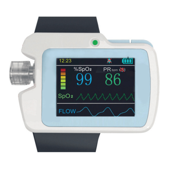
Page 8: Instructions For Front Panel
ENGLISH 3.2 Instructions for Front Panel The measurement interface is showed as Figure3-2-1. Figure 3-2-1 measurement interface The record interface is showed as Figure3-2-2. Figure3-2-2 record interface (1) SpO value display Indicator: %SpO Instruction: Put the finger into the SpO probe,and the corresponding SpO value will be displayed here. - Page 9 ENGLISH (2) Pulse rate value display Indicator: PRbpm Instruction: Put the finger into the SpO probe,and the corresponding pulse rate value will be displayed here. (3) Bar graph display Indicator: Instruction: Put the finger into the SpO probe, and pulse beat will be displayed here.
-
Page 10: Device Operation Explanation
ENGLISH 4 Device Operation Explanation 4.1 Button Operation Power on / Power off / Awake button: Powering on operation: Long press the button , then the green indicator light is on, LOGO is displayed and enter the measurement interface. Powering off operation: Long press the button without recording, the screen displays “Bye-Bye!”, and then the work indicator light is off. - Page 11 ENGLISH Record Record setup, long press “M” button to access record setup menu. DEMO Long press “M” button to enter DEMO interface. Clock Time setup, long press “M” button to access time setup menu. Exit Exit to the measurement interface. Table 4-2-1 4.2.2 Alarm Setup Alarm setup menu is showed as Figure 4-2-2.
- Page 12 ENGLISH With alarm function on, when measurement value exceeds limit, the device gives audio prompt. With pulse sound on, it will give pulse prompt. 4.2.3 System Setup System setup menu is showed as Figure 4-2-3. Figure 4-2-3 System setup menu Callout Function Instruction...
- Page 13 ENGLISH Callout Function Instruction Set Month Month setup, 1~12 can be selected. Set Day Day setup, 1~31 can be selected. Set Hour Hour setup, 0~23 can be selected. Set Minute Minute setup, 0~59 can be selected. Record Record duration setup, 1~10 can be selected and default is 8, unit:hour.
- Page 14 ENGLISH Note: In record status, the interface prompts “TF Card is full!”, it indicates the remain- ing capacity of SD card is lack and the user shall not do record operation. And the user needs to displace previous cases by computer. Manual power off can not be performed in record status, please stop recording before power off.
-
Page 15: Sensor Connection
ENGLISH 4.2.7 Time Setup Time setup menu is showed as Figure 4-2-7. Figure 4-2-7 Time setup menu Callout Function Instruction Set Year Year setup, 2010~2099 can be selected. Set Month Month setup, 1~12 can be selected. Set Day Day setup, 1~31 can be selected. Set Hour Hour setup, 0~23 can be selected. - Page 16 ENGLISH The method of wearing the Nasal cannula is as showed in Figure 4-3-1-2, and that of the entire sensor wearing is as Figure 4-3-1-3. Figure 4-3-1-1 Interface icon Correct Wrong Figure 4-3-1-2 Wearing Nasal cannula...
- Page 17 ENGLISH Figure 4-3-1-3 The entire wearing of sensor Note: Wear the Nasal cannula according to the regulations, or it will affect the gath- ering effect. 4.3.2 SpO and Pulse Rate Monitoring The scheme of the following three probe could be chose by user, as table 4-3-2. Appellation Quantity Scheme...
- Page 18 ENGLISH Figure 4-3-2-3 Binding SpO probe Figure 4-3-2-4 Placing SpO probe Plug the SpO probe into USB interface, as Figure 4-3-2-4. 1) Connect the probe with the device. 2) Put the finger into the probe. 3) In measurement interface,you can directly read corresponding data from dis- play screen.
-
Page 19: Clinical Restrictions
ENGLISH Excessive ambient light may affect the measuring result,including fluorescent lamp, dual ruby light, infrared heater, direct sunlight and etc. There should not be such light barrier as rubber fabric on the way of light, or it may result in incorrect measure results of SpO and pulse rate. -
Page 20: Time Powering On Function
ENGLISH Nasal cannula Warning: Shock,conk patient shall be monitored directed by medical stuff or professional paramedics. 4.5 Time Powering on Function (Refer to 4.2.4 Time powering on setup) After having set up the time for powering on,you can power off, and when the clock arrives to the time set,the device will power on automatically and save. -
Page 21: Charging Operation
ENGLISH Analysis Figure 4-6-3 Connection between PC and the device 1. USB data line 2. The device 3. PC Notes: Data can not be uploaded during recording. To upload data, please stop re- cording. If the computer can not identify the disk symbol, connect USB data line repeat- edly. -
Page 22: Pc Software Operation Explanation
ENGLISH 5 PC Software Operation Explanation Double click Shortcuts to enter the operation system (hereinafter referred as “this system”) as shown in Figure 5-1. Figure 5-1 5.1 Data Importing and Case Management 1: Import Case Data Startup this software and import data. Click “Import Case Data” in “File” menu, then the following Figure 5-1-1 will appears: Figure 5-1-1 Click the button “Open”, then the data importing interface appears, as Figure... - Page 23 ENGLISH Figure 5-1-2 Figure 5-1-3 2. Case Management Click “Case Manage” in “File” menu to its sub-menu as Figure 5-1-4:...
- Page 24 ENGLISH Figure 5-1-4 The left of the interface are all cases in the case library. When selecting any case, the relative patient information will display on the right of the interface, including patient’s basic information and gathered information, you also can add the name of the physician, recorder, and the marks the doctor made.
-
Page 25: System Setting
ENGLISH 5.2 System Setting Select “Global Setting” in “Setting” menu, the global setting dialogue box will pop up as shown in Figure 5-2-1. Figure 5-2-1 1) Fill in the basic hospital information in the “Hospital Info” interface. 2) Set the waveform color or the waveform state of each lead in “Channel setting” interface, as shown in Figure 5-2-2: Figure 5-2-2... - Page 26 ENGLISH 3) There are two interfaces (SpO and flow) in “Param Setting”, you can set up the parameter value in the respective interface (as Figure 5-2-3). Figure 5-2-3 4) You can add, edit and delete marks in “Mark” interface, as shown in Figure 5-2-4: Figure 5-2-4...
- Page 27 ENGLISH Click “Add” to enter “Add Mark” dialogue box (as Figure 5-2-5). Click “OK”, the new mark will display in the mark list. If you want to edit some mark, first, select mark name in the mark list, click “Edit” or double click mark name, the “Edit Mark” dialogue box will appear (as Figure 5-2-6).
-
Page 28: Waveform Display
ENGLISH Figure 5-2-7 When clicking “OK” button in “Global Setting” dialogue box, the setup you have done will be saved in system setting. 5.3 Waveform Display The waveform display area is shown in Figure 5-1-3, the display area can display two waveform charts, or one event chart and one waveform chart, or only event or waveform chart. - Page 29 ENGLISH Figure 5-3-2 The buttons on the right of the waveform display area are showed in Figure 5-3-3, here, you can adjust the size and the baseline position of the waveform. When clicking , the amplitude will get bigger; when clicking , the amplitude will get smaller;...
- Page 30 ENGLISH Drag the mouse on some waveform while clicking the right button and the mark dia- logue box in Figure 5-3-4 will pop up, select the mark type, click “OK” to mark in corre- sponding position (as Figure 5-1-3(2)), put the mouse on the borderline of the marked area, when the editing sign occurs, you can drag the mouse to adjust the marked area size.
-
Page 31: Function Menus
ENGLISH Figure 5-3-6 The buttons for browsing events are showed as Figure 5-3-7, you can select the event name you want to browse in the list, click the left and right arrowhead but- tons to browse the event marks one by one, which is convenient for observing. If there is no suited mark event, this system will give prompt. - Page 32 ENGLISH Figure 5-4-2 3. There are two menu options in the “View” menu, “Report View” and “EventList View” (as Figure 5-4-3). “Report View” menu is used to print reports, when clicking this option, the print preview interface will appear as Figure 5-4-4: there are such functions as zooming in, zooming out and paging-up and paging-down functions, when all have been done, click “Print”...
- Page 33 ENGLISH It also has such functions as editing the diagnosis information and filling it into the report, click “Diagnose” and the Diagnose info interface will appear, as Figure 5-4-5, then you can fill in the diagnosis information and report name. Click “OK” to fill the report name and diagnosis information into the report.
- Page 34 ENGLISH Figure 5-4-6 5. Click “Reanalyse”, the dialogue box as Figure 5-4-7 will appear, click “OK”, you will remove the old data and reanalyse; click “No” to reanalyse but not remove the manual analyse data; click “Cancel” to cancel the reanalyse operation. Figure 5-4-7 6.
-
Page 35: Product Specification
ENGLISH Figure 5-4-8 7. Click “Help”, and the help document of this software will appear. 6 Product Specification Product name: Sleep apnea screen meter Safety: complied with the standard IEC 60601-1 Classification: Compatibility: Group I,Type B Power type: internal powered equipment The degree of protection against electric shock: BF applied part. -
Page 36: Cleaning, Disinfection And Maintenance
ENGLISH Environment temperature range: - 40°C~+55°C Relative humidity range: ≤95 % Atmospheric pressure range: 500 hPa~1060 hPa (2) Operation: Environment temperature range: 10°C~40°C Relative humidity range: ≤75% Atmospheric pressure range: 700 hPa~1060 hPa Battery type: 3.7V Chargeable lithium battery Operation voltage: 3.6 V DC ~ 4.2V DC. Operation current: :≤100 mA Display screen: LCD display screen Performance parameters... -
Page 37: Disinfection
ENGLISH The temperature of the device cleaning water is below 60°C. Never permit any liquid run into the device,nor submerge the device into any liquid. Never spoil liquid on the device when cleaning. Never remain any solution on the surface of the device. 7.2 Disinfection After cleaning the device with the methods above, disinfect it with medical alco- hol, then air-dry (or with dry cloth). -
Page 38: Symbol Meanings
ENGLISH 8 Symbol Meanings Symbol Meaning Follow instructions for use % SpO value (unit: %) PR bpm Pulse rate (unit: bpm) Full power Leak power Audio prompt off Audio prompt on Pulse sound off Pulse sound on • Record indicator Type BF applied part WEEE disposal USB data connection... - Page 39 ENGLISH Symbol Meaning Humidity limitation Disposable device, do not re-use Product code Lot number Serial number Caution: read instructions (warnings) carefully Manufacturer Authorized representative in the European community Date of manufacture Keep in a cool, dry place Keep away from sunlight Fragile, handle with care IP22 Covering Protection rate...
-
Page 40: Trouble Shootings
ENGLISH 9 Trouble Shootings Trouble Possible cause Solution or Pulse rate is 1.The finger is not put in cor- 1.Try again with the finger displayed abnormally. rectly. correctly put in. 2.Patient SpO value is beyond 2.Try repeatedly,if you are the measurement range. sure the product perfor- 3.The deepness of the finger mance is normal,go to... - Page 41 Guidance and manufacturer’s declaration – electromagnetic emission The RS01 is intended for use in the electromagnetic environment specified below. The customer of the user of the RS01 should assure that it is used in such and environment. Emission test Compliance Electromagnetic environment –...
- Page 42 Guidance and manufacturer’s declaration – electromagnetic immunity The RS01 is intended for use in the electromagnetic environment specified below. The customer or the user of RS01 should assure that it is used in such an environment. Immunity test IEC 60601...
- Page 43 RF transmitters, an electromagnetic site survey should be considered. If the measured field strength in the location in which the RS01 is used exceeds the applicable RF compliance level above, the RS01 should be observed to verify normal operation. If ab- normal performance is observed, additional measures may be necessary, such as reorienting or relocating the RS01.
- Page 44 Congratulations for purchasing a GIMA product. This product meets high qualita- tive standards both as regards the material and the production. The warranty is valid for 12 months from the date of supply of GIMA. During the period of validity of the warranty, GIMA will repair and/or replace free of charge all the defected parts due to production reasons.
Need help?
Do you have a question about the RS01 and is the answer not in the manual?
Questions and answers