
Related Manuals for AVPro Edge AC-EX70-UHD-KIT


Summary of Contents for AVPro Edge AC-EX70-UHD-KIT
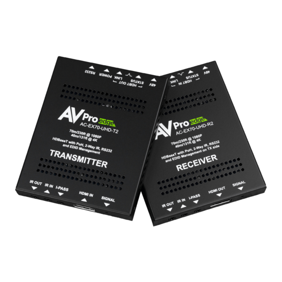
- Page 1 USER MANUAL Ultra Slim 70 Meter HDMI Via HDBaseT Extender Set with Bi-Directional Power and EDID Management AC-EX70-UHD-KIT...
-
Page 2: Table Of Contents
Table of Contents T A B L E O F C O N T E N T S � � � � � � � � � � � � � � � � � � � � � � � � � � � � � � � � � � � � � � � � � � � � � � � � � � � � � � � � � � � � � � � � � � � � 2 I N T R O D U C T I O N �... -
Page 3: Introduction
Introduction The AVPro Edge primary extender is the most cost effective, state of the art, and reliable single CAT 70 meter extender on the market today. It solves problems for both commercial and residential markets for distributing high value 4K UHD content from rack to display. -
Page 4: Specifications
Specifications... -
Page 5: Transmitter Overview
Transmitter Overview EDID DIP Switches see page 12 HDBaseT RS-232 IR IN HDMI Input 48V Power Power LED RS-232 Operation Mode Switch IR OUT I-PASS HDMI Signal Indicator LED Indicator Troubleshooting Lights - Transmitter POWER - On the back by power HDBaseT RJ45 port: (Red) This is an indicator that the power is connected. - Page 6 If the BLUE HDMI SIGNAL LIGHT is flashing, check the following: · The source. Plug it directly into the display to be sure it’s functioning properly. · Try a longer HDMI cable. Some HDMI cables do not sync well at shorter lengths, a 2 meter minimum is recommended per HDMI Specifications.
- Page 7 Status above the RJ45 (HDBaseT) Port: (Amber) This indicator shows that theres power present between the Tx and Rx. This light blink steadily indicating everything is OK. If you do not see this light attempt the following: · Check the length. The maximum distances are 40m (131ft) on 4K and 70m (230ft) on 1080P.
- Page 8 Powering the System Bi-Directional Power: The AC-EX70-UHD-KIT allows you to choose where you power the kit. There are two options: · Powering at the HDBaseT Tx - The power will be supplied to the Rx through the CAT cable. · Powering at the HDBaseT Rx - The power will be supplied to the Tx through the CAT Cable (This is known as “Reverse Power)
-
Page 9: Receiver Overview
Receiver Overview HDBaseT RS-232 48V Power Power LED RS-232 Operation Mode Switch IR IN HDMI Out put IR OUT I-PASS HDMI Signal Indicator LED Indicator Troubleshooting Lights - Receiver POWER - On the back by power HDBaseT RJ45 port: (Red) This is an indicator that the power is connected. -
Page 10: I R C O N F I G U R A T I O
IR Configuration There are three different 3.5mm IR ports located on the Transmitter and Receiver. IR OUT - This port is designed to accept an IR Emitter In the example below an IR receiving eye is plugged into the “IR IN” port of the HDBaseT Transmit- ter, and a IR Emitter is plugged into the “IR OUT”... - Page 11 IR IN - This port is designed to accept an IR Receiving Eye/Sensor IPASS - This port is designed to be directly connected to a control system via a 3.5mm Mono cable NOTE: IPASS is only an INPUT. So you can go IPASS in from a control system to IR OUT. Control System >...
-
Page 12: E D I D M A N A G E M E N T - T R A N S M I T T E
EDID Management - Transmitter Default out of the box all the dip switches are down (off) “BYPASS (HDBT)”mode. This will pass the EDID of the connected display to the source un-altered. NOTE: This is a 10.2Gbps extender, when in “BYPASS (HDBT)”make sure the source is not sending a signal that exceeds this HDBaseT Extender set�... -
Page 13: R S - 2 3 2 C O N F I G U R A T I O
RS-232 Configuration For extending RS-232 communication over the Category cable. For these to pass a signal, both the Transmitter and Receiver need to have the Dip Switch set to Normal Mode, not RS-232 Program. Default out of the box is MODE NORM (Normal Mode). RS232 PROG (Program mode for Firmware updating). -
Page 14: T R O U B L E S H O O T I N
Troubleshooting · Verify Power - Check that the power supply is properly connected and on an active circuit. · Verify Connections - Check that all cables are properly connected. · TX/RX Indicator Troubleshooting Lights - Pg. 5-6 · IR Issues - Verify correct connections - P. 8-9 Note: Visibly flashing Emitters may not function properly, if you are experiencing issue try the IR Cables that come in the box. -
Page 15: M A I N T E N A N C
Maintenance To ensure reliable operation of this product as well as protecting the safety of any person using or handling this device while powered, please observe the following instructions. · Use the power supplies provided. If an alternate supply is required, check voltage, polarity and that it has sufficient power to supply the device it is connected to. -
Page 16: S U P P O R
Support Should you experience any problems while using this product, first, refer to the Troubleshooting section of this manual before contacting Technical Support. When calling, the following information should be provided: · Product name and model number · Product serial number ·... - Page 19 Thank you for choosing AVProEdge! Please contact us with any questions, we are happily at your service! AVProEdge 2222 E 52nd St N ~ Sioux Falls, SD 57104 1-877-886-5112 ~ 605-274-6055 support@avproedge.com...
Need help?
Do you have a question about the AC-EX70-UHD-KIT and is the answer not in the manual?
Questions and answers