MacDon DWA Operation And Parts Manual
Double windrow attachment for m1-series self-propelled windrowers
Hide thumbs
Also See for DWA:
- Setup, operation, and parts manual (140 pages) ,
- Operation and parts manual (132 pages)

Related Manuals for MacDon DWA


Summary of Contents for MacDon DWA
- Page 1 Double Windrow Attachment (DWA) for M1-Series Self-Propelled Windrowers Setup, Operation, and Parts Manual 214048 Revision A Model Year 2017 Original Instruction The harvesting specialists.
- Page 2 This instruction contains the setup procedures, operation instructions, and parts lists for the MacDon Double Windrow Attachment (DWA) for M1-Series Self-Propelled Windrowers. Published: September 2016...
- Page 3 • R-Series Rotary Disc Header When the DWA system is engaged, the conditioned crop is deposited onto the side draper and placed to the side of the windrower. Raising the side delivery disengages the DWA, allowing the crop to be deposited between the windrower’s wheels.
- Page 4 Serial Number Location Record the serial number of the Double Windrow Attachment (DWA) in the space provided. DWA serial number: __________________________ The serial number plate is located on the deck (A). Figure 1: Serial Number Location 214048 Revision A...
- Page 5 List of Revisions At MacDon, we’re continuously making improvements: occasionally these improvements impact product documentation. The following list provides an account of major changes from the previous version of this document. Location Summary of Change Updated document introduction with Generic Statement Introduction, page i and revised warranty message.
-
Page 7: Table Of Contents
M1240 Disc-Only Configuration....................18 2.4.2 M1240 Disc- and Draper-Ready Configuration ................. 19 Connecting the Proximity Sensor ....................21 Activating the Double Windrow Attachment (DWA)................22 2.6.1 Setting One-Touch-Return Buttons (A, B, C) ................22 2.6.2 Setting Draper Pressure Alarm....................23 Operation ............................ - Page 8 TABLE OF CONTENTS Hydraulic Schematic ........................51 Repair Parts ............................53 Deck, Draper, and Rollers ......................54 Linkage and Deck Support ......................60 Decals and Reflectors ........................66 Reference ............................69 Torque Specifications ........................69 6.1.1 SAE Bolt Torque Specifications ....................69 6.1.2 Metric Bolt Specifications ......................
-
Page 9: Safety
1 Safety 1.1 Safety Alert Symbols This safety alert symbol indicates important safety messages in this manual and on safety signs on the machine. This symbol means: • ATTENTION! • BECOME ALERT! • YOUR SAFETY IS INVOLVED! Carefully read follow safety message accompanying this symbol. -
Page 10: Signal Words
SAFETY 1.2 Signal Words Three signal words, DANGER, WARNING, and CAUTION, are used to alert you to hazardous situations. The appropriate signal word for each situation has been selected using the following guidelines: DANGER Indicates an imminently hazardous situation that, if not avoided, will result in death or serious injury. WARNING Indicates a potentially hazardous situation that, if not avoided, could result in death or serious injury. -
Page 11: General Safety
SAFETY 1.3 General Safety CAUTION The following are general farm safety precautions that should be part of your operating procedure for all types of machinery. Protect yourself. • When assembling, operating, and servicing machinery, wear all protective clothing and personal safety devices that could be necessary for job at hand. - Page 12 SAFETY • Wear close-fitting clothing and cover long hair. Never wear dangling items such as scarves or bracelets. • Keep all shields in place. NEVER alter or remove safety equipment. Make sure driveline guards can rotate independently of shaft and can telescope freely. •...
-
Page 13: Maintenance Safety
SAFETY 1.4 Maintenance Safety To ensure your safety while maintaining machine: • Review operator’s manual and all safety items before operation and/or maintenance of machine. • Place all controls in Neutral, stop engine, set park brake, remove ignition key, and wait for all moving parts to stop before servicing, adjusting, and/or repairing. -
Page 14: Hydraulic Safety
SAFETY 1.5 Hydraulic Safety • Always place hydraulic controls Neutral before dismounting. • Make sure that all components in hydraulic system are kept clean and in good condition. • Replace any worn, cut, abraded, flattened, or crimped hoses and steel lines. •... -
Page 15: Safety Signs
Dealer Parts Department. • Safety signs are available from your MacDon Dealer. Figure 1.14: Operator’s Manual Decal 1.6.1 Installing Safety Decals 1. Clean and dry installation area. 2. Decide on exact location before you remove decal backing paper. -
Page 16: Safety Sign Decals
SAFETY 1.7 Safety Sign Decals MD #166466 HIGH PRESSURE HYDRAULICS DO NOT GO NEAR LEAKS Located on deck • High pressure oil easily punctures skin causing serious injury, gangrene or death • If injured, seek emergency medical help. Immediate surgery is required to remove oil •... - Page 17 SAFETY MD #176295 DECK LIFT LOCK Located on deck linkage Figure 1.17: MD #176295 214048 Revision A...
-
Page 19: Assembly/Setup Instructions
Introduction, page 2.1 Raising and Lowering the Right-Hand Stairs The right-hand stairs need to be raised when installing or operating the Double Windrow Attachment (DWA) in either a lowered or raised position. To raise and lock the stairs follow these steps: 1. -
Page 20: Installing The Linkage
To install the linkage on a M1240 windrower, follow these steps: 1. Remove four bolts (A), two washers (B) and two nuts (C) that are loosely installed on the DWA linkage. Keep hardware for mounting. Figure 2.3: Linkage Support 2. Support linkage assembly (A) with a forklift (B) and lift into place under windrower. - Page 21 1, page 12) (A) to attach linkage assembly to windrower frame. Torque to 340 ft·lbf (461 N·m). 5. Torque four bolts (B) on DWA linkage to 107–118 ft·lbf (144–160 N·m). Figure 2.6: Linkage Support Under Windrower NOTE: Windrower not shown for clarity.
-
Page 22: Installing The Deck
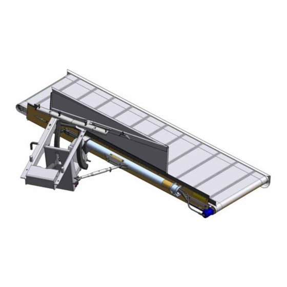
ASSEMBLY/SETUP INSTRUCTIONS 2.3 Installing the Deck To install the DWA deck, follow these steps: 1. Remove the shipping boards (A) by removing the transport banding (B) and discard. Figure 2.9: DWA Deck 2. Support the deck with a forklift. Forks (C) should be inboard of shipping stand (A). - Page 23 6. Remove the shipping stand (A) by removing the transport wire (B). Figure 2.12: Deck Shipping Stand The DWA deck is now ready to be assembled to the linkage underneath the windrower. 7. Position the DWA deck on the right-hand side of the windrower.
- Page 24 ASSEMBLY/SETUP INSTRUCTIONS 9. Position the deck pivot (A) into the linkage clevis (B). NOTE: Make sure there is a loose bushing inside the deck pivot (A). 10. Align the deck pivot (A) with the holes in the clevis (B) by raising or lowering the floor jack, and insert shaft (C) with preinstalled hex nut (D) and lock nut (E) through the top.
- Page 25 ASSEMBLY/SETUP INSTRUCTIONS 15. Adjust the turnbuckle length so the space (A) between the deck and the right-hand drive tire is approximately 100 mm (4 in.). NOTE: The single-acting lift cylinder is pressurized with the draper drive circuit. Therefore, when the deck is set up for the rotary disc headers, the windrower needs to be running for the deck to be in its most forward position.
-
Page 26: Installing The Hydraulics To M1240 Windrower
ASSEMBLY/SETUP INSTRUCTIONS 2.4 Installing the Hydraulics to M1240 Windrower 2.4.1 M1240 Disc-Only Configuration To install the DWA hydraulics to a M1240 Self-Propelled Windrower configured for disc-only headers, follow these steps: Install the DWA linkage hydraulics to windrower. 1. Route hoses (A) underneath both filters as shown. -
Page 27: M1240 Disc- And Draper-Ready Configuration
In addition to the hardware used for connecting to disc headers, an M1240 Self-Propelled Windrower will also have a four point multicoupler installed to allow for connecting to draper headers. To install the DWA hydraulics to a M1240 Self-Propelled Windrower configured for disc- and draper-ready headers, follow these steps: Install the DWA linkage hydraulics to the windrower. - Page 28 ASSEMBLY/SETUP INSTRUCTIONS 4. Connect the hydraulic hose (A) with the blue fastener (MD #135266) (B) to the reducer (C) on the multicoupler bulkhead fitting closest to the windrower. 5. Connect the other hydraulic hose (D) to the remaining reducer (E) on the multicoupler bulkhead fitting. Figure 2.24: Deck Hydraulic Hoses and Multicoupler Connections (Parts Removed for Clarity)
-
Page 29: Connecting The Proximity Sensor
ASSEMBLY/SETUP INSTRUCTIONS 2.5 Connecting the Proximity Sensor To connect the proximity sensor for the Double Windrow Attachment (DWA), follow these steps: NOTE: The proximity sensor comes preinstalled on the DWA linkage. 1. Remove the cable tie binding the DWA extension (A) to the chassis harness (B) from windrower. -
Page 30: Activating The Double Windrow Attachment (Dwa)
(A). Figure 2.26: Header Setup – Attachments 2. Select DWA and the display will show an image of the buttons to be used to control the DWA with each particular header. DWA is now activated. -
Page 31: Setting Draper Pressure Alarm
The One-Touch-Return buttons will always save header height settings, but you can also save the following settings for the DWA: • DWA up/down • DWA speed Refer to your windrower operator’s manual for more detailed One-Touch-Return information. - Page 32 ASSEMBLY/SETUP INSTRUCTIONS 2. Scroll to place the red cursor over the DWA draper pressure icon (A). Figure 2.32: QuickMenu / Draper Pressure Alarm 3. Adjust alarm setpoint (B) to desired value by scrolling until the pressure reaches the desired alarm point.
-
Page 33: Operation
3 Operation 3.1 Operational Safety CAUTION To avoid bodily injury: • Review the safety sections of your windrower and header operator’s manuals. • Keep all shields in place. • Engage the deck safety pin when deck is raised fully for transport, service, and storage—or before going under deck for any reason. -
Page 34: Engaging The Deck Safety Pin
3.2 Engaging the Deck Safety Pin Engage the deck safety pin as follows: 1. Raise the Double Windrow Attachment (DWA) deck. 2. Push pin (A) inward until both roll pins (B) are inside the channel. Rotate the pin (A) 90 degrees. -
Page 35: Raising And Lowering The Deck
Adjusting the Proximity Sensor, page DWA raise and lower can be controlled in three ways: 1. Raise and lower the DWA deck by using the reel raise button (A) and the reel lower button (B) respectively on the ground speed lever (GSL). The operator can interrupt the raising and lowering of the deck by letting go of the buttons. -
Page 36: Adjusting The Deck Lift Speed
3.3.1 Adjusting the Deck Lift Speed Finding the proper Double Windrow Attachment (DWA) deck lift speed is essential to its proper operation. The deck must lift fast enough to clear a windrow, and slow enough not to stop abruptly against the bottom of the windrower. -
Page 37: Adjusting The Proximity Sensor
(A) at the linkage needs to be lowered: NOTE: Carefully adjust the proximity sensor when running up the DWA for the first time. 1. Loosen screws (B) to lower the switch. 2. Tighten screws (B) when the adjustment is complete. NOTE: Figure 3.7: Proximity Sensor... -
Page 38: Setting Draper Speed
This means the header may be engaged, but the DWA deck may not be turning. Increase the speed, and check that the deck has started to turn. - Page 39 OPERATION 4. The DWA’s draper speed is displayed on the Harvest Performance Tracker (HPT) as shown. Figure 3.11: Harvest Performance Tracker (HPT) 214048 Revision A...
-
Page 40: Adjusting Deck Angle
NOTE: If set up with an R-Series Rotary Disc Header, the DWA deck will only be in its most forward position when the windrower is running. The lift cylinder is single acting and not pressurized when the windrower is shut off. When the windrower is running, a supply of low pressure oil moves the deck forward. -
Page 41: Adjusting Deck Angle Relative To The Ground
(A) should be equal to distance (B). • If the crop needs to be thrown farther, increase distance (A). Figure 3.15: DWA Deck To adjust deck angle: 1. Loosen the four 3/4 in. bolts (A). 2. Loosen jam nut (C). -
Page 42: Adjusting Deck Height
If the deck is too low to the ground, raise it as follows: 1. Lower linkage by fully extending cylinder. 2. Move bottom pivot pin to lower position (A). This will raise the front of the deck approximately 100 mm (4 in.). Figure 3.17: DWA Linkage 214048 Revision A... -
Page 43: Positioning The Conditioner Forming Shield
Figure 3.19: Forming Shield 3. Adjust the left-hand side deflector (B) to direct crop towards the inboard side of the DWA back sheet (C). NOTE: If center delivering, the left-hand deflector (B) can be moved inward to form a narrower windrow. - Page 44 OPERATION 5. Adjust the rear deflector baffle (A) so crop flow (B) does not interfere with the deck when fully raised. Figure 3.21: Deck Raised NOTE: The fins (B) under the forming shield can interfere with crop flow, especially with an R-Series Header in light crop.
-
Page 45: Positioning The Conditioner Rolls
OPERATION 3.8 Positioning the Conditioner Rolls The gap between the conditioner rolls needs to be small enough to properly throw the crop onto the Double Windrow Attachment. The gap size depends on the crop type and yield. • A gap that is too small for a heavy crop will use excessive engine power and be hard on affected components. •... -
Page 46: Operating Recommendations
Adjust the position of a side delivered crop by varying the draper speed. • When using 25- and 30-foot headers on heavy crop, double windrowing may not be desired. Raise the DWA deck to lay single windrows between the windrower’s wheels. -
Page 47: Operating With An R-Series Rotary Disc Header
• It may be possible to shoot crop above the forming shield with extreme header angle and rear baffle positions. • In rocky conditions where a DWA is necessary, a high skid shoe kit or adjustment to gauge rollers may be required to achieve correct stubble height while maintaining proper crop trajectory. -
Page 49: Maintenance And Servicing
4 Maintenance and Servicing 4.1 Draper Maintenance 4.1.1 Adjusting Draper Tension Adjust the draper tension enough to prevent slipping and eliminate sagging. Set draper tension as follows: 1. Check that draper guide (rubber track on underside of draper) is properly engaged in groove of drive roller, and that idler roller is between the guides. - Page 50 MAINTENANCE AND SERVICING Table 4.1 Draper Tracking Adjustments Tracking At Location Adjustment Method Rearward Move roller (A) outward Tighten nut (B) Idler roller Forward Move roller (A) inward Loosen nut (B) Rearward Move roller (C) outward Tighten nut (D) Drive roller Forward Move roller (C) inward Loosen nut (D)
-
Page 51: Replacing Draper
MAINTENANCE AND SERVICING To adjust tracking on the drive roller side: 1. Loosen the three locking nuts (A). 2. Adjust nut (D) according to Table 4.1 Draper Tracking Adjustments, page 3. Tighten the three nuts (A) to secure the drive roller. 4. -
Page 52: Adjusting Front Skid
MAINTENANCE AND SERVICING 4.1.5 Adjusting Front Skid To adjust the front skid (A) follow these steps: 1. Loosen five nuts (B) on the front of the skid. Figure 4.6: Draper Deck Front Skid 2. Adjust the front skid (A) so skid height (C) is 1.5–3 mm (1/16–1/8 in.) above the draper. -
Page 53: Adjusting Rear Deflector
MAINTENANCE AND SERVICING 4.1.6 Adjusting Rear Deflector The rear deflector (A) prevents crop from entering inside draper. To adjust the rear deflector, follow these steps: 1. Loosen all eight nuts (B) along the length of the deck. 2. Set the deflector height (C) to be 1.5–8 mm (1/16–5/16 in.) above the draper. - Page 54 MAINTENANCE AND SERVICING To remove the drive roller from the deck, follow these steps: 1. Raise deck, and engage safety pin (A). 2. Remove front skid, loosen and remove draper. Refer 4.1.5 Adjusting Front Skid, page Figure 4.9: Safety Pin 3.
-
Page 55: Removing And Reinstalling The Idler Roller
MAINTENANCE AND SERVICING To reinstall the drive roller on the deck, follow these steps: 1. Slide the drive roller onto the motor shaft. Make sure it is fully engaged. NOTE: The drive roller should be 33 mm (1-1/3 in.) (A) from the face of the motor. -
Page 56: Replacing Draper Roller Bearing/Seal
MAINTENANCE AND SERVICING To remove the idler roller follow these steps: 1. Raise the deck and engage the safety pin (A). 2. Remove the front skid. Refer to 4.1.5 Adjusting Front Skid, page Figure 4.15: Safety Pin 3. Loosen the draper. NOTE: Draper does not need to be removed, but removal will ease roller disassembly. - Page 57 MAINTENANCE AND SERVICING 2. Remove bearing assembly (B) and seal (A) from roller tube (C) as follows: a. Attach a slide hammer (D) to threaded shaft. b. Tap out the bearing assembly. 3. Clean inside the roller tube (C) and check for wear or damage.
-
Page 58: Lubrication
MAINTENANCE AND SERVICING 4.2 Lubrication Grease the following five pivot points (A) every 250 hours and/or at the end of each season. Figure 4.20: Deck Pivot Figure 4.21: Linkage Pivot Figure 4.22: Linkage Pivot: Bottom View of DWA 214048 Revision A... -
Page 59: Hydraulic Schematic
MAINTENANCE AND SERVICING 4.3 Hydraulic Schematic For detailed hydraulic schematics, refer to your windrower technical manual. Figure 4.23: DWA Hydraulic Schematic A - Lift Manifold B - DWA Drive Motor D - Hydraulic Tank C - DWA Lift Cylinder E - Hydraulic Filter Element... -
Page 61: Repair Parts
5 Repair Parts This section lists all the replacement parts that can be ordered for a Double Windrow Attachment (DWA) for M1-Series Self-Propelled Windrowers. When ordering, be sure the complete and proper part number is given. 214048 Revision A... -
Page 62: Deck, Draper, And Rollers
REPAIR PARTS 5.1 Deck, Draper, and Rollers 214048 Revision A... - Page 63 REPAIR PARTS Part Serial Number Description Number 172730 DECK – C/W DECALS 144833 ROLLER – IDLER WELDT 176000 ARM SUPPORT WELDT FRONT 144837 ARM SUPPORT REAR 165735 PIN ASSY – DRAPER ROLLER 132607 BEARING – DOUBLE ROW BALL 52 OD X 25 BORE 120845 SEAL –...
- Page 64 REPAIR PARTS 214048 Revision A...
- Page 65 REPAIR PARTS Part Serial Number Description Number 18671 FITTING – LUBE 1/4 - 28 UNF 176063 SHAFT 184461 FITTING – ADAPTER 10 MORFS X 10 MORB 176534 HOSE – HYDRAULIC 135266 FASTENER – CABLE TIE (LIGHT BLUE) 136458 FITTING – ELBOW 45° HYD (M1240 ONLY) 145361 NUT –...
- Page 66 REPAIR PARTS 214048 Revision A...
- Page 67 REPAIR PARTS Part Serial Number Description Number 50186 NUT – FLANGE LOCK SM FACE DT 0.500-13 UNC GR5 135157 SCREW – MACHINE 135906 BOLT – HH 5/8 NC X 7.5 LG TFL GR 5 ZP 135966 BOLT – HH FLG (SM FACE) 3/8 NC X 1.0 GR5 ZP 137727 NUT –...
-
Page 68: Linkage And Deck Support
REPAIR PARTS 5.2 Linkage and Deck Support 214048 Revision A... - Page 69 SHAFT – 25 MM OD, 420 MM LG 176016 PIN – L 176023 SHAFT – 25 MM OD, 420 MM LG 176540 SUPPORT – DWA PROXIMITY SWITCH 200974 SWITCH – PROXIMITY, C/W SPACERS 176462 SUPPORT – FRONT WELDT 176509 SUPPORT – REAR WELDT, DWA...
- Page 70 REPAIR PARTS 214048 Revision A...
- Page 71 REPAIR PARTS Serial Part Number Description Number 135781 FITTING – ADAPTER 44209 O-RING – #8 ORB 135867 O-RING – #10 ORFS 136149 FITTING – ELBOW 90° HYD C/W O-RINGS 50219 O-RING – #6 ORB 135865 O-RING – #12 ORB 136147 FITTING –...
- Page 72 REPAIR PARTS 214048 Revision A...
- Page 73 REPAIR PARTS Serial Part Number Description Number 50163 BOLT – HH 5/8 NC X 5.5 LG GR5 ZP 18600 WASHER – SAE FLAT 21/32 ID X 15/16 IN OD ZP 50225 NUT – FLANGE DT SMOOTH FACE .625-11 UNC 136133 BOLT –...
-
Page 74: Decals And Reflectors
REPAIR PARTS 5.3 Decals and Reflectors 214048 Revision A... - Page 75 220084 DECAL – DRAPER TENSION 166466 DECAL – WARNING, HIGH PRESSURE HYDRAULICS 176295 DECAL – DECK LIFT LOCK 174683 DECAL – WARNING DWA LINKAGE PINCH POINT 115145 REFLECTOR – FLUORESCENT RED-ORANGE 115146 REFLECTOR – AMBER 115147 REFLECTOR – RED 214048...
-
Page 77: Reference
6 Reference 6.1 Torque Specifications The following tables provide correct torque values for various bolts, cap screws, and hydraulic fittings. • Tighten all bolts to torque values specified in charts (unless otherwise noted throughout this manual). • Replace hardware with same strength and grade of bolt. •... - Page 78 REFERENCE Table 6.2 SAE Grade 5 Bolt and Grade F Distorted Thread Nut Torque (ft·lbf) Torque (N·m) Nominal (*in·lbf) Size (A) Min. Max. Min. Max. 1/4-20 5/16-18 16.7 18.5 *149 *164 3/8-16 7/16-14 1/2-13 9/16-12 Figure 6.2: Bolt Grades 5/8-11 A - Nominal Size B - SAE-8 C - SAE-5...
-
Page 79: Metric Bolt Specifications
REFERENCE Table 6.4 SAE Grade 8 Bolt and Grade 8 Free Spinning Nut Torque (ft·lbf) Torque (N·m) Nominal (*in·lbf) Size (A) Min. Max. Min. Max. 1/4-20 16.8 18.6 *150 *165 5/16-18 3/8-16 7/16-14 1/2-13 9/16-12 Figure 6.4: Bolt Grades 5/8-11 A - Nominal Size B - SAE-8 C - SAE-5... - Page 80 REFERENCE Table 6.6 Metric Class 8.8 Bolts and Class 9 Distorted Thread Nut Torque (ft·lbf) Torque (N·m) Nominal (*in·lbf) Size (A) Min. Max. Min. Max. 3-0.5 3.5-0.6 4-0.7 5-0.8 6-1.0 8-1.25 18.8 20.8 *167 *185 Figure 6.6: Bolt Grades 10-1.5 12-1.75 14-2.0 16-2.0...
- Page 81 REFERENCE Table 6.8 Metric Class 10.9 Bolts and Class 10 Distorted Thread Nut Torque (ft·lbf) Torque (N·m) Nominal (*in·lbf) Size (A) Min. Max. Min. Max. 3-0.5 3.5-0.6 4-0.7 5-0.8 6-1.0 10.7 11.8 *105 8-1.25 Figure 6.8: Bolt Grades 10-1.5 12-1.75 14-2.0 16-2.0 20-2.5...
-
Page 82: Metric Bolt Specifications Bolting Into Cast Aluminum
REFERENCE 6.1.3 Metric Bolt Specifications Bolting into Cast Aluminum Table 6.9 Metric Bolt Bolting into Cast Aluminum Bolt Torque Nominal 10.9 Size (A) (Cast Aluminum) (Cast Aluminum) N·m N·m ft·lbf ft·lbf – – – – – – – Figure 6.9: Bolt Grades –... - Page 83 REFERENCE Table 6.10 Flare-Type Hydraulic Tube Fittings Torque Value Flats from Finger Tight (FFFT) SAE Dash Size Thread Size (in.) Swivel Nut or N·m ft·lbf Tube Hose — — 5/16–24 4–5 3–4 — — 3/8–24 7–8 5–6 7/16–20 18–19 13–14 2-1/2 1/2–20 19–21...
-
Page 84: O-Ring Boss (Orb) Hydraulic Fittings (Adjustable)
REFERENCE 6.1.5 O-Ring Boss (ORB) Hydraulic Fittings (Adjustable) 1. Inspect O-ring (A) and seat (B) for dirt or obvious defects. 2. Back off lock nut (C) as far as possible. Ensure that washer (D) is loose and is pushed toward lock nut (C) as far as possible. - Page 85 REFERENCE Table 6.11 O-Ring Boss (ORB) Hydraulic Fittings (Adjustable) Torque Value SAE Dash Size Thread Size (in.) N·m ft·lbf (*in·lbf) 5/16–24 6–7 *53–62 3/8–24 12–13 *106–115 7/16–20 19–21 14–15 1/2–20 21–33 15–24 9/16–18 26–29 19–21 3/4–16 46–50 34–37 7/8–14 75–82 55–60 1-1/16–12 120–132...
-
Page 86: O-Ring Boss (Orb) Hydraulic Fittings (Non-Adjustable)
REFERENCE 6.1.6 O-Ring Boss (ORB) Hydraulic Fittings (Non-Adjustable) 1. Inspect O-ring (A) and seat (B) for dirt or obvious defects. 2. Check that O-ring (A) is NOT on threads and adjust if necessary. 3. Apply hydraulic system oil to O-ring. 4. -
Page 87: O-Ring Face Seal (Orfs) Hydraulic Fittings
REFERENCE 6.1.7 O-Ring Face Seal (ORFS) Hydraulic Fittings 1. Check components to ensure that sealing surfaces and fitting threads are free of burrs, nicks, scratches, or any foreign material. Figure 6.14: Hydraulic Fitting 2. Apply hydraulic system oil to O-ring (B). 3. - Page 88 REFERENCE Table 6.13 O-Ring Face Seal (ORFS) Hydraulic Fittings Torque Value SAE Dash Size Thread Size (in.) Tube O.D. (in.) N·m ft·lbf Note 3/16 – – 9/16 25–28 18–21 Note – – 5/16 11/16 40–44 29–32 13/16 55–61 41–45 80–88 59–65 1-3/16 115–127...
-
Page 89: Tapered Pipe Thread Fittings
REFERENCE 6.1.8 Tapered Pipe Thread Fittings Assemble pipe fittings as follows: 1. Check components to ensure that fitting and port threads are free of burrs, nicks and scratches, or any form of contamination. 2. Apply pipe thread sealant (paste type) to external pipe threads. 3. -
Page 90: Conversion Chart
REFERENCE 6.2 Conversion Chart Table 6.15 Conversion Chart SI Units (Metric) Inch-Pound Units Quantity Factor Unit Name Abbreviation Unit Name Abbreviation Area hectares x 0.4047 = acres acres US gallons Flow liters per minute L/min x 3.7854 = per minute Force Newtons x 4.4482 =... -
Page 91: Index
Index 2147 ..............61 132532 ............... 55 11695 ..............57 132607 ............... 55 16266 ..............61 135157 ............... 59 18589 ............57, 63 135266 ............... 57 18590 ..............57 135312 ............... 63 18592 ..............63 135386 ............... 63 18593 ..............57 135778 ............... - Page 92 220084 ............... 67 220181 ............... 55 Harvest Performance Tracker (HPT) 252183 ............... 63 activating ............22 252525 ............... 57 double windrower attachment (DWA) ..... 22 One-Touch-Return buttons (A, B, C) ....22 setting pressure/speed alarms......23 hydraulics fittings assembly/setup ..........11, 21 flare-type ............
- Page 93 INDEX lubrication ............50 predelivery checklist ..........87 proximity sensor ..........21 maintenance safety ..............5 repair parts maintenance and servicing ........41 decals and reflectors ........66 draper.............. 41 deck, draper, and rollers ........54 adjusting draper tension ........ 41 linkage and deck support ........
-
Page 95: Predelivery Checklist
Carefully follow the instructions given. Be alert for safety related messages that bring your attention to hazards and unsafe practices. DWA Serial Number: Table 1 DWA for M1–Series Self-Propelled Windrower Predelivery Checklist Item Reference Check for shipping damage or missing parts. Be sure all —... - Page 98 10708 N. Pomona Avenue Kansas City, Missouri United States 64153-1924 t. (816) 891-7313 f. (816) 891-7323 MacDon Australia Pty. Ltd. A.C.N. 079 393 721 P.O. Box 243, Suite 3, 143 Main Street Greensborough, Victoria, Australia 3088 t. 03 9432 9982 f.
Need help?
Do you have a question about the DWA and is the answer not in the manual?
Questions and answers