MacDon DWA Setup, Operation, And Parts Manual
Double windrow attachment for m series self-propelled windrowers
Hide thumbs
Also See for DWA:
- Operation and parts manual (98 pages) ,
- Operation and parts manual (132 pages)

Subscribe to Our Youtube Channel
Related Manuals for MacDon DWA


Summary of Contents for MacDon DWA
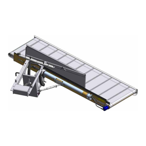
- Page 1 Double Windrow Attachment (DWA) for M Series Self-Propelled Windrowers Setup, Operation, and Parts Manual 215626 Revision A Original Instruction The Harvesting Specialists.
- Page 2 © 2021 MacDon Industries, Ltd. The information in this publication is based on the information available and in effect at the time of printing. MacDon Industries, Ltd. makes no representation or warranty of any kind, whether expressed or implied, with respect to the...
- Page 3 The DWA can be mounted on M150, M155, M155E4, M200, and M205 Self-Propelled Windrowers. The DWA is for use with A Series Auger Headers, D Series Draper Headers with HC10 Hay Conditioners, and R Series Rotary Disc Headers.
- Page 4 NOTE: If parts are damaged or missing from the DWA installation kit, contact shortageanddamage@macdon.com. 215626 Revision A...
- Page 5 Summary of Changes At MacDon, we’re continuously making improvements: occasionally these improvements impact product documentation. The following list provides an account of major changes from the previous version of this document. Section Summary of Change Internal Use Only Introduction, page i Added a short shipment advisory.
-
Page 6: Serial Number Location
Serial Number Location Record the serial number and model year of the Double Windrow Attachment (DWA) in the spaces provided. DWA serial number: __________________________ The serial number plate is located on the deck (A). DWA model year: __________________________ Figure 1: Serial Number Location... -
Page 7: Table Of Contents
TABLE OF CONTENTS Introduction ..............................i Summary of Changes........................... iii Serial Number Location ..........................iv Chapter 1: Safety ............................1 1.1 Safety Alert Symbols ..........................1 1.2 Signal Words ............................2 1.3 General Safety ............................3 1.4 Maintenance Safety ..........................5 1.5 Hydraulic Safety .............................6 1.6 Safety Signs ............................7 1.6.1 Installing Safety Decals........................7 1.7 Safety Sign Decals...........................8... - Page 8 TABLE OF CONTENTS Chapter 3: Operation..........................57 3.1 Operational Safety..........................57 3.2 Engaging Deck Safety Pin ........................58 3.3 Raising and Lowering Deck ........................59 3.3.1 Adjusting Deck Lift Speed ......................60 3.3.2 Adjusting Draper Shut-Off Switch....................60 3.4 Setting Draper Speed ..........................61 3.5 Adjusting the Deck Angle ........................
- Page 9 TABLE OF CONTENTS 6.1.1 SAE Bolt Torque Specifications ..................... 109 6.1.2 Metric Bolt Specifications ......................111 6.1.3 Metric Bolt Specifications Bolting into Cast Aluminum ..............113 6.1.4 Flare-Type Hydraulic Fittings ......................114 6.1.5 O-Ring Boss Hydraulic Fittings – Adjustable ..................115 6.1.6 O-Ring Boss Hydraulic Fittings –...
-
Page 11: Chapter 1: Safety
Chapter 1: Safety Understanding and consistently following these safety procedures will help to ensure the safety of those operating the Double Windrow attachment (DWA) and of bystanders. 1.1 Safety Alert Symbols The safety alert symbol indicates important safety messages in this manual and on safety signs on the machine. -
Page 12: Signal Words
SAFETY 1.2 Signal Words Three signal words, DANGER, WARNING, and CAUTION, are used to alert you to hazardous situations. Two signal words, IMPORTANT and NOTE, identify non-safety related information. Signal words are selected using the following guidelines: DANGER Indicates an imminently hazardous situation that, if not avoided, will result in death or serious injury. WARNING Indicates a potentially hazardous situation that, if not avoided, could result in death or serious injury. -
Page 13: General Safety
SAFETY 1.3 General Safety Protect yourself when assembling, operating, and servicing machinery. CAUTION The following general farm safety precautions should be part of your operating procedure for all types of machinery. Wear all protective clothing and personal safety devices that could be necessary for the job at hand. - Page 14 SAFETY • Wear close-fitting clothing and cover long hair. NEVER wear dangling items such as scarves or bracelets. • Keep all shields in place. NEVER alter or remove safety equipment. Ensure that the driveline guards can rotate independently of their shaft, and that they can telescope freely.
-
Page 15: Maintenance Safety
SAFETY 1.4 Maintenance Safety Protect yourself when servicing machinery. To ensure your safety while maintaining machine: • Review the operator’s manual and all safety items before the operation and/or maintenance of the machine. • Place all controls in Neutral, stop the engine, set the parking brake, remove the ignition key, and wait for all moving parts to stop before servicing, adjusting, and/or repairing the machine. -
Page 16: Hydraulic Safety
SAFETY 1.5 Hydraulic Safety Protect yourself when assembling, operating, and servicing hydraulic components. • Always place all hydraulic controls in Neutral before leaving the operator’s seat. • Make sure that all components in the hydraulic system are kept clean and in good condition. •... -
Page 17: Safety Signs
• If the original part on which a safety sign was installed is replaced, ensure that the repair part displays the current safety sign. • Replacement safety signs are available from your MacDon Dealer Parts Department. Figure 1.14: Operator’s Manual Decal 1.6.1 Installing Safety Decals... -
Page 18: Safety Sign Decals
SAFETY 1.7 Safety Sign Decals Understanding these safety signs will allow you to understand the various hazards that your equipment may present. MD #166466 High-pressure oil hazard WARNING To prevent serious injury, gangrene, or death: • Do NOT go near hydraulic fluid leaks. •... - Page 19 SAFETY MD #176295 Deck crushing hazard • Fully raise the deck, stop the engine, remove the key, and engage the mechanical safety lock (the red pin) before going under the deck. Figure 1.17: MD #176295 215626 Revision A...
-
Page 20: Safety Decal Locations
SAFETY 1.8 Safety Decal Locations Replace missing or damaged decals on the Double Windrow Attachment (DWA). Figure 1.18: Double Windrow Attachment (DWA) Safety Decal Locations A - MD #174683 – Pinch Point (2 Places) B - MD #166466 – High Pressure Hydraulics C - MD #176295 –... -
Page 21: Chapter 2: Setup Instructions
Chapter 2: Setup Instructions Once the parts for the Double Windrow Attachment (DWA) are unloaded and accounted for, the DWA can be installed on the windrower. Follow these procedures in the order in which they are presented. NOTE: The DWA will fit only the windrower models listed in the Introduction ( Introduction, page i). - Page 22 SETUP INSTRUCTIONS Figure 2.1: Rear-Facing Frame A - Rear Frame Hole Locations B - 480 mm (18 7/8 in.) C - 121.5 mm (4 25/32 in.) D - 20 mm (25/32 in.) E - 25 mm (1 in.) F - 50 mm (1 31/32 in.) Figure 2.2: Forward-Facing Frame A - Front Frame Hole Locations B - 402 mm (15 15/16 in.)
-
Page 23: Installing Draper Drive Manifold
SETUP INSTRUCTIONS 2.2 Installing Draper Drive Manifold The Double Windrow Attachment’s (DWA) draper drive manifold must be tied into the windrower’s hydraulic system. This procedure may differ depending on your particular windrower model. 1. Move left platform (A) to the open position to access the hydraulic valve blocks. - Page 24 P port on the DWA drive manifold. • For M155/M155E4/M205: Install long #10 ORB x #10 JIC fitting (B) in the P port on the DWA drive manifold. Figure 2.5: DWA Drive Manifold 4. To simplify assembly, attach hose (A) to the fitting in the R2 port of the DWA drive manifold before attaching the manifold to the frame.
- Page 25 A - Hose from Port P on DWA Drive Manifold to Pump (not visible) B - Cooler Bypass Relief Valve C - Hose from Port R2 on DWA Drive Manifold to Cooler Bypass Relief Valve P - Port P 215626...
- Page 26 A - Hose from Port P on DWA Drive Manifold to Pump (not visible) B - Cooler Bypass Relief Valve C - Hose from Port R2 on DWA Drive Manifold to Cooler Bypass Relief Valve P - Port P 215626...
-
Page 27: Installing Platform Rail
2.3.1 Installing Platform Rail – M155/M155E4/M205 The right stairs must be removed from M155/M155E4/M205 windrowers in order to install the platform rail for the Double Windrow Attachment (DWA). 1. Remove right stairs (C) from the platform by removing the two top bolts (A) and loosening two bottom bolts (B). -
Page 28: Installing Platform Rail - M150/M200
2.3.2 Installing Platform Rail – M150/M200 The right stairs must be removed on M150/M200 windrowers in order to install the adapter plate and platform rail for the Double Windrow Attachment (DWA). 1. Remove right stairs (C) from the platform by loosening two top bolts (A) and removing two bottom bolts (B). -
Page 29: Installing Linkage
2.4.3 Installing Linkage – M205, page 26 2.4.1 Installing Linkage – M150/M155/M155E4 Attach the Double Windrow Attachment (DWA) support and linkage to the frame. The procedure will differ slightly depending on the type of header you intend to use with your M150/M155/M155E4 windrower. - Page 30 (F) with a flat washer under the bolt head. Do NOT install a nut on bolt (F). 8. Support linkage assembly (A) with a forklift. IMPORTANT: Make sure forks (B) of the forklift do not lift against the cylinder fitting. Figure 2.20: DWA Linkage 215626 Revision A...
- Page 31 SETUP INSTRUCTIONS 9. Align the DWA linkage with the four bolts in the windrower frame according to the type of header you will be using: • For an R Series header: Mount the linkage in the most forward position (indicated by [A]).
-
Page 32: Installing Linkage - M200
Figure 2.25: Lift Cylinder Pivot 2.4.2 Installing Linkage – M200 Attach the Double Windrow Attachment (DWA) support and linkage to the frame. The procedure will differ slightly depending on the type of header you intend to use with your M200 windrower. - Page 33 SETUP INSTRUCTIONS 2. Install two 3/4 in. x 4 1/2 in. long carriage head bolts (A) in the windrower frame member located between the engine and the caster wheels. NOTE: Move the hoses located above the frame member in order to install the bolts.
- Page 34 Make sure forks (B) of the forklift do not lift against the cylinder fitting. Figure 2.30: DWA Linkage 9. Align the DWA linkage with the four bolts in the windrower frame. • For R Series header: Mount the linkage in most forward position (A).
- Page 35 13. If the linkage does not lower, remove the plugs at the end of lift cylinder hoses (B) to remove the air from the hoses. Figure 2.34: DWA Linkage 14. Insert lift cylinder pivot (A) into the correct hole depending on header type: •...
-
Page 36: Installing Linkage - M205
SETUP INSTRUCTIONS 2.4.3 Installing Linkage – M205 Attach the Double Windrow Attachment (DWA) support and linkage to the frame. The procedure will differ slightly depending on the type of header you intend to use with your M205 windrower. 1. Remove support (A) from the DWA linkage by removing nut (B). - Page 37 SETUP INSTRUCTIONS 3. M205 Windrower – 2010 and 2011 model years only: Remove 3/4 in. x 3 1/2 in. bolt (A) from the stabilizer link mount near the right front engine mount. Retain the bolt. Figure 2.38: Stabilizer Link 4. Mount linkage support (A) to the windrower frame with two 1/2 in.
- Page 38 Make sure forks (B) of the forklift do not lift against the cylinder fitting. Figure 2.40: DWA Linkage 9. Align the DWA linkage with the four bolts in the windrower frame. • For an R Series header: Mount the linkage in most forward position (A).
- Page 39 12. If the linkage does not lower, remove the plugs at the end of lift cylinder hoses (B) to remove the air from the hoses. Figure 2.44: DWA Linkage 13. Secure the lift cylinder pivot (A) into the correct hole for your header type: •...
-
Page 40: Installing Deck
1. Remove shipping boards (A) by removing transport banding (B). Discard the shipping materials. Figure 2.46: DWA Deck 2. Support the deck with a forklift. Forks (C) should be inboard of shipping stand (A). - Page 41 SETUP INSTRUCTIONS 6. Remove shipping stand (A) by removing transport wire (B). The DWA deck is now ready to be assembled to the linkage underneath the windrower. Figure 2.49: Deck Shipping Stand 7. Position the DWA deck on the right side of the windrower.
- Page 42 SETUP INSTRUCTIONS 9. Position deck pivot (A) into linkage clevis (B). NOTE: Make sure there is a loose bushing inside deck pivot (A). 10. Align deck pivot (A) with the holes in clevis (B) by raising or lowering the floor jack. Insert shaft (C) when the holes are aligned.
- Page 43 SETUP INSTRUCTIONS 16. Raise backsheet (A) on the deck and remove the top nuts (B) and (C). 17. Install gas shock absorber (D) in the center hole and secure it with nuts (B) and (C). IMPORTANT: Make sure the taper of nut (C) is facing the gas shock rod end as shown.
-
Page 44: Installing Hydraulics
2.6 Installing Hydraulics Once the Double Windrow Attachment (DWA) is secured to the frame, the hydraulic connections can be made. Setting up the case drain hose will depend on the particular model of windrower that the DWA is being installed on. -
Page 45: Installing Case Drain Hose - M150/M200 And A Series Headers Without Reverser
SETUP INSTRUCTIONS To install case drain hose (A), proceed to the section that applies to your windrower/header configuration: • M150/M200 and A Series without reverser. Refer to 2.6.1 Installing Case Drain Hose – M150/M200 and A Series Headers without Reverser, page •... -
Page 46: Installing Case Drain Hose - M150/M200 And A Series Headers With Reverser
SETUP INSTRUCTIONS 2.6.2 Installing Case Drain Hose – M150/M200 and A Series Headers with Reverser The case drain hose must be connected to the header drive block on M150/M200 windrowers using A Series headers with reversers. 1. Connect #12 ORB x #10 JIC elbow (B) to port T on the header drive block. -
Page 47: Installing Case Drain Hose - M150/M200 And D Series Headers Without Reverser
SETUP INSTRUCTIONS 2.6.3 Installing Case Drain Hose – M150/M200 and D Series Headers without Reverser The case drain hose must be connected to the header drive block on M150/M200 windrowers using D Series headers without reversers. 1. Disconnect the reel return hose (and all the fittings in between) connected to port T on the header drive block. -
Page 48: Installing Case Drain Hose - M150/M200 And D Series Headers With Reverser
SETUP INSTRUCTIONS 2.6.4 Installing Case Drain Hose – M150/M200 and D Series Headers with Reverser The case drain hose must be connected to the header drive block on M150/M200 windrowers using D Series headers with reversers. 1. Disconnect the reel return hose connected to port T and all the fittings in between. -
Page 49: Installing Case Drain Hose - M155/M155E4/M205 With All Headers
SETUP INSTRUCTIONS 2.6.6 Installing Case Drain Hose – M155/M155E4/M205 with All Headers The case drain hose must be connected to the hydraulic reservoir on M155/M155E4/M205 windrowers. 1. Remove the plug from the top left corner of the hydraulic reservoir and connect #10 ORB x #6 JIC elbow (B) to the reservoir port. -
Page 50: Installing Auxiliary Valve Block
2.7 Installing Auxiliary Valve Block The auxiliary valve block supplies the additional hydraulic connections needed for the Double Windrow Attachment (DWA). Your windrower may already have an auxiliary valve block if it is paired with a D60 header with reel foe-aft functionality. - Page 51 SETUP INSTRUCTIONS 7. Install 90° elbow fitting (A) into port K on auxiliary valve block (B). Figure 2.67: Auxiliary Valve Block 8. Install 9/16–18 ORB fitting (A) into flow valve (B). 9. Install 3/8 in. tube 37° flare fitting (C) onto flow valve (B). Figure 2.68: Flow Valve IMPORTANT: Orient the flow valve as shown.
- Page 52 13. Install plug (F) into port J on auxiliary valve block (B). Figure 2.70: Auxiliary Valve Block 14. Install DWA Lift Rate decal (A) at the location shown. To install the decal: Clean and dry the installation area.
-
Page 53: Installing Electrical System
2.8 Installing Electrical System To install the Double Windrower Attachment’s (DWA) electrical system, the plugs on the wiring harness must be connected to the draper drive block, the ring terminal on the harness fuse connected to the windrower’s F-M1 fuse, and the switches in the cab must be installed and connected. - Page 54 SETUP INSTRUCTIONS 6. Route T74 ring terminal and T74 fuse (A) on the DWA wiring harness along the path indicated by line (B). Use cable ties as needed to secure the harness. NOTE: Parts have been removed from the illustration for the sake of clarity.
- Page 55 SETUP INSTRUCTIONS 9. Locate F-M1 fuse holder (A), next to the batteries on the right side of the windrower. Figure 2.78: F1 Fuse Holder 10. Lift cover (A) on the F-M1 fuse. Figure 2.79: F-M1 Fuse Holder Cover Opened 11. Remove the nut on stud (B) on the F-M1 fuse. Attach T74 ring terminal (A) to the stud, oriented as shown in the photo.
- Page 56 SETUP INSTRUCTIONS 14. Inside the windrower cab, remove cover (A) from the console by removing five screws (B). Figure 2.81: Console Control Plate 15. Cut a hole in the decal and install rotary switch (A) as shown. There is a premade hole in the mounting plate. Figure 2.82: Console Control Plate 16.
- Page 57 18. Install rocker switch (A) in the cover. The side with the prongs should be next to the operator’s seat. Figure 2.85: DWA Switch 19. Install the rocker switch into plug (A) and install the rotary switch into plug (B). These plugs come prewired into the windrower console.
-
Page 58: Configuring Double Windrow Attachment Controls
DWA functions. Figure 2.87: Console Control Plate 2.8.1 Configuring Double Windrow Attachment Controls Once the Double Windrow Attachment (DWA) is installed on the windrower, it must be configured to work with the windrower’s controls. CAUTION Check to be sure all bystanders have cleared the area. - Page 59 SETUP INSTRUCTIONS 4. Press SELECT (B) until DWA INSTALLED? appears on the upper line. • NO/YES appears on the lower line. 5. Press right arrow (A) to select YES. Press SELECT (B). Figure 2.89: DWA Controls 6. SWAP DWA CONTROLS? appears on the upper line.
-
Page 60: Installing Tank Overflow Hose Extension
SETUP INSTRUCTIONS 2.9 Installing Tank Overflow Hose Extension The extension hose prevents overflow fluid from dropping onto the Double Windrow Attachment (DWA) draper deck. Follow the relevant procedure: • To install the overflow extension hose onto M150 models with Cummins engines, refer to 2.9.1 Installing Tank Overflow... -
Page 61: Installing Tank Overflow Hose Extension: M155/M155E4
SETUP INSTRUCTIONS 4. Attach the extension hose to the plastic tee fitting using another larger gear clamp. 5. Route hose (A) through the slot in the frame member and secure it with cable tie (B) as shown. 6. Trim hose (A) to length as follows: •... - Page 62 SETUP INSTRUCTIONS 1. Locate the end of fuel tank overflow hose (A) on the windrower. 2. On an M155 windrower, pull fuel tank hose (A) out from clamp (B). 3. Attach the union fitting to the fuel overflow line using the smaller gear clamp.
-
Page 63: Installing Tank Overflow Hose Extension: M200 With Cat Engine
SETUP INSTRUCTIONS 4. Attach the extension hose to the union fitting using the larger gear clamp. 5. Route hose (A) through the slot in the frame member and secure it with cable tie (B) as shown. 6. Trim hose (A) to length as follows: •... -
Page 64: Installing Tank Overflow Hose Extension: M205
SETUP INSTRUCTIONS 2.9.4 Installing Tank Overflow Hose Extension: M205 The hydraulic tank overflow extension is integrated into the fuel overflow system on M205 windrowers. 1. Locate hydraulic hose (A) and fuel tank overflow hose (B). 2. Pull fuel tank hose (B) out from clamp (C). 3. - Page 65 SETUP INSTRUCTIONS 6. Trim hose (A) to length as follows: • R Series Rotary Disc Header: Leave approximately 180 mm (7 in.) of free hose below the windrower frame. • A Series Auger and D Series Draper Header: Leave approximately 360 mm (14 in.) of free hose below the windrower frame.
-
Page 67: Chapter 3: Operation
Chapter 3: Operation Consult this section to learn how to use the Double Windrow Attachment (DWA) with your windrower and header. 3.1 Operational Safety Observe these safety precautions when using the Double Windrow Attachment (DWA), and, as always, follow all the safety precautions in the windrower and header operator’s manuals. -
Page 68: Engaging Deck Safety Pin
OPERATION 3.2 Engaging Deck Safety Pin The deck safety pin on the Double Windrow Attachment (DWA) keeps the deck locked when it is raised. 1. Raise the DWA deck. 2. Rotate pin (A) and push inward until both roll pins (B) are inside the channel. -
Page 69: Raising And Lowering Deck
OPERATION 3.3 Raising and Lowering Deck Raising and lowering the Double Windrower Attachment (DWA) deck can be done from the windrower cab. There are two control schemes available. IMPORTANT: Use extra caution when raising the deck for the first time after installation. The deck rotates as it is raised or lowered, and the backsheet folds onto the deck. -
Page 70: Adjusting Deck Lift Speed
3.3.1 Adjusting Deck Lift Speed Finding the proper Double Windrow Attachment (DWA) deck lift speed is essential to its proper operation. The deck must rise fast enough to clear a windrow, and slow enough not to stop abruptly against the bottom of the windrower. -
Page 71: Setting Draper Speed
To set the draper speed, turn draper speed control knob (A) on the console; the knob may not be exactly as shown. Figure 3.6: DWA Controls A - Draper Speed Knob B - DWA Down Rocker Switch C - DWA Up Rocker Switch 215626 Revision A... -
Page 72: Adjusting The Deck Angle
NOTE: If the windrower is set up to work with an R Series Rotary Disc Header, the DWA deck will only be in its most forward position when the windrower is running. The lift cylinder is single acting and not pressurized when the windrower engine is off. -
Page 73: Adjusting Deck Angle Relative To Ground
Distance (A) should be equal to or slightly greater than distance (B). • If the DWA is being used with an R Series Rotary Disc Header in lighter crop, distance (A) should be equal to (B). • If the crop needs to be thrown farther, increase distance (A). -
Page 74: Adjusting Deck Height
OPERATION 3.6 Adjusting Deck Height The deck should never touch the ground as this causes excessive strain on the Double Windrow Attachment (DWA). If the deck is too low to the ground, raise it as follows: 1. Lower the linkage by fully extending its cylinder. -
Page 75: Positioning Conditioner Forming Shield
OPERATION 3.7 Positioning Conditioner Forming Shield Forming shields help direct the crop flow onto the Double Windrow Attachment (DWA) draper. Their position can be adjusted depending on the type of windrow desired. 1. Make sure forming shield (B) is high enough to clear the deck when it is lowered. - Page 76 DWA draper. • Set the right end of the rear deflector higher to allow space for the crop to flow to the DWA deck. Figure 3.16: Deck Raised 7. After installing the forming shield, raise the header fully.
-
Page 77: Positioning Conditioner Rolls
The gap size depends on the crop type and volume: • A gap that is too small for a heavy crop will require excessive engine power and will cause excessive wear to the DWA. • A gap that is too large will not throw the crop with enough velocity to reach the side delivery deck. -
Page 78: Operating Recommendations
• It may be possible to shoot crop above the forming shield using extreme header angle and rear baffle positions. • In rocky conditions where a DWA is necessary, a high skid shoe kit or adjustment to the gauge rollers may be required to achieve the correct stubble height while maintaining the proper crop trajectory. - Page 79 • Make sure that forming shield (A) is installed correctly with bracket (B). • Remove the windrow forming fins from the underside of the forming shield to improve the flow of crop to the DWA. • Periodically remove any buildup of sticky crop residue on deflector sliding surfaces.
-
Page 81: Chapter 4: Maintenance And Servicing
Both rollers can be aligned with adjuster rods to adjust the draper tracking. IMPORTANT: The tracking of the draper on the Double Windrow Attachment (DWA) needs to be checked when the draper is first run up; otherwise, damage to the draper may result. - Page 82 MAINTENANCE AND SERVICING If the draper is tracking incorrectly, use the following table to adjust the rollers: Table 4.1 Draper Tracking Adjustments Tracking At Location Adjustment Method Rearward Move roller (C) outward Tighten nut (A) Drive roller Forward Move roller (C) inward Loosen nut (A) Rearward Move roller (D) outward...
- Page 83 MAINTENANCE AND SERVICING To adjust the tracking on the idler roller side: DANGER To avoid bodily injury or death from unexpected start-up or fall of raised machine, stop engine, remove key, and engage safety pin before going under machine for any reason. 1.
-
Page 84: Replacing Draper
MAINTENANCE AND SERVICING 4.1.3 Replacing Draper The front skid and turnbuckle must be removed to get access to the draper on a Double Windrow Attachment (DWA). DANGER To avoid bodily injury or death from unexpected start-up or fall of raised machine, stop engine, remove key, and engage safety pin before going under machine for any reason. -
Page 85: Adjusting Rear Deflector
MAINTENANCE AND SERVICING 1. Shut down the engine, and remove the key from the ignition. 2. Ensure that the deck safety pin is engaged. 3. Loosen four nuts (B) on the front of the skid. Figure 4.7: Draper Deck Front Skid 4. - Page 86 MAINTENANCE AND SERVICING 1. Shut down the engine, and remove the key from the ignition. 2. Ensure that the deck safety pin is engaged. 3. Loosen eight nuts (B) securing rear deflector (A) along the length of the deck. Figure 4.9: Draper Deck Rear Deflector 4.
-
Page 87: Maintaining Draper Rollers
6. Remove bolt and washer (B) at the front of drive roller (A). The arm can be pulled out of the deck. 7. Slide the drive roller off of the DWA motor shaft. 8. If you need to repair the bearing or seal, refer to 4.1.7... - Page 88 MAINTENANCE AND SERVICING 9. Slide the drive roller onto the DWA motor shaft. Make sure it is fully engaged. NOTE: The drive roller should be 33 mm (1 1/3 in.) from the face of the motor (distance [A]). Figure 4.13: Drive Roller Cross Section 10.
-
Page 89: Removing And Reinstalling Idler Roller
MAINTENANCE AND SERVICING Removing and Reinstalling Idler Roller The front skid must be removed and the draper loosened in order to access the idler roller. DANGER To avoid bodily injury or death from unexpected start-up or fall of raised machine, stop engine, remove key, and engage safety pin before going under machine for any reason. - Page 90 MAINTENANCE AND SERVICING 2. Remove bearing assembly (B) and seal (A) from roller tube (C) as follows: Attach slide hammer (D) to the threaded shaft. b. Tap out the bearing assembly. 3. Clean the inside of roller tube (C) and check it for wear or damage.
-
Page 91: Lubrication
MAINTENANCE AND SERVICING 4.2 Lubrication The DWA has five grease points which need regular lubrication. Apply high temperature extreme pressure (EP2) performance with 1% max molybdenum disulphide (NLGI Grade 2) lithium base grease to all grease points (A) shown in the following illustrations after every 50 hours of operation. -
Page 92: Hydraulics Schematics
Hydraulic schematics are provided for the older Double Windrow Attachment (DWA) drive block, which has a 2500 psi relief valve and uses the old DWA lift block (MD #110575) with one double check valve; and for the newer DWA drive block, which has a 2900 psi relief valve and uses the new DWA lift block (MD #139974) with two double check valves. - Page 93 MAINTENANCE AND SERVICING Figure 4.24: Newer DWA Drive Block and Lift Block (MD #139974) Schematic A - To Header Lift Block 1 B - DWA Lift Block C - DWA Lift Cylinder D - DWA Draper Motor E - DWA Drive Block...
-
Page 95: Chapter 5: Repair Parts
Chapter 5: Repair Parts These parts can be ordered from your MacDon Dealer. NOTE: Parts which are bolded have changed since the previous revision of this manual. 215626 Revision A... -
Page 96: Deck, Draper, And Rollers - Illustration 1
5.1 Deck, Draper, and Rollers – Illustration 1 This section details some of the miscellaneous draper deck parts and hardware needed to install the Double Windrow Attachment (DWA) on an M series windrower. Figure 5.1: Deck, Draper, and Rollers – Illustration 1... - Page 97 REPAIR PARTS Part Number Description Serial Number DECK – COMPLETE WITH DECALS 172730 DECAL – HEADER POSITION, HORIZONTAL FORMAT 176767 REFLECTOR – AMBER 115146 DECAL – DRAPER TENSION 220084 DECAL – WARNING, HYDRAULIC, 2 PANEL 166466 MEMBER – LH STABILIZER WELDMENT 120449 BELL CRANK WELDMENT –...
-
Page 98: Deck, Draper, And Rollers - Illustration 2
REPAIR PARTS 5.2 Deck, Draper, and Rollers – Illustration 2 This section details the main draper deck parts and hardware needed to install the Double Windrow Attachment (DWA) on an M series windrower. Figure 5.2: Deck, Draper, and Rollers – Illustration 2... - Page 99 BAR – STIFFENER 144652 DEFLECTOR – SEAL 144851 BUSHING – STEEL 144558 SEAL – BACKSHEET 144597 DRAPER – ENDLESS, DWA 165304 37687 MOULDING PIN – COTTER 3/32 DIA. x 3/4 ZP 18604 FITTING – LUBE 1/4-28 UNF 18671 SHAFT – THREADED 176063 FITTING –...
- Page 100 REPAIR PARTS Figure 5.3: Deck, Draper, and Rollers – Illustration 2 215626 Revision A...
- Page 101 REPAIR PARTS Part Number Description Serial Number FITTING – ELBOW 90° HYDRAULIC 50104 FASTENER – CABLE TIE, LIGHT BLUE 135266 WASHER – HARDENED 30441 BOLT – HEX HEAD, 5/8 NF x 1.0 LG GR 5 ZP 145249 BOLT – SHOULDER, 3/8-16 UNC 172259 SETSCREW –...
-
Page 102: Deck Supports And Linkage - Illustration 1
5.3 Deck Supports and Linkage – Illustration 1 This section details some of the deck support and linkage parts and hardware needed to install the Double Windrow Attachment (DWA) on an M series windrower. Figure 5.4: Deck Supports and Linkage – Illustration 1... - Page 103 REPAIR PARTS Part Number Serial Number Description 172746 ARM – DECAL ASSEMBLY 174683 DECAL – WARNING DWA LINKAGE PINCH POINT, 2 PANEL ARM – FRONT WELDMENT 144592 ARM – BOTTOM WELDMENT 144593 CLEVIS – WELDMENT 144594 172910 SHAFT 176018 SHAFT...
- Page 104 REPAIR PARTS Figure 5.5: Deck Supports and Linkage – Illustration 1 215626 Revision A...
- Page 105 REPAIR PARTS Part Number Description Serial Number SUPPORT – PROXIMITY SENSOR 176655 SWITCH – PROXIMITY 200974 BOLT – RHSN, 5/8 NC x 5 TFL GR 5 ZP 30816 NUT – HEX, 5/8-11 UNC GR 5 ZP 18592 WASHER – NORDLOCK, 3/4" SP 176009 BOLT –...
-
Page 106: Deck Supports And Linkage (Illustration 2)
5.4 Deck Supports and Linkage (Illustration 2) This section details some of the deck support and linkage parts and hardware needed to install the Double Windrow Attachment (DWA) on an M series windrower. Figure 5.6: Deck Supports and Linkage – Illustration 2... - Page 107 REPAIR PARTS Part Number Description Serial Number SUPPORT WELDMENT KIT, CONSISTS OF 176062, ITEMS 2, 6, 13 & 144590 HARDWARE. 176062 SUPPORT WELDMENT SPACER – 1-1/2” OD x 1” ID x 2-3/4” LONG 144587 DECAL – HEADER POSITION, HORIZONTAL FORMAT 176767 172910 SHAFT...
-
Page 108: Hydraulics And In-Cab Electrical
5.5 Hydraulics and In-Cab Electrical This section details the hydraulic and in-cab electrical parts and hardware needed to install the Double Windrow Attachment (DWA) on an M series windrower. Figure 5.7: Hydraulics and In-Cab Electrical A - M150/M200 A Series Or R Series: Case Drain... - Page 109 REPAIR PARTS Part Number Description Serial Number MANIFOLD – DWA DRIVE, SEE NEXT PAGE FOR SERVICE PARTS 139508 139974 VALVE BLOCK AUX LIFT, SEE NEXT PAGE FOR SERVICE PARTS HOSE – HYDRAULIC 144807 FITTING – ELBOW 90° HYDRAULIC 21843 FITTING – ELBOW 90° HYDRAULIC 50221 FITTING –...
- Page 110 REPAIR PARTS Figure 5.8: Hydraulics and In-Cab Electrical A - M150/M200 A Series Or R Series: Case Drain B - M150/M200 A Series With Reverser: Case Drain C - M150/M200 D Series: Case Drain D - M150/M200 D Series With Reverser: Case Drain E - M155/M155E4/M205: Case Drain F - In-Cab Electrical G - M150/M200 Shown (5 Series Similar)
- Page 111 FITTING – ELBOW 90° HYDRAULIC – M155 / M205 WINDROWERS 135352 HOSE – 5/8 I.D. – EXTENSION FOR TANK BREATHER/OVERFLOW 110764 HOSE. PREVENTS OVERFLOW FLUID DROPPING ONTO DWA DRAPER DECK FITTING – JOINTER, PLASTIC – 5/8 HEATER HOSE – M200 ONLY 176069 HOSE –...
-
Page 112: Hydraulic Service Components
REPAIR PARTS 5.6 Hydraulic Service Components This section details the parts which can be used to repair the hydraulic system on a Double Windrow Attachment (DWA) on an M series windrower. Figure 5.9: Hydraulic Service Components A - Eaton MCD-8286, Serial No. 207009 and Below B - Eaton 630AA00821A, Serial No. - Page 113 REPAIR PARTS Serial Part Number Description Number MANIFOLD – DWA DRIVE, TO REPLACE COMPLETE UNIT ORDER Not Avail. 139508 49846 SEAL KIT VALVE – RELIEF 162285 CONTROL – PROPORTIONAL FLOW 163166 VALVE – DIFF. PRESS SENSING 162283 SEAL KIT #10 3 WAY – SHORT 162284 FITTING –...
- Page 114 REPAIR PARTS Figure 5.10: Hydraulic Service Components A - Eaton MCD-8286, Serial No. 207009 and Below B - Eaton 630AA00821A, Serial No. 207010 and Above 215626 Revision A...
- Page 115 REPAIR PARTS Serial Part Number Description Number MANIFOLD – DWA DRIVE 139508 49846 SEAL KIT PLUG – HEX SOCKET C/W O-RING, 9/16-18 100577 VALVE – RELIEF 139542 CONTROL – PROPORTIONAL FLOW 163166 VALVE – DIFF. PRESS. SENSING 162283 162284 SEAL KIT #10 3 WAY - SHORT FITTING –...
-
Page 116: Decals
REPAIR PARTS 5.7 Decals This section lists the safety decals on a Double Windrow Attachment (DWA) on an M series windrower. Figure 5.11: Decals 215626 Revision A... -
Page 117: Decal And Reflector Locations
DECAL – DECK LIFT LOCK 176295 5.7.1 Decal and Reflector Locations Ensure that replacement decals are installed in the proper location on a Double Windrow Attachment (DWA) on an M series windrower. Figure 5.12: Decal and Reflector Locations A - MD #176071 – Header Position, Horizontal B - MD #220084 –... - Page 118 Figure 5.13: Decal and Reflector Locations A - MD #176071 – Header Position, Horizontal B - MD #176072 – Header Position, Vertical C - MD #174683 – DWA Linkage Pinch Point D- MD #115147 – Reflector, Red E - MD #115145 – Reflector, Fluorescent Red-Orange...
-
Page 119: Chapter 6: Reference
Chapter 6: Reference The reference chapter provides additional information such as lubricants, fluids, and system capacities, fuel and torque specifications, a unit conversion chart, and a list of acronyms, abbreviations, and terms used in this publication. 6.1 Torque Specifications The following tables provide correct torque values for various bolts, cap screws, and hydraulic fittings. •... - Page 120 REFERENCE Table 6.2 SAE Grade 5 Bolt and Grade F Distorted Thread Nut Torque (Nm) Torque (lbf·ft) (*lbf·in) Nominal Size (A) Min. Max. Min. Max. 1/4-20 16.7 18.5 *149 *164 5/16-18 3/8-16 7/16-14 1/2-13 9/16-12 Figure 6.2: Bolt Grades 5/8-11 A - Nominal Size B - SAE-8 C - SAE-5...
-
Page 121: Metric Bolt Specifications
REFERENCE Table 6.4 SAE Grade 8 Bolt and Grade 8 Free Spinning Nut Torque (Nm) Torque (lbf·ft) (*lbf·in) Nominal Size (A) Max. Max. Min. Min. 16.8 18.6 *150 *165 1/4-20 5/16-18 3/8-16 7/16-14 1/2-13 9/16-12 Figure 6.4: Bolt Grades 5/8-11 A - Nominal Size B - SAE-8 C - SAE-5... - Page 122 REFERENCE Table 6.6 Metric Class 8.8 Bolts and Class 9 Distorted Thread Nut Torque (lbf·ft) (*lbf·in) Torque (Nm) Nominal Size (A) Max. Max. Min. Min. 3-0.5 3.5-0.6 4-0.7 5-0.8 6-1.0 8-1.25 18.8 20.8 *167 *185 Figure 6.6: Bolt Grades 10-1.5 12-1.75 14-2.0 16-2.0...
-
Page 123: Metric Bolt Specifications Bolting Into Cast Aluminum
REFERENCE Table 6.8 Metric Class 10.9 Bolts and Class 10 Distorted Thread Nut Torque (lbf·ft) (*lbf·in) Torque (Nm) Nominal Size (A) Max. Max. Min. Min. 3-0.5 3.5-0.6 4-0.7 5-0.8 6-1.0 10.7 11.8 *105 8-1.25 Figure 6.8: Bolt Grades 10-1.5 12-1.75 14-2.0 16-2.0 20-2.5... -
Page 124: Flare-Type Hydraulic Fittings
REFERENCE 6.1.4 Flare-Type Hydraulic Fittings 1. Check flare (A) and flare seat (B) for defects that might cause leakage. 2. Align tube (C) with fitting (D) and thread nut (E) onto fitting without lubrication until contact has been made between flared surfaces. -
Page 125: O-Ring Boss Hydraulic Fittings - Adjustable
REFERENCE 6.1.5 O-Ring Boss Hydraulic Fittings – Adjustable Torque values are shown in following table below. 1. Inspect O-ring (A) and seat (B) for dirt or obvious defects. 2. Back off lock nut (C) as far as possible. Ensure that washer (D) is loose and is pushed toward lock nut (C) as far as possible. - Page 126 REFERENCE Table 6.11 O-Ring Boss (ORB) Hydraulic Fittings – Adjustable Torque Value SAE Dash Size Thread Size (in.) lbf·ft (*lbf·in) 5/16–24 6–7 *53–62 3/8–24 12–13 *106–115 7/16–20 19–21 14–15 1/2–20 21–33 15–24 9/16–18 26–29 19–21 3/4–16 46–50 34–37 7/8–14 75–82 55–60 1 1/16–12 120–132...
-
Page 127: O-Ring Boss Hydraulic Fittings - Non-Adjustable
REFERENCE 6.1.6 O-Ring Boss Hydraulic Fittings – Non-Adjustable Torque values are shown in following table below. 1. Inspect O-ring (A) and seat (B) for dirt or obvious defects. 2. Check that O-ring (A) is NOT on the threads and adjust if necessary. -
Page 128: O-Ring Face Seal Hydraulic Fittings
REFERENCE 6.1.7 O-Ring Face Seal Hydraulic Fittings Torque values are shown in following table below. 1. Check the components to ensure that the sealing surfaces and fitting threads are free of burrs, nicks, scratches, and any foreign material. Figure 6.14: Hydraulic Fitting 2. -
Page 129: Tapered Pipe Thread Fittings
REFERENCE Table 6.13 O-Ring Face Seal (ORFS) Hydraulic Fittings (continued) Torque Value SAE Dash Size Thread Size (in.) Tube O.D. (in.) lbf·ft 80–88 59–65 115–127 85–94 1 3/16 – – Note 150–165 111–122 1 7/16 205–226 151–167 1 11/16 1 1/4 1–2 1 1/2 315–347... - Page 130 REFERENCE Table 6.14 Hydraulic Fitting Pipe Thread (continued) Tapered Pipe Thread Size Recommended TFFT Recommended FFFT 1.5–2.5 9–15 1–11 1/2 1.5–2.5 9–15 1 1/4–11 1/2 1.5–2.5 9–15 1 1/2–11 1/2 1.5–2.5 9–15 2–11 1/2 215626 Revision A...
-
Page 131: Conversion Chart
REFERENCE 6.2 Conversion Chart Both SI units (including metric) and US customary units (sometimes referred to as standard units) of measurement are used in this manual. A list of those units along with their abbreviations and conversion factors is provided here for your reference. -
Page 133: Index
Index 2147 ..............97 35689..............97 10948..............101 37687..............89 11695..............91 42592..............87 14338..............87 49846............103, 105 50102..............99 15903..............101 16266..............97 50104.............. 91, 99 18589..............97 50186............91, 95, 97 18590..............91 50221..............99 18592..............95 100577 ............... 105 18593.............. - Page 134 172730 ..............87 172746 ..............93 cab display module (CDM) 172747 ..............89 programming 172903 ..............93 double windrower attachment (DWA) ....48 172910 ............93, 97 drive manifold..........48 174683 ............93, 107 case drains 176000 ..............89 installing 176009 ..............
- Page 135 INDEX conditioners O-ring boss (ORB) adjustable ......115 positioning conditioner forming shield ....65 O-ring boss (ORB) non-adjustable ..... 117 positioning conditioner rolls........67 O-ring face seal (ORFS) ........118 conversion chart ..........121 tapered pipe thread fittings ......119 hydraulic safety ............6 hydraulics schematics newer drive block and lift block (MD#139974) ..
- Page 136 INDEX M155/M155E4 ..........51 M200 with Cat engine ........53 operation M205............. 54 operating recommendations ......... 68 torque specifications..........109 operating with 4.6–7.6 m (15–25 ft.) headers ..68 flare-type hydraulic fittings ......... 114 operating with rotary header ......68 metric bolt specifications........
-
Page 137: Predelivery Checklist
Operator or the Dealer. CAUTION Carefully follow the instructions given. Be alert for safety related messages that bring your attention to hazards and unsafe practices. DWA Serial Number: ü ü Item Reference Check for shipping damage or missing parts. Be sure all —... - Page 140 CUSTOMERS MacDon.com DEALERS Portal.MacDon.com Trademarks of products are the marks of their respective manufacturers and/or distributors. Printed in Canada...
Need help?
Do you have a question about the DWA and is the answer not in the manual?
Questions and answers