MacDon NEW HOLLAND D2 Series Operator's Manual
Draper header with fm200 float module
Hide thumbs
Also See for NEW HOLLAND D2 Series:
- Unloading and assembly instructions (234 pages) ,
- Operator's manual (378 pages)

Related Manuals for MacDon NEW HOLLAND D2 Series


Summary of Contents for MacDon NEW HOLLAND D2 Series
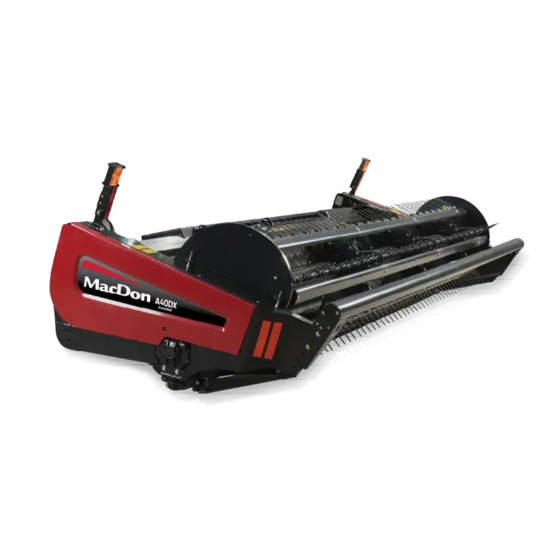
- Page 1 D2 Series Draper Header with FM200 Float Module Operator’s Manual MAC215990 Revision A Original Instruction...
- Page 2 © 2023 MacDon Industries, Ltd. The information in this publication is based on the information available and in effect at the time of printing. MacDon Industries, Ltd. makes no representation or warranty of any kind, whether expressed or implied, with respect to the...
- Page 3 Declaration of Conformity MAC215990 Revision A...
- Page 4 MAC215990 Revision A...
- Page 5 MAC215990 Revision A...
- Page 6 MAC215990 Revision A...
- Page 7 MAC215990 Revision A...
- Page 8 MAC215990 Revision A...
- Page 9 MacDon provides warranty for Customers who operate and maintain their equipment as described in this manual. A copy of the MacDon Industries Limited Warranty Policy, which explains this warranty, should have been provided to you by your Dealer. Damage resulting from any of the following conditions will void the warranty: •...
- Page 10 Keep your MacDon publications up-to-date. The most current English version can be downloaded from our website (www.macdon.com) or from our Dealer-only site (https://portal.macdon.com) (login required). Call your MacDon Dealer if you need assistance, information, or additional copies of this manual. Figure 1: Manual Storage Location viii...
- Page 11 Recording Model and Serial Number Record the model number, serial number, and model year of the header, float module, and transport/stabilizer wheel option (if installed) in the spaces provided. D2 Series Draper Header Header Model: Serial Number: Model Year: The header’s serial number plate (A) is located on the back of the header, beside the left endsheet.
-
Page 13: Table Of Contents
TABLE OF CONTENTS Introduction ............................. vii Recording Model and Serial Number......................ix Chapter 1: Safety ............................1 1.1 Safety Alert Symbols ..........................1 1.2 Signal Words ............................2 1.3 General Safety ............................3 1.4 Maintenance Safety ..........................5 1.5 Hydraulic Safety .............................7 1.6 Tire Safety.............................8 1.7 Decommissioning and Disposing of Agricultural Equipment................9 1.8 Safety Signs ............................ - Page 14 TABLE OF CONTENTS 3.6.1 New Holland Combines ......................... 55 Attaching Header to New Holland CR or CX Combine ................ 55 Detaching Header from New Holland CR or CX Combine..............60 Feeder Deflectors – New Holland CR Series Combines............... 65 3.7 Header Setup............................66 3.7.1 Header Attachments........................
- Page 15 TABLE OF CONTENTS 3.9.11 Reel Fore-Aft Position ....................... 144 Adjusting Reel Fore-Aft Position ....................145 Repositioning Fore-Aft Cylinders....................145 Checking and Adjusting Fore-Aft Position Sensor ................150 3.9.12 Reel Tine Pitch ......................... 152 Reel Cam Settings ........................152 Adjusting Reel Cam ........................154 3.9.13 Upper Cross Auger ........................
- Page 16 TABLE OF CONTENTS 3.14.1 Transporting Header on Combine....................221 3.14.2 Towing ........................... 221 Attaching Header to Towing Vehicle .................... 222 Precautions for Towing Header ....................222 3.14.3 Converting from Transport to Field Position (Option)..............223 Removing Tow-Bar........................223 Storing Tow-Bar........................226 Moving Front (Left) Wheels into Field Position................
- Page 17 TABLE OF CONTENTS 4.5.1 Replacing Light Bulbs ........................271 4.6 Header Drive ............................. 272 4.6.1 Removing Driveline ........................272 4.6.2 Installing Driveline........................274 4.6.3 Removing Driveline Guard ......................277 4.6.4 Installing Driveline Guard ......................279 4.6.5 Adjusting Chain Tension – Main Gearbox ..................281 4.6.6 Adjusting Chain Tension –...
- Page 18 TABLE OF CONTENTS Checking Center Hold-Down – Short Knife Guards ................338 Adjusting Center Hold-Down – Short Knife Guards................338 4.9 Knife Drive System..........................340 4.9.1 Knife Drive Box .......................... 340 Checking Oil Level in Knife Drive Box ................... 340 Checking Mounting Bolts ......................
- Page 19 TABLE OF CONTENTS 4.13.4 Reel Fingers..........................396 Removing Steel Fingers......................396 Installing Steel Fingers ....................... 397 Removing Plastic Fingers......................398 Installing Plastic Fingers ......................399 4.13.5 Tine Tube Bushings........................400 Removing Bushings from Reels....................400 Installing Bushings onto Reels ..................... 405 4.13.6 Reel Endshields ........................
- Page 20 TABLE OF CONTENTS 5.1.8 Sunflower Attachment ........................ 451 ™ 5.1.9 VertiBlade Vertical Knife Kit ....................... 452 5.2 Cutterbar Kits ............................ 453 5.2.1 Rock Retarder Kit ........................453 5.2.2 Four-Point Knife Guard ....................... 453 5.3 FM200 Float Module Kits ........................454 5.3.1 10 V Sensor Adapter Kit ......................
-
Page 21: Chapter 1: Safety
Chapter 1: Safety Understanding and consistently following these safety procedures will help to ensure the safety of those operating the machine and of bystanders. Safety Alert Symbols The safety alert symbol indicates important safety messages in this manual and on safety signs on the machine. This symbol means: •... -
Page 22: Signal Words
SAFETY Signal Words Three signal words, DANGER, WARNING, and CAUTION, are used to alert you to hazardous situations. Two signal words, IMPORTANT and NOTE, identify non-safety related information. Signal words are selected using the following guidelines: DANGER Indicates an imminently hazardous situation that, if it is not prevented, will result in death or serious injury. WARNING Indicates a potentially hazardous situation that, if it is not prevented, could result in death or serious injury. -
Page 23: General Safety
SAFETY General Safety Operating, servicing, and assembling machinery presents several safety risks. These risks can be reduced or eliminated by following the relevant safety procedures and wearing the appropriate personal protective equipment. CAUTION The following general farm safety precautions should be part of your operating procedure for all types of machinery. - Page 24 SAFETY • Wear close-fitting clothing and cover long hair. NEVER wear dangling items such as hoodies, scarves, or bracelets. • Keep all shields in place. NEVER alter or remove safety equipment. Ensure that the driveline guards can rotate independently of their shaft, and that they can telescope freely.
-
Page 25: Maintenance Safety
SAFETY Maintenance Safety Maintaining your equipment safely requires that you follow the relevant safety procedures and wear the appropriate personal protective equipment for the task. To ensure your safety while maintaining the machine: • Review the operator’s manual and all safety items before operating or performing maintenance on the machine. - Page 26 SAFETY • Wear protective gear when working on the machine. • Wear heavy gloves when working on knife components. Figure 1.10: Personal Protective Equipment MAC215990 Revision A...
-
Page 27: Hydraulic Safety
SAFETY Hydraulic Safety Because hydraulic fluid is under extreme pressure, hydraulic fluid leaks can be very dangerous. The proper safety procedures must be followed when inspecting for hydraulic fluid leaks and servicing hydraulic equipment. • Always place all hydraulic controls in Neutral before leaving the operator’s seat. -
Page 28: Tire Safety
SAFETY Tire Safety Inflating, installing, removing, and handling tires presents several safety risks that must be taken into account. WARNING • A tire can explode during inflation, causing serious injury or death. • Follow the proper procedures when mounting a tire. Failure to do so can produce an explosion, causing serious injury or death. -
Page 29: Decommissioning And Disposing Of Agricultural Equipment
SAFETY Decommissioning and Disposing of Agricultural Equipment When agricultural equipment is no longer serviceable and needs to be decommissioned and disposed of, recyclable materials including ferrous and non-ferrous metals, rubber, and plastics; fluids such as lubricants, refrigerants, and fuels; and hazardous materials found in batteries, some light bulbs, and electronic equipment must be handled safely and not introduced into the environment. - Page 30 SAFETY • Use appropriate personal protective equipment when removing and handling objects and materials. • Use appropriate personal protective equipment when handling objects with residue from pesticides, fertilizers, or other agricultural chemicals. Follow local regulations when handling and disposing of these objects. •...
-
Page 31: Safety Signs
SAFETY Safety Signs Safety signs are decals placed on the machine where there is a risk of personal injury, or where the Operator should take extra precautions before operating the controls. They are usually yellow. • Keep safety signs clean and legible at all times. •... -
Page 32: Safety Decal Locations
SAFETY Safety Decal Locations Safety signs are usually yellow decals, and are placed on the machine where there is a risk of personal injury, or where the operator has to take extra precaution before operating controls. Figure 1.19: Reel Arms and Endsheets A -MAC360541 –... - Page 33 SAFETY Figure 1.20: Backtube A - MAC313725 – Read Manual / High Pressure Fluid / Header Hazard B - MAC174436 – High Pressure Fluid Hazard C - MAC311493 – Center Prop Lock D - MAC313733 – Header Crushing Hazard MAC215990 Revision A...
- Page 34 SAFETY Figure 1.21: FM200 Float Module A - MAC313728 – Read Manual / Fluid Spray Hazard B - MAC360655 – Released Spring Energy Hazard Figure 1.22: Upper Cross Auger A - MAC279085 – Auger Warning MAC215990 Revision A...
- Page 35 SAFETY Transport System – Tow-Bar (Short Bar Shown; Long Bar Similar) ™ Figure 1.23: EasyMove A - MAC327588 – Hitch Damage Hazard Figure 1.24: Vertical Knife A - MAC313881 – Knife Hazard MAC215990 Revision A...
- Page 36 SAFETY Figure 1.25: Stabilizer Wheels A - MAC327086 – Released Spring Energy Hazard MAC215990 Revision A...
-
Page 37: 1.10 Understanding Safety Signs
SAFETY 1.10 Understanding Safety Signs Safety sign decals use illustrations to convey important safety or equipment maintenance information. MAC174436 High-pressure oil hazard WARNING High-pressure hydraulic fluid can penetrate human skin, which can cause serious injury such as gangrene, which can be fatal. To prevent this: •... - Page 38 SAFETY MAC311493 Reel crushing hazard DANGER • To prevent injury from the fall of a raised reel, fully raise the reel. Stop the engine and remove the key, and engage the mechanical safety lock on each reel support arm before working on or under the reel.
- Page 39 SAFETY MAC313725 Read manual / high pressure fluid / header crushing hazard DANGER To prevent injury or death from improper or unsafe machine operation: • Read the operator’s manual and follow all safety instructions. If you do not have a manual, obtain one from your Dealer.
- Page 40 SAFETY MAC313728 General hazard pertaining to machine operation and servicing / Hot fluid spray hazard DANGER To prevent injury or death from improper or unsafe machine operation: • Read the operator’s manual and follow all safety instructions. If you do not have a manual, obtain one from your Dealer.
- Page 41 SAFETY MAC313733 Header crushing hazard DANGER To prevent injury or death from the fall of a raised header: • Fully raise the header, stop the engine, remove the key, and engage the mechanical safety locks on the combine before going under the header. •...
- Page 42 SAFETY MAC313881 General hazard pertaining to machine operation and servicing / knife hazard DANGER To prevent injury or death from improper or unsafe machine operation: • Read the operator’s manual and follow all safety instructions. If you do not have a manual, obtain one from your Dealer.
- Page 43 SAFETY MAC327086 Released spring energy hazard WARNING To prevent injury: • When servicing or replacing wheel axle components, the lift- assist spring no longer has counterweight and becomes energized. • Do NOT attempt to pry adjustment handle out of a position slot before releasing tension from the assist springs.
- Page 44 SAFETY MAC360541 Reel entanglement / reel crushing hazard DANGER • To prevent injury from entanglement with the rotating reel, stand clear of the header while the machine is running. • To prevent injury from the fall of the raised reel, fully raise the reel, stop the engine, remove the key, and engage the mechanical safety lock on each reel support arm before working on or under the reel.
-
Page 45: Chapter 2: Product Overview
Combined gross vehicle weight CGVW MacDon D225, D230, D235, D241, and D245 rigid draper headers for combines D2 Series Header Export header The header configuration typical outside North America... - Page 46 PRODUCT OVERVIEW Definitions (continued) Term Definition O-ring face seal: A style of fitting commonly used for connecting hoses and tubes. This ORFS style of fitting is also commonly called ORS, which stands for O-Ring Seal Power take-off Society of Automotive Engineers A headed and externally threaded fastener that threads into preformed threads or forms Screw its own thread when inserted into a mating part...
-
Page 47: D2 Series Draper Header Specifications
PRODUCT OVERVIEW D2 Series Draper Header Specifications The following symbols and letters are used in specification tables. D2 | FM200 | Attachments : optional (dealer installed) / –: not available S: standard / O : optional (factory installed) / O Header Specifications Cutterbar Effective cutting width (distance between crop divider points) - Page 48 PRODUCT OVERVIEW Header Specifications (continued) ™ Over-serrated, fine, ClearCut , quick change, bolted, 14 serrations per inch Knife overlap at center (double-knife headers) 3 mm (1/8 in.) Knife Guards Hold-Downs ™ ClearCut pointed - forged and double heat treated (DHT) Forged with single adjustment bolt ™...
- Page 49 PRODUCT OVERVIEW Header Attachments FM200 Float Module Feed draper Width (78 11/16 in.) 107–122 m/min Feed draper Speed (350–400 fpm) 1630 mm Feed auger Width (64 1/8 in.) Feed auger 559 mm (22 in.) Outside diameter Feed auger 356 mm (14 in.) Tube diameter 191–195 rpm Feed auger...
-
Page 50: D2 Series Draper Header Dimensions
PRODUCT OVERVIEW D2 Series Draper Header Dimensions Know the dimensions of your machinery before operating, transporting, or shipping. Figure 2.1: Header Dimensions Header Dimension Frame and Structure Feature Reference Dimension Dimension (A) shows the gearbox rotated Header width in transport position with (storage) with the crop dividers removed 2591 mm (102 in.) FM200 installed (shortest center-link) -
Page 51: D2 Series Draper Header
PRODUCT OVERVIEW D2 Series Draper Header Familiarize yourself with the main components of the header to make it easier to follow the operation and maintenance instructions provided. Figure 2.2: D2 Series Draper Header – Double Reel Shown A - Pick-Up Reel B - Reel Cam C - Divider Cone (Divider Rod Not Shown) D - Endshield... -
Page 52: Fm200 Float Module Component Identification
PRODUCT OVERVIEW FM200 Float Module Component Identification Familiarizing yourself with the main components of the float module will make it easier to follow the operation and maintenance instructions provided in this manual. Figure 2.3: Header Side of FM200 Float Module A - Feed Auger B - Header Float Springs (x4) C - Center-Link... - Page 53 PRODUCT OVERVIEW Figure 2.4: Combine Side of FM200 Float Module A - Main Gearbox B - Completion Gearbox C - Reservoir Oil Level Sight Glass D - Center-Link E - Header Height Control Indicator (x2) F - Bubble Level G - Drain Plug (x2) H - Float Lock Handle (x2) J - Auto Header Height Control (AHHC) Sensor (x2) K - Hydraulic Filter...
-
Page 55: Chapter 3: Operation
• It is your responsibility to read and understand this manual completely before operating the header. Contact your MacDon Dealer if an instruction is not clear to you. • Follow all safety messages in the manual and on safety decals on the machine. -
Page 56: Operational Safety
OPERATION Operational Safety Follow all the safety and operational instructions given in this manual. CAUTION Adhere to the following safety precautions: • Follow all safety and operational instructions provided in your operator’s manuals. If you do not have a combine manual, get one from your Dealer and read it thoroughly. -
Page 57: Reel Safety Props
OPERATION 3.2.2 Reel Safety Props The reel safety props are located on the reel arms. When engaged, the reel safety props prevent the reel from falling unexpectedly. IMPORTANT: To prevent damage to the reel support arms, do NOT transport the header with the reel safety props engaged. Engaging Reel Safety Props Engage the reel safety props anytime you need to work around a raised reel. -
Page 58: Disengaging Reel Safety Props
OPERATION Center reel arm – double-reel headers 5. Rotate handle (A) to release the spring tension and allow the spring to guide the pin into the locked position. 6. Lower the reel until the safety props contact the outer arm cylinder mounts and the center arm pins. -
Page 59: Header Endshields
OPERATION Center reel arm – double-reel headers 4. Move handle (A) outboard and into slot (B) to put the pin into the unlocked position. Figure 3.7: Reel Safety Prop – Center Arm 3.2.3 Header Endshields A hinged, polyethylene endshield is fitted on each end of the header to protect critical drive components. Opening Header Endshields The header endshields covers knife drive components, hydraulic hoses, electrical connections, the header wrench, the spare knife, and the optional transport hitch. -
Page 60: Closing Header Endshields
OPERATION 2. Pull header endshield (A) open. NOTE: The header endshield is retained by tab (B) and will open in direction (C). Figure 3.9: Left Header Endshield 3. If additional clearance is required, pull the header endshield free of tab (A) and then swing the shield toward the rear of the header. -
Page 61: Checking And Adjusting Header Endshields
OPERATION 3. While closing the endshield, ensure header endshield (A) does not contact the top of endsheet (B). If adjustment is required, refer to Checking and Adjusting Header Endshields, page IMPORTANT: The aluminum endsheet will be damaged if the weight of the plastic endshield rests on it. - Page 62 OPERATION 1. Measure clearance (A) between header endshield (B) and endsheet (C). The clearance should be 1–3 mm (0.04–0.12 in.). Figure 3.15: Clearance between Header Endshield and Endsheet 2. If the clearance between the header endshield and the endshield is insufficient, adjust support bracket (A) as follows: Loosen bolts (B).
- Page 63 OPERATION Figure 3.17: Clearance Specifications at the Front of the Endshield 3. Measure clearance (A) between the front of the header endshield and cylindrical weldment (B). The clearance should be 8–18 mm (0.3–0.7 in). 4. Measure clearance (C) between the front of the header endshield and support bracket (D). The clearance should be 6–10 mm (0.24–0.39 in).
- Page 64 OPERATION 5. If the clearances at the front of the endshield are insufficient, adjust the position of hinge arm (A) as follows: Loosen four nuts (B). b. Slide brackets (C) and hinge arm (A) fore or aft as required to achieve the correct clearance. Retighten the hardware.
- Page 65 OPERATION Figure 3.20: Two-Stage Latch 8. When the endshield is closed, two-stage latch (A) must engage first catch (C). This will allow second catch (D) to prevent the endshield from opening completely in case the endshield unlatches by accident. Confirm the endshield latches properly by following Step 9, page 45 to Step...
-
Page 66: Removing Header Endshields
OPERATION Removing Header Endshields Remove the endshields when servicing the end shields. 1. Fully open the header endshield. For instructions, refer to Opening Header Endshields, page 2. Engage latch (A) to prevent any endshield movement. 3. Remove self-tapping screw (B). 4. - Page 67 OPERATION 1. Start the engine. 2. Adjust the reel fully forward. 3. Lower the header fully. 4. Shut down the engine, and remove the key from the ignition. Single-reel drive: 5. Support reel drive cover (A), and rotate spring latch (B) up and over the back plate.
-
Page 68: Installing Reel Drive Cover
OPERATION 8. Unclip upper cover (A) from the lower cover at locations (B), and remove the upper cover. Keep the two clips engaged on the lower cover. Figure 3.25: Upper Drive Cover 9. If necessary, remove lower cover (B) by removing three bolts (A). - Page 69 OPERATION Single-reel drive: 2. Align the slot in the bottom of reel drive cover (A) to tabs (C) on the reel drive back plate support, and slide the reel drive up. Figure 3.27: Drive Cover 3. Rotate spring latch (A) down to secure the upper cover to the reel drive.
-
Page 70: Daily Start-Up Check
OPERATION 5. Position upper cover (A) on the reel drive. Secure the cover with two clips (B) on the lower cover. Figure 3.30: Upper Drive Cover 6. Rotate spring latch (A) down to secure the upper cover to the reel drive. Ensure V-shaped loop (C) points down, and the spring end remains inserted into back plate hole (B) on both sides of the reel drive. - Page 71 OPERATION 1. Inspect the machine for leaks and for any parts that are missing, damaged, or nonfunctional. IMPORTANT: Use the proper procedure when searching for pressurized fluid leaks. For instructions, refer to 4.2.5 Checking Hydraulic Hoses and Lines, page 247. 2.
-
Page 72: Break-In Period
OPERATION Break-in Period During the first 50 hours of operation, certain systems on the header will require extra attention. Follow this procedure to ensure the service life of the header. NOTE: Until you become familiar with the sound and feel of your new header, be extra attentive. DANGER Before investigating an unusual sound or attempting to correct a problem, shut off the engine and remove the key from the ignition. -
Page 73: Shutting Down The Combine
OPERATION Shutting down the Combine Before leaving the operator's seat for any reason, shut down the combine. DANGER To prevent injury or death from the unexpected start-up of the machine, always stop the engine and remove the key from the ignition before leaving the operator’s seat for any reason. To shut down the combine, do the following: 1. -
Page 74: Cab Controls
OPERATION Cab Controls The header is controlled from the combine cab. WARNING Be sure all bystanders are clear of the machine before starting the engine or engaging any header drives. For instructions, refer to your combine operator’s manual for identification of the following in-cab controls: •... -
Page 75: Header Attachment/Detachment
OPERATION Header Attachment/Detachment This chapter includes instructions for configuring, attaching, and detaching the header. Combine Refer to 3.6.1 New Holland Combines, page 55 New Holland CR and CX Series NOTE: Ensure the applicable functions (automatic header height control [AHHC], draper header option, hydraulic center-link option, hydraulic reel drive) are enabled on the combine and the combine computer. - Page 76 OPERATION IMPORTANT: If the combine is NOT equipped with a rock trap, feeder house faceplate (A) MUST be in mid-position (B). For instructions on adjusting the faceplate, refer to the combine operator’s manual. NOTE: A rock trap prevents rocks or debris from entering the combine, and is located on the front of the combine and behind the feeder house.
- Page 77 OPERATION DANGER Ensure that all bystanders have cleared the area. 3. Start the engine. 4. Slowly drive the combine up to the float module until feeder house saddle (A) is directly under float module top cross member (B). 5. Raise the feeder house slightly to lift the header. Ensure that the feeder saddle is fully engaged in the float module frame.
- Page 78 OPERATION FB E Figure 3.37: Multicoupler and Electrical Connections 10. Remove the caps from connectors C81B (A) and (B). 11. Remove the cover from hydraulic receptacle (C). Clean the receptacle mating surfaces. 12. Push in lock button (D) and pull handle (E) to the fully open position. 13.
- Page 79 OPERATION 18. Pull driveline collar (A) back to release the driveline from the support bracket. Remove the driveline from the support bracket. Figure 3.38: Driveline in Storage Position – Driveline B7038 or B7039 Figure 3.39: Driveline in Storage Position – Sidehill/ Hillside Driveline B7180, B7181, or B7326 19.
-
Page 80: Detaching Header From New Holland Cr Or Cx Combine
OPERATION 20. Disengage the float locks by pulling each float lock handle (A) away from the float module and setting it in unlocked position (B). NOTE: The illustration shows the right float lock; the left float lock is similar. Figure 3.41: Float Lock Handle Detaching Header from New Holland CR or CX Combine The header will need to be physically disconnected from the combine, and the hydraulic and electrical connections removed. - Page 81 OPERATION 3. Engage the float locks by pulling each float lock handle (A) away from the float module and setting it in locked position (B). NOTE: The illustration at the right shows the right side of the header. The float lock on the left side of the header is opposite.
- Page 82 OPERATION 5. Store the driveline on driveline support bracket (B) by pulling back collar (A) on the driveline and fitting it onto support bracket (B). Release the collar so it locks into place on the bracket. Figure 3.44: Driveline in Storage Position – Driveline B7038 or B7039 Figure 3.45: Driveline in Storage Position –...
- Page 83 OPERATION 7. Push handle (A) to the closed position until lock button (B) snaps out. Close the cover. Figure 3.47: Float Module Receptacles 8. Position hydraulic quick coupler (A) onto storage plate (B) on the combine. Figure 3.48: Combine Coupler 9.
- Page 84 OPERATION 10. Connect the electrical connector to the combine at location (A). Figure 3.50: Combine Couplers 11. Replace cover (A) on the float module receptacle. Figure 3.51: Float Module Receptacles 12. Lift lever (A) and pull and lower handle (B) to disengage feeder house/float module lock (C).
-
Page 85: Feeder Deflectors - New Holland Cr Series Combines
OPERATION 13. Lower feeder house (A) until the feeder house disengages float module support (B). 14. Back the combine slowly away from the header. Figure 3.53: Header on Combine Feeder Deflectors – New Holland CR Series Combines On New Holland CR Series combines, feeder deflectors may need to be installed. Feeder deflectors are NOT necessary on New Holland CX Series combines. -
Page 86: Header Setup
3.7.1 Header Attachments Optional attachments can improve performance in specific conditions or add features to the header. Optional attachments can be ordered and installed by your MacDon Dealer. Refer to 5 Options and Attachments, page 447 for descriptions of available items. - Page 87 OPERATION MAC215990 Revision A...
- Page 88 OPERATION MAC215990 Revision A...
- Page 89 OPERATION MAC215990 Revision A...
- Page 90 OPERATION MAC215990 Revision A...
- Page 91 OPERATION MAC215990 Revision A...
- Page 92 OPERATION MAC215990 Revision A...
- Page 93 OPERATION MAC215990 Revision A...
- Page 94 OPERATION MAC215990 Revision A...
- Page 95 OPERATION MAC215990 Revision A...
- Page 96 OPERATION MAC215990 Revision A...
- Page 97 OPERATION MAC215990 Revision A...
-
Page 98: Optimizing Header For Straight-Combining Canola
OPERATION 3.7.3 Optimizing Header for Straight-Combining Canola Ripe canola can be straight-combined, but most varieties are susceptible to pod shatter and subsequent seed loss. This section provides information on the recommended attachments, settings, and adjustments to optimize for straight- combining canola to reduce seed loss. Recommended attachments To optimize the header for straight-combining canola, make the following modifications: •... -
Page 99: Reel Settings
OPERATION 3.7.4 Reel Settings Refer to this procedure to learn how various combinations of reel position and cam setting affect the reel finger profile. Effect on Reel Finger Pattern of Cam Setting and Reel Position Number Cam Setting Number Reel Position Reel Finger Pattern (Finger Speed Gain) Number... - Page 100 OPERATION Effect on Reel Finger Pattern of Cam Setting and Reel Position Number (continued) Cam Setting Number Reel Position Reel Finger Pattern (Finger Speed Gain) Number 3 (30%) 6 or 7 4 (35%) 2 or 3 NOTE: • Adjust the reel forward to get closer to the ground while tilting the header back. Fingers/tines will dig into the ground at extreme reel-forward positions, so adjust the skid shoes or header angle to compensate.
-
Page 101: Floating Crop Divider Settings - Optional
OPERATION Floating Crop Divider Settings – Optional 3.7.5 Floating crop dividers can be adjusted for different crop conditions. DANGER To prevent bodily injury or death from the unexpected start-up or fall of a raised machine, always stop the engine, remove the key, and engage the safety props before going under the header for any reason. For instructions on how to make adjustments to the floating crop divider, refer to Adjusting Floating Crop Dividers, page 167. - Page 102 OPERATION Stubble Height 20 mm to 100 mm (3/4 in. to 4 in.) Side Header Header Stubble Fore Aft Top Deflector DownStop Deflector Deflector Main Angle Height Position Whisker Height Height Shoes 100 mm 4 inch Normal 100 mm 4 inch 20 mm 3/4 inch 20 mm...
- Page 103 OPERATION Stubble Height 16 mm to 50 mm (5/8 in. to 2 in.) Cutterbar on Ground Side Header Header Stubble Fore Aft Top Deflector DownStop Deflector Deflector Main Angle Height Position Whisker Height Height Shoes 50 mm 2 inch Normal 50 mm 2 inch 16 mm...
-
Page 104: Float Module Setup
OPERATION Float Module Setup The following sections outline the recommended float module setup guidelines for your specific combine model and crop type; however, the recommendations cannot cover all conditions. If feeding problems develop with the float module, refer to 6 Troubleshooting, page 463. - Page 105 OPERATION Medium Configuration: The medium configuration uses 4 short bolt-on flightings (2 on the left and 2 on the right) and 22 feed auger fingers. NOTE: Dimensions (A) and (B) are the same for both ends of the auger. They should be within 15 mm (9/16 in.) of the numbers given. Medium configuration is a standard configuration for the following combines: •...
-
Page 106: Ultra Narrow Configuration - Auger Flighting
OPERATION Ultra Wide Configuration: The Ultra Wide configuration uses only factory-welded flighting (A) is responsible for conveying the crop. No bolt-on flighting is installed and a total of 30 auger fingers are recommended for this configuration. Ultra Wide configuration is an optional configuration for wide feeder house combines. - Page 107 2 - Wide Configuration 3 - Ultra Narrow Configuration 43. MAC357234 is available only through MacDon Parts. B7345 is available only through MacDon Whole Goods. Both kits contain wear-resistant flightings. 44. The quantity of existing short flightings is either 0, 2, or 4, depending on the current configuration.
- Page 108 OPERATION NOTE: If converting from Ultra Wide Configuration, there is no existing bolt-on flighting to remove because that configuration uses only the factory-welded flighting (A). Figure 3.62: Ultra Wide Configuration MAC215990 Revision A...
- Page 109 OPERATION Figure 3.63: Ultra Narrow Configuration A - Left Long Flighting (MAC287889) B - Right Long Flighting (MAC287890) C - M10 x 20 mm Carriage Bolt (MAC136178) E - Drilled Holes – 11 mm (7/16 in.) 45 F - M10 x 20 mm Button Head Bolt (MAC135723) 46 D - M10 Center Lock Flange Nut (MAC135799) G - M10 x 20 mm Flange Head Bolt (MAC152655) 47 45.
-
Page 110: Narrow Configuration - Auger Flighting
OPERATION Narrow Configuration – Auger Flighting Narrow Configuration uses four long bolt-on flightings (two on the left and two on the right), and 18 auger fingers. Figure 3.64: Narrow Configuration A - Left Long Flighting (MAC287889) B - Right Long Flighting (MAC287890) To convert to Narrow Configuration from Ultra Narrow Configuration: Remove four flightings (A) from the auger and install additional... - Page 111 (A). Figure 3.67: Ultra Wide Configuration 48. MAC357234 is available only through MacDon Parts. B7345 is available only through MacDon Whole Goods. Both kits contain wear-resistant flightings. 49. The quantity of existing short flightings is either 0, 2, or 4, depending on the current configuration.
- Page 112 OPERATION Figure 3.68: Narrow Configuration A - Left Long Flighting (MAC287889) B - Right Long Flighting (MAC287890) C - M10 x 20 mm Carriage Bolt (MAC136178) D - M10 Center Lock Flange Nut (MAC135799) MAC215990 Revision A...
-
Page 113: Medium Configuration - Auger Flighting
107. Figure 3.70: Auger Configurations – Rear View 1 - Wide Configuration 2 - Medium Configuration 50. MAC357233 is available only through MacDon Parts. B7344 is available only through MacDon Whole Goods. Both kits contain wear-resistant flightings. MAC215990 Revision A... - Page 114 OPERATION To convert to Medium Configuration from Narrow or Ultra Narrow Configuration: Two flighting kits (MAC357233 or B7344 ) are required. You will need to replace long flightings (A) with short flightings (B) and install additional auger fingers. A total of 22 auger fingers is recommended for this configuration.
-
Page 115: Wide Configuration - Auger Flighting
OPERATION Figure 3.73: Medium Configuration A - Left Short Flighting (MAC287888) B - Right Short Flighting (MAC287887) C - M10 x 20 mm Carriage Bolt (MAC136178) D - M10 Center Lock Flange Nut (MAC135799) Wide Configuration – Auger Flighting Wide Configuration uses two short bolt-on flightings (one on the left and one on the right), and 30 auger fingers are recommended. - Page 116 OPERATION Figure 3.74: Wide Configuration A - Left Short Flighting (MAC287888) B - Right Short Flighting (MAC287887) To convert to Wide Configuration from Medium Configuration: Remove existing flightings (A) from the auger and install additional auger fingers. A total of 30 auger fingers is recommended for this configuration.
- Page 117 2 - Ultra Narrow Configuration 3 - Wide Configuration 52. MAC357233 is available only through MacDon Parts. B7344 is available only through Whole Goods. Both kits contain wear-resistant flightings. 53. The quantity of existing long flightings is either 4 or 8, depending on the current configuration.
-
Page 118: Ultra Wide Configuration - Auger Flighting
OPERATION Figure 3.78: Wide Configuration A - Left Short Flighting (MAC287888) B - Right Short Flighting (MAC287887) C - M10 x 20 mm Carriage Bolt (MAC136178) D - M10 Center Lock Flange Nut (MAC135799) Ultra Wide Configuration – Auger Flighting Ultra Wide Configuration uses no bolt-on flighting;... - Page 119 OPERATION Figure 3.79: Ultra Wide Configuration A - Factory-Welded Flighting To convert to Ultra Wide Configuration: Remove all existing bolt-on flightings (A) from the auger and install additional auger fingers if required. A total of 30 auger fingers is recommended for this configuration. •...
-
Page 120: Auger Flighting
OPERATION Auger Flighting The auger flighting on the FM200 can be configured for particular harvesting and crop conditions. For instructions, refer to 3.8.1 FM200 Feed Auger Configurations, page 84 for combine/crop specific configurations. Removing Bolt-On Flighting The feed auger has removable flighting that can be customized to the different models of combines. Before removing the bolt-on flighting, determine the quantity and type of flighting required. - Page 121 OPERATION NOTE: The illustration shows new long flighting (A) installed. Figure 3.83: Long Flighting – Right Side 6. Install slot plug (A) with M6 bolt (B) and tee nut (C) at each location from which the flighting was removed. Torque to 9 Nm (80 lbf∙in).
- Page 122 OPERATION 8. Reinstall access cover(s) (A) using retained bolts (B) and the welded nuts inside the auger. Coat bolts with medium- strength threadlocker (Loctite® 243 or equivalent) and torque to 9 Nm (80 lbf∙in). Figure 3.86: Access Cover – Right Side Installing Bolt-On Flighting The feed auger has removable flighting that can be customized to the different models of combines.
- Page 123 OPERATION 5. Line up the new bolt-on flighting (A) in position to determine which slot plugs need to be removed from the auger. The new flighting overlaps on the outboard side of the adjacent flighting. Figure 3.88: Right Side of Auger 6.
- Page 124 OPERATION NOTE: The illustration shows long flighting (A) installed. Figure 3.91: Long Flighting – Right Side 9. Repeat the procedure to install flighting (A) on the left side of the auger. NOTE: Flighting performs best when no gaps are present. If desired, use silicone sealant to fill the gaps.
- Page 125 OPERATION Installing Additional Bolt-On Flighting – Ultra Narrow Configuration Only When converting the feed auger to Ultra Narrow configuration, some hole drilling is required to install additional flighting. NOTE: This procedure assumes the feed auger is currently in Narrow configuration (4 long flightings [A] installed). Figure 3.94: Narrow Configuration To install the four additional long flightings for Ultra Narrow configuration, follow these steps: 1.
- Page 126 OPERATION 8. Drill two 11 mm (7/16 in.) holes at the marked locations (A) on the existing flighting. 9. Reinstall the existing bolt-on flighting. IMPORTANT: Ensure the carriage bolt heads are on the inside of the auger to prevent damage to the internal components. Figure 3.96: Drilling Locations 10.
-
Page 127: Removing Feed Auger Fingers
OPERATION 13. With the flighting in the desired position, mark four hole locations (A) and drill 11 mm (7/16 in.) holes in the auger tube. Figure 3.99: Flighting on Left Side of Auger 14. Remove nearest access cover(s) (B). Retain the cover for reinstallation. - Page 128 OPERATION 1. Start the engine. For instructions, refer to the combine operator’s manual. 2. Raise the reel fully. 3. Shut down the engine, and remove the key from the ignition. 4. Engage the reel safety props. For instructions, refer to Engaging Reel Safety Props, page 5.
-
Page 129: Installing Feed Auger Fingers
OPERATION 8. Position plug (A) into the hole from inside the auger. Secure with two M6 hex head bolts (B) and tee nuts. Torque to 9 Nm (80 lbf∙in). NOTE: Bolts (B) come with a threadlocker patch that will wear off if the bolts are removed. - Page 130 OPERATION 4. Insert guide (B) from inside the auger and secure it with bolts (A) and tee nuts (not shown). IMPORTANT: Always install a new guide when replacing a solid finger. NOTE: Bolts (A) come with a threadlocker patch that will wear off if the bolts are removed.
-
Page 131: Setting Auger Position
OPERATION 3.8.4 Setting Auger Position The auger position has two settings: floating and fixed. The factory setting is the floating position, and is recommended for most crop conditions. Auger float adjustment arms (A) are located at the bottom left and bottom right of the float module. Figure 3.109: Auger Float Adjustment Arms If bolt (A) is next to floating symbol (B), the auger is in the floating position. - Page 132 OPERATION 5. Using a 21 mm wrench, loosen bolt (A) until the bolt head is clear of bracket (B). Figure 3.111: Feed Auger Float Adjustment 6. Using a breaker bar in the square hole on arm (B), move the arm forward until bolt (A) is in the slot on bracket next to the fixed symbol.
-
Page 133: Checking And Adjusting Feed Auger Springs
OPERATION 3.8.5 Checking and Adjusting Feed Auger Springs The feed auger has an adjustable spring tensioning system that allows the auger to float on top of the crop instead of crushing and damaging it. The factory-set tension is adequate for most crop conditions. DANGER To prevent bodily injury or death from the unexpected start-up or fall of a raised machine, always stop the engine, remove the key, and engage the safety props before going under the header for any reason. -
Page 134: Stripper Bars
OPERATION 3.8.6 Stripper Bars A stripper bar kit may have been supplied with your header. Installing the stripper bar kit improves feeding in certain crops, such as rice. For information on removing and installing the stripper bars, refer to 4.11 Stripper Bars, page 368. -
Page 135: Header Operating Variables
OPERATION Header Operating Variables The header will perform better if you adjust it to suit your specific crops and conditions. Correctly adjusting the header reduces crop loss and speeds harvesting. Proper adjustments, along with timely maintenance, will also increase the service life of the header. The variables listed in Table , page 115 and detailed on the following pages will affect the performance of your header. -
Page 136: Adjusting Stabilizer Wheels
OPERATION Adjusting Stabilizer Wheels A properly adjusted header will achieve a balance between the amount of header weight carried by the float and the amount carried by the stabilizer wheels. Refer to 3.7.2 Header Settings, page 66 for recommended use in specific crops and crop conditions. NOTE: When cutting off the ground using stabilizer wheels: If stubble is uneven when cutting off the ground on stabilizer wheels, and other common header leveling problems have been eliminated (refer to... -
Page 137: Adjusting Easymove ™ Transport Wheels
OPERATION ™ Adjusting EasyMove Transport Wheels A properly adjusted header will achieve a balance between the amount of header weight carried by the float and the amount carried by the transport wheels. DANGER To prevent injury or death from the unexpected start-up of the machine, always stop the engine and remove the key from the ignition before leaving the operator’s seat for any reason. -
Page 138: Cutting On Ground
OPERATION 3.9.2 Cutting on Ground Cutting height will vary depending on crop type, crop conditions, cutting conditions, etc. Cutting on the ground is performed with the header fully lowered and the cutterbar on the ground. The orientation of the knife and knife guards relative to the ground (header angle) is controlled by the skid shoes and the center-link—it is NOT controlled by the header lift cylinders. -
Page 139: Adjusting Outer Skid Shoes
OPERATION 5. Remove lynch pin (A) from each skid shoe. 6. Hold shoe (B) and remove pin (C) by disengaging from the frame and pulling away from the shoe. 7. Raise or lower skid shoe (B) to achieve the desired position using the holes in support (D) as a guide. -
Page 140: Header Float
OPERATION 5. Remove lynch pin (A) from each skid shoe pin (C). 6. Hold skid shoe (B) and remove pin (C) by disengaging from the bracket and pulling away from the shoe. 7. Raise or lower skid shoe (B) to achieve the desired position using the holes in the support plate as a guide. -
Page 141: Checking And Adjusting Header Float
OPERATION 1. Set the float for cutting on the ground as follows: Ensure the header float locks are disengaged. For instructions, refer to Locking/Unlocking Header Float, page 131. b. Lower the feeder house using the combine header controls until float indicator (A) reaches the desired float value (cutterbar ground force). - Page 142 OPERATION Preliminary steps 1. Park the combine on a level surface. 2. Locate spirit level (A) on top of the float module frame. Ensure that the bubble is in the center. If adjustment is required, refer to 3.11 Leveling Header, page 217.
- Page 143 OPERATION 9. If the pointer is not on zero, loosen bolt (A) and slide float indicator plate (B) until pointer (C) is on 0 (D). Tighten the nut on bolt (A). Figure 3.125: Float Indicator 10. On the left side of the float module, pull float lock handle (A) away from the float module, and pull the float lock handle down and into position (B) (UNLOCK).
- Page 144 OPERATION 12. Open the left endshield. For instructions, refer to Opening Header Endshields, page 13. Remove hairpin (A) securing multi-tool (B) to the bracket on the left endsheet. 14. Remove multi-tool (B). Replace the hairpin. Figure 3.127: Multi-Tool Location Setting float setting levers 15.
- Page 145 OPERATION Checking float 20. Set the left float by pushing the left end of the header down by approximately 76 mm (3 in.). Allow the header to rise. Repeat this step at least three times. NOTE: Moving the left side of the header up and down ensures that the reading on the left float setting indicator (FSI) will be accurate.
-
Page 146: Changing Float Spring Configuration
OPERATION 28. On both sides of the float module, lock adjustment bolts (A) with spring locks (B). Ensure that bolt heads (A) are engaged in the spring lock cutouts. Tighten bolts (C) to secure the spring locks. Releasing float setting levers 29. - Page 147 OPERATION Header Component Weights (continued) Divider Option Installed 20 kg (44 lb.) (B) Dividers – select up Rice divider rods to one option 185 kg (408 lb.) Vertical knives UCA Option Installed 142 kg (312 lb.) 9.1 m (30 ft.) two-piece auger (C) Upper cross auger (UCA) –...
- Page 148 OPERATION 5. Lock the header float by pulling the float lock handle into position (A) on the left side of the float module. NOTE: The float is unlocked when the handle is in position (B). 6. Repeat the previous step to set the float lock handle on the other side of the float module.
- Page 149 OPERATION 9. Remove cotter pin (C) from pin (A). 10. Remove pin (A) and washers (B). Figure 3.134: Left Float Spring Installed in Rear Float Lever Hole 11. Align the spring with front float lever hole (A) or back float lever hole (B) according to the specifications in Table , page 127.
- Page 150 OPERATION 12. Install pin (A) and two washers (B) into the new hole. 13. Secure the pin with cotter pin (C). 14. Repeat Step 9, page 129 to Step 13, page 130 to configure other spring (D). Figure 3.136: Left Float Spring – Installed in Rear Float Lever Hole 15.
-
Page 151: Locking/Unlocking Header Float
OPERATION Locking/Unlocking Header Float Two header float locks—one on each side of the float module—lock and unlock the header float system. IMPORTANT: The float locks must be engaged when the header is being transported with the float module attached so there is no relative movement between the float module and the header. - Page 152 OPERATION 1. Set the header angle according to the type and condition of crop and soil as follows: Use shallower settings (A) (position A on the indicator) for normal cutting conditions and wet soil to reduce soil buildup at the cutterbar. Shallow angle settings also minimize damage to the knife in stony fields.
-
Page 153: Adjusting Header Angle From Combine
OPERATION Adjusting Header Angle from Combine The header angle is adjusted from the combine cab using a switch on the operator’s control handle and an indicator on the center-link or on the monitor in the cab. The header angle is determined by the length of the center-link between the combine float module and the header, or by the degree of feeder house tilt on certain combine models. -
Page 154: Optional Reel Drive Sprockets
With these two optional sprockets installed, switching from high-torque to high-speed and vice versa will be quick and easy. For sprocket information, refer to Table , and , page 135. Contact your MacDon Dealer for ordering information. Figure 3.144: Reel Drive with Optional Sprockets... -
Page 155: Ground Speed
OPERATION Optional Sprockets Machine Optional Drive Sprocket Application Combine Hydraulics Sprocket Dual reel drive 20.68 MPa New Holland CR, CX Combining down rice 14/20 tooth sprocket (A) (3000 psi) — Lower sprocket (B) Light crops 52 tooth 3.9.6 Ground Speed Operating the header at the appropriate ground speed for the conditions results in cleanly cut crop and even feeding. -
Page 156: Feed Draper Speed
OPERATION 1. Rotate knob (A) to setting 6 as a starting point. NOTE: Switch (B) activates the header tilt or reel fore-aft controls. For instructions on header tilt or reel fore-aft controls, refer Adjusting Header Angle from Combine, page 133. NOTE: For CNH combines the switch to activate the header tilt or reel fore-aft controls is on the back of the ground speed... -
Page 157: Knifehead Shield
OPERATION 3.9.8 Knifehead Shield The knifehead shield attaches to the endsheet and reduces the knifehead opening to prevent cut crop from accumulating in the knifehead cutout. IMPORTANT: Remove the shields when using the cutterbar on the ground in muddy conditions. Mud may pack into the cavity behind the shield which could result in knife drive box failure. -
Page 158: Knife Speed Information
OPERATION 3.9.9 Knife Speed Information The float module is driven by a driveline that is attached to the combine feeder house. The driveline attaches to a gearbox that drives the knife drive pump. Feeder House Speed Feeder House Speed (rpm) Combine Make New Holland D2 Series Header Knife Speed... -
Page 159: Reel Height
(spm) (1 rpm = 2 spm). 7. Shut down the engine, and remove the key from the ignition. 8. Contact your MacDon Dealer if the pulley rpm measurement exceeds the specified rpm range for your header. For more information refer to 3.9.9 Knife Speed... -
Page 160: Checking And Adjusting Reel Height Sensor
OPERATION The following conditions might result if the reel is set too low: • Crop loss over the header backtube • Crop disturbance on the drapers caused by the reel fingers • Crop pushed down by the tine tubes • Tall crop wrapped around the reel drive and ends The following conditions might result if the reel is set too high: •... - Page 161 OPERATION 3. On the right endsheet, locate reel height sensor (A). It connects to the right reel arm. Figure 3.151: Reel Height Sensor Location Figure 3.152: Sensor Arm/Pointer Configurations A - Incorrect Configuration B - Case/New Holland Configuration C - Sensor Arm D - Sensor Pointer (Located Between Sensor and Sensor Arm) 4.
- Page 162 OPERATION Checking and adjusting sensor output voltage when reel is lowered 6. Engage the parking brake. 7. Start the engine. For instructions, refer to the combine operator’s manual. 8. Lower the reel fully. 9. Use the combine display or a voltmeter to measure the voltage range when the reel is lowered. Refer to Table , page for the recommended voltage ranges.
-
Page 163: Replacing Reel Height Sensor
OPERATION 17. Using a voltmeter, measure the voltage between the ground (pin 2 wire) and the signal (pin 3 wire) at reel height sensor (A). 18. If the voltage is not within the recommended range, loosen two M5 hex nuts (B) and rotate sensor (A) to achieve the recommended voltage range. -
Page 164: Reel Fore-Aft Position
OPERATION 6. Remove two nyloc nuts, washers, and bolts (A) securing sensor (B) to the header frame. Remove the sensor. 7. Install new sensor (B) onto bracket (C) on the header frame. Attach it using retained bolts (A), washers, and nyloc nuts. -
Page 165: Adjusting Reel Fore-Aft Position
OPERATION The reel position indicator (A) is located at the left reel arm. Bracket (B) is the reel fore-aft position marker. For straight standing crop, center the reel over the cutterbar (4–5 on indicator). For crops that are down, tangled, or leaning, it may be necessary to move the reel ahead of the cutterbar (lower number on indicator). - Page 166 OPERATION IMPORTANT: Ensure that all fore-aft cylinders are set to the same position. 1. Adjust the reel height so that the reel arms are parallel with the ground. 2. Shut down the engine, and remove the key from the ignition. 3.
- Page 167 OPERATION 5. Refer to Figure 3.161, page 147 to determine the fore-aft cylinder adjustment procedures for your header type. The number on the illustration refers to one of the following procedures: • For reel arms with fore-aft cylinder adjustment [1] at the front, refer to Step 1, page 148 •...
- Page 168 OPERATION To change the reel position on fore-aft cylinders that adjust at the front of the reel arm, follow these steps: 1. Remove split ring (A), clevis pin (B), and flat washer (not shown) securing the adjustable fore-aft cylinder in the forward position.
- Page 169 OPERATION To change the reel position on fore-aft cylinders that adjust at the back of the reel arm, follow these steps: 1. Remove split ring (A) and clevis pin (B) securing the left cylinder in the forward position on cylinder bracket (C). Figure 3.165: Fore-Aft Cylinder Adjustment Type 2 –...
-
Page 170: Checking And Adjusting Fore-Aft Position Sensor
OPERATION 4. Ensure that there is still adequate clearance between the reel and the following parts of the header: • Backsheet • Reel braces • Upper cross auger (if this is installed on the header) 5. If necessary, adjust the reel tine pitch. For instructions, refer to 3.9.12 ., page 152. - Page 171 OPERATION Checking and adjusting sensor output voltage DANGER Ensure that all bystanders have cleared the area. 4. Engage the parking brake. IMPORTANT: To measure the output voltage of the fore-aft sensor, the engine needs to be running and supplying power to the sensor.
-
Page 172: Reel Tine Pitch
OPERATION 9. If adjustment is required, loosen hardware (A) and rotate sensor (B) until the voltage is in the correct range. 10. Once sensor adjustment is complete, torque the hardware to 2.1 Nm (22 lbf·in). Figure 3.171: Fore-Aft Sensor 3.9.12 Reel Tine Pitch Reel tine pitch is a term used to describe the position of the reel fingers in relation to the cutterbar. - Page 173 OPERATION Cam Position 2, Reel Position 3 or 4 is the recommended starting position for most crops and conditions. • If the crop is stalling on the cutterbar when the reel is in the forward position, increase the cam setting to push the crop past the rear edge of the cutterbar.
-
Page 174: Adjusting Reel Cam
OPERATION Cam Position 4, Header Angle at Maximum, and Reel Fully Forward provides the maximum amount of reel reach below the cutterbar to pick up lodged crops. • This position leaves a significant amount of stubble when the cutting height is set to approximately 203 mm (8 in.). In damp materials such as rice, it is possible to double ground speed because of the reduction of cut material. -
Page 175: Upper Cross Auger
OPERATION 3. Turn latch pin (A) COUNTERCLOCKWISE using multi-tool to release the cam disc. IMPORTANT: Refer to the cam latch decal for the locking/unlocking rotation direction. Forcing the cam latch in the wrong direction can damage the roll pins. 4. Use the multi-tool on bolt (B) to rotate the cam disc and align latch pin (A) with the desired cam disc hole position (C) (1 to 4). - Page 176 OPERATION The mount(s) are initially installed in the rear-most position, so that front bolt (A) is in the primary position. This is the recommended configuration for most conditions. When front bolt (A) is in the primary position, the auger and the reel are safe to operate in any position.
- Page 177 OPERATION Move the auger forward to • Help convey light crops, especially on side hills • Improve the feeding of light crops • Reduce the reel carry over or the crop flow disruption caused by the reel Move the auger rearward to •...
-
Page 178: Checking Upper Cross Auger For Interference
OPERATION To adjust the auger position, do the following: 1. Locate the adjustable mount. NOTE: On two-piece augers, the adjustable mount protrudes from the center support assembly. On three-piece augers, the adjustable mount protrudes from the ends of the center auger. NOTE: The illustration shows the left adjustable mount on a three- piece auger. -
Page 179: Crop Dividers
OPERATION DANGER To prevent injury or death from the unexpected startup of the machine, stop the engine and remove the key from the ignition before you make adjustments to the machine. 3. Shut down the engine, and remove the key from the ignition. 4. -
Page 180: Installing Crop Dividers
OPERATION 5. Remove lynch pin (A). 6. Hold onto crop divider (E). 7. Rotate hex shaft (B) on divider latch (C) forward to disengage it from bolt (D). Figure 3.185: Crop Divider with Latch 8. Lower crop divider (A), and remove it from the endsheet. 9. - Page 181 OPERATION 1. Start the engine. 2. Lower the reel fully. 3. Raise the header fully. 4. Shut down the engine, and remove the key from the ignition. 5. Engage the header safety props. For instructions, refer to the combine operator’s manual. 6.
-
Page 182: Removing Floating Crop Dividers
OPERATION 12. Engage latch (A) onto crop divider bolt (B). 13. Rotate hex shaft (D) on latch (A) counter-clockwise to engage lock. NOTE: Hex shaft (D) requires a torque of 40–54 Nm (30–40 lbf·ft) to close the latch. If adjustment is required, loosen latch (A) and adjust bolt (B) to correct the amount of torque required. - Page 183 OPERATION 6. Retrieve multi-tool (A) from the left endsheet. 7. Remove lynch pin (B). 8. Install multi-tool (A) onto hex shaft (C). 9. Rotate the multi-tool downwards until latch (D) releases from bolt (E). 10. Lift latch (D) up and off bolt (E). Figure 3.192: Floating Crop Divider Installed 11.
-
Page 184: Installing Floating Crop Dividers
OPERATION Installing Floating Crop Dividers Follow these instructions to properly install the floating crop dividers onto the header. DANGER To prevent bodily injury or death from the unexpected start-up or fall of a raised machine, always stop the engine and remove the key from the ignition before making adjustments to the machine. - Page 185 OPERATION 9. Insert crop divider lugs (A) into the slots in the header frame. Figure 3.195: Crop Divider Installation 10. Lift the forward end of quick latch (A), and rotate crop divider (B) up into position. Figure 3.196: Quick Latch MAC215990 Revision A...
- Page 186 OPERATION 11. Engage quick latch (A) onto the bolt. 12. Make sure the latch closes tightly and crop divider stop (B) contacts header stop (C). Figure 3.197: Crop Divider Latched to Header 13. If the latch requires adjustment, loosen nut (A), and adjust the length of bolt (B) until it takes 40–54 Nm (30–40 lbf∙ft) of torque on hex shaft (C) to close the latch.
-
Page 187: Adjusting Floating Crop Dividers
OPERATION Adjusting Floating Crop Dividers Crop dividers can be adjusted for different crop conditions. DANGER To prevent bodily injury or death from the unexpected start-up or fall of a raised machine, always stop the engine and remove the key from the ignition before making adjustments to the machine. NEVER climb onto or go underneath an unsupported header. - Page 188 OPERATION MAC215990 Revision A...
- Page 189 OPERATION MAC215990 Revision A...
- Page 190 OPERATION MAC215990 Revision A...
- Page 191 OPERATION MAC215990 Revision A...
- Page 192 OPERATION MAC215990 Revision A...
- Page 193 OPERATION MAC215990 Revision A...
- Page 194 OPERATION 12. Down stop: Remove lynch pin (A) from the clevis pin, and remove the clevis pin. 13. Tilt the divider and install the clevis pin into a numbered hole “1” to “3”. Secure the clevis pin with the lynch pin. Figure 3.199: Down Stop Adjustment 14.
- Page 195 OPERATION 15. Top deflector height: Loosen the nuts on bolts (A), slide the center support to the desired setting (1 to 4.5), and tighten the nuts. • Align the dots with the support to set half-increments. Example (B) is 2.5. •...
- Page 196 OPERATION 17. Top deflector side rod: Loosen nut (A) and bolt (B), and swing rod (C) outward or inward. Tighten nut (A) to 39 Nm (29 lbf·ft). Tighten bolt (B) to 52 Nm (38 lbf·ft). Figure 3.203: Top Deflector Side Rod Adjustment Figure 3.204: Floating Crop Divider Range of Motion 18.
-
Page 197: Crop Divider Rods
OPERATION 3.9.15 Crop Divider Rods Removable crop divider rods are provided with the header and to be used in conjunction with crop dividers to help separate crop when harvesting. The rods are most useful when crop is bushy or down. In standing crops, using only crop dividers is recommended. -
Page 198: Installing Crop Divider Rods
OPERATION Installing Crop Divider Rods The crop divider rods can be installed on the ends of the crop dividers to help separate bushy crop. 1. Open the right endshield. For instructions, refer to Opening Header Endshields, page 2. Undo lynch pin (A) securing divider rods (B) to the header endsheet. -
Page 199: Optional Rice Divider Rods
OPERATION Optional Rice Divider Rods The optional rice divider rods are used assist with tall and tangled rice crops. They can be installed on the ends of the crop dividers. Rice divider rods provide improved performance in tall and tangled rice crops. For more bundle information, refer to 5.1.7 Rice Divider Rod Kit, page 450. -
Page 200: 3.10 Auto Header Height Control System
OPERATION 3.10 Auto Header Height Control System MacDon’s auto header height control (AHHC) system works in conjunction with the AHHC option available on certain combine models. Two Hall effect sensors (A) are installed on the float setting indicators on the float module. These sensors send signals to the combine, which allow the combine to maintain the header at a consistent cutting height and the optimum float setting as the header follows the contours of the ground. -
Page 201: Auto Header Height Control Sensor Operation
OPERATION 3.10.1 Auto Header Height Control Sensor Operation The position sensors supplied with the auto header height control (AHHC) system communicate data about the header’s height to the combine’s computer. Figure 3.212: Height Control Sensor Locations on Float Module Auto header height control sensor overview Two Hall effect sensors are installed on float indicator needles (A). - Page 202 OPERATION Auto header height control sensor voltage ranges The voltage reported by the sensors occurs in a range of at least 2.5 V (Range [A]) and at most 4.0 V (Range [C]). The ideal voltage range for the sensors is 0.7–4.3 V (Range C), a total range of 3.6 V.
-
Page 203: Recommended Sensor Output Voltages For Combines
OPERATION A sensor configured to have a voltage range that is less than 2.5 V (for example, range [C]) will have difficulty staying within the ideal range of 3.6 V. The combine will seek to keep the sensor within the narrow set range, resulting in the combine continually “hunting”... - Page 204 OPERATION 3. Position the header so that the cutterbar is 254–356 mm (10–14 in.) off the ground. Checking sensor upper voltage limit 4. Extend the guard angle until header angle indicator (A) is at E. Figure 3.216: Center-Link 5. Check that the float lock linkage is on the down stops (washer [A] cannot be moved) at both locations.
- Page 205 OPERATION 6. If the pointer is not on zero, loosen bolt (A) and slide float indicator plate (B) until pointer (C) is on 0 (D). Tighten the nut on bolt (A). 7. Shut down the engine, and remove the key from the ignition.
- Page 206 OPERATION 13. If you need to adjust the voltage, then loosen both nuts (A), reposition sensor (B) in the indicator plate, and then tighten nuts (C) to 3 Nm (22 lbf·in.). While tightening the nuts, make sure that sensor (D) does NOT move in the indicator plate.
-
Page 207: Replacing Float Height Sensor
OPERATION 15. Fully lower header the to the ground. Float indicator pointer (A) should be at 4 (B). 16. Turn the key to the run position. 17. On connector P600, compare the voltage reported by the left sensor (pins 1 and 8) and the right sensor (pins 3 and 8) to the lower voltage specified in 3.10.2 Recommended Sensor Output Voltages for Combines, page... -
Page 208: Volt Adapter - New Holland Combines Only
OPERATION 8. Remove two bolts and nuts (A). 9. Remove and discard old sensor (B). 10. Install new sensor (B) so that the plug faces down. 11. Install two bolts and nuts (A) so that the bolt heads are on the same side as the decal. -
Page 209: New Holland Cr And Cx Series Combines - 2014 And Earlier
OPERATION New Holland CR and CX Series Combines – 2014 and Earlier 3.10.6 To make your header’s auto header height control (AHHC) system compatible with New Holland CR/CX Series combines, you must set your combine’s header configuration options for the particular model of header, configure the reel speed settings, set up the AHHC controls, and calibrate the AHHC system to ensure that it is working correctly. - Page 210 OPERATION 4. If the pointer is not on zero, loosen bolt (A) and slide float indicator plate (B) until pointer (C) is on 0 (D). Tighten the nut on bolt (A). Figure 3.228: Float Indicator 5. Ensure the header float is unlocked. 6.
-
Page 211: Header Settings Quick Reference - New Holland Cr Series
OPERATION 9. Select HEADER HEIGHT/TILT (A). The PARAMETER page appears. Figure 3.231: New Holland Combine Display 10. Select LEFT HEADER HEIGHT SEN (A), and then select GRAPH button (B). The voltage reading appears at the top of the page. 11. Raise and lower the header to see the full range of voltage readings. -
Page 212: Setting Up Auto Header Height Control - New Holland Cr And Cx Series
OPERATION Header Settings – New Holland CR Series (continued) Setup Parameter Suggested Setting HHC tilt sensitivity Set for best performance Reel height sensor Setting up Auto Header Height Control – New Holland CR and CX Series Auto header height control (AHHC) is set up using the combine display. NOTE: Changes may have been made to the combine controls or the display since this document was published. -
Page 213: Calibrating Auto Header Height Control - New Holland Cr And Cx Series
OPERATION Calibrating Auto Header Height Control – New Holland CR and CX Series The auto header height control (AHHC) sensor output must be calibrated for each combine, or the AHHC feature will not work properly. DANGER Ensure that all bystanders have cleared the area. NOTE: Changes may have been made to the combine controls or the display since this document was published. -
Page 214: Calibrating Maximum Stubble Height - New Holland Cr And Cx Series
OPERATION 2. Select HEADER (A), and press ENTER. The CALIBRATION dialog box opens. NOTE: You can use the up and down navigation keys to move between the options. Figure 3.235: New Holland Combine Display 3. Follow the calibration steps in the order in which they appear in the dialog box. -
Page 215: Adjusting Header Raise Rate - New Holland Cr And Cx Series
OPERATION DANGER Ensure that all bystanders have cleared the area. 1. Select the MAXIMUM STUBBLE HEIGHT calibration dialog box. As you proceed through the calibration process, the display will automatically update to show the next step. 1003774 Figure 3.237: New Holland Calibration Dialog Box 2. -
Page 216: Setting Header Lower Rate - New Holland Cr And Cx Series
OPERATION 1. Select HEADER RAISE RATE on the combine display. 2. Use the + or – buttons to change the setting. 3. Press ENTER to save the new setting. NOTE: The raise rate can be changed from 32–236 in increments of 34. -
Page 217: Setting Preset Cutting Height - New Holland Cr And Cx Series
OPERATION NOTE: 3.10.7 New Holland Combines – CR Series, 2015 For New Holland CR models 6.80, 6.90, 7.90, 8.90, 9.90, and 10.90, refer to and Later, page 198. DANGER Ensure that all bystanders have cleared the area. 1. Engage the threshing mechanism and the feeder house. 2. -
Page 218: New Holland Combines - Cr Series, 2015 And Later
OPERATION 1. Engage the threshing mechanism and the feeder house with switches (A) and (B). 2. Set HEADER MEMORY rocker switch (D) in STUBBLE HEIGHT/AUTOFLOAT mode position (A) or (B). 3. Raise or lower the header to the desired cutting height using HEADER HEIGHT and HEADER LATERAL FLOAT momentary switch (C). - Page 219 OPERATION NOTE: This section applies only to 2015 and later CR models (6.80, 6.90, 7.90, 8.90, 9.90, and 10.90). For other pre-2015 New 3.10.6 New Holland CR and CX Series Combines – 2014 and Earlier, page Holland combine models, refer to 189.
- Page 220 OPERATION 6. Select DIAGNOSTICS (A) on the main page. The DIAGNOSTICS page appears. Figure 3.247: New Holland Combine Display 7. Select SETTINGS (A). The SETTINGS page appears. Figure 3.248: New Holland Combine Display 8. Select HEADER HEIGHT/TILT (A) from the GROUP drop- down menu.
-
Page 221: Setting Up Auto Header Height Control - New Holland Cr Series
OPERATION 10. Select GRAPH (A). The exact voltage (B) is displayed at the top of the page. 11. Raise and lower the header to see the full range of voltage readings. Figure 3.250: New Holland Combine Display Setting up Auto Header Height Control – New Holland CR Series Auto header height control (AHHC) is set up using the combine display and control handle. - Page 222 DEFAULT to 80/90 at the main menu. This is now a dealer setting. If you need to change the dealer setting, contact your MacDon Dealer. Figure 3.252: New Holland Combine Controls 6. Select HEAD 1 (A). The HEADER SETUP 1 page displays.
- Page 223 OPERATION 9. Select HEAD 2 (A). The HEADER SETUP 2 page displays. Figure 3.255: New Holland Combine Display 10. Select the AUTOFLOAT drop-down menu and set AUTOFLOAT to INSTALLED (A). 11. Select the AUTO HEADER LIFT drop-down menu and set AUTO HEADER LIFT to INSTALLED (B).
-
Page 224: Setting Up Reel Speed - New Holland Cr Series
OPERATION 14. From REEL HEIGHT SENSOR menu (A), select YES. Figure 3.258: New Holland Combine Display Setting up Reel Speed – New Holland CR Series The reel diameter and reel displacement settings will need to be entered into the combine’s computer before the reel can be operated. -
Page 225: Calibrating Auto Header Height Control - New Holland Cr Series
OPERATION 6. Access Dealer mode by simultaneously pressing UNLOAD (A) and RESUME (B) buttons on the control handle for approximately 10 seconds. The DEALER SETTING page should appear and is required to change the REEL DIAMETER and REEL DISPLACEMENT PER REVOLUTION settings. - Page 226 OPERATION NOTE: Changes may have been made to the combine controls or the display since this document was published. Refer to the combine operator’s manual for the most up-to-date information. NOTE: This section applies only to 2015 and later CR models (6.80, 6.90, 7.90, 8.90, 9.90, and 10.90). For other pre-2015 New 3.10.6 New Holland CR and CX Series Combines –...
- Page 227 OPERATION 2. Select CALIBRATION drop-down menu (A). Figure 3.263: New Holland Combine Display 3. Select HEADER (A) from the list of calibration options. Figure 3.264: New Holland Combine Display 4. Follow the calibration steps in the order in which they appear on the page.
-
Page 228: Calibrating Reel Height Sensor And Reel Fore-Aft Sensor - New Holland Cr Series
OPERATION 5. When all steps have been completed, the CALIBRATION COMPLETED message appears on the page. NOTE: If the float was set heavier to complete AHHC calibration procedure, adjust it to the recommended operating float after the calibration is complete. Figure 3.266: New Holland Combine Display Calibrating Reel Height Sensor and Reel Fore-Aft Sensor –... - Page 229 OPERATION 3. Select CALIBRATION drop-down menu (A). Figure 3.268: New Holland Combine Display 4. Select REEL POSITION (A) from the list of calibration options. Figure 3.269: New Holland Combine Display 5. CAUTION statement (A) will appear. Press ENTER. Figure 3.270: New Holland Combine Display MAC215990 Revision A...
-
Page 230: Checking Reel Height Sensor Voltages - New Holland Cr Series
OPERATION 6. If the statement “Confirm varifeed knife is completely retracted”(A) appears, press ENTER. The varifeed knife is not applicable to MacDon headers. Figure 3.271: New Holland Combine Display 7. Follow calibration steps (A) in the order in which they appear on the page. -
Page 231: Setting Preset Cutting Height - New Holland Cr Series
OPERATION 2. Select SETTINGS tab (A). The SETTINGS page opens. 3. From GROUP menu (B), select HEADER. 4. From PARAMETER menu (C), select REEL VERTICAL POSITION. Figure 3.274: New Holland Combine Display 5. Select GRAPH tab (A). The REEL VERTICAL POSITION graph displays. - Page 232 The console has two buttons used for auto height presets. The toggle switch that was present on previous models is now configured as shown at right. MacDon headers only require first two buttons (A) and (B). Third button (C) is not configured.
-
Page 233: Setting Maximum Work Height - New Holland Cr Series
OPERATION 8. Lower the header to the ground. 9. Select RUN SCREENS (A) on the main page. Figure 3.279: New Holland Combine Display 10. Select the RUN tab that shows MANUAL HEIGHT. NOTE: The MANUAL HEIGHT field may appear on any of the RUN tabs. -
Page 234: Configuring Reel Fore-Aft, Header Tilt, And Header Type - New Holland Cr Series
OPERATION 1. Select TOOLBOX (A) on the main page. The TOOLBOX page appears. Figure 3.281: New Holland Combine Display 2. Select FEEDER (A). The FEEDER SETUP page appears. 3. Select MAXIMUM WORK HEIGHT field (B). Figure 3.282: New Holland Combine Display 4. - Page 235 OPERATION NOTE: Changes may have been made to the combine controls or the display since this document was published. Refer to the combine operator’s manual for the most up-to-date information. 1. Shut down the engine. 2. Turn the key to the run position. 3.
- Page 236 There are now two different buttons for the ON GROUND presets. The toggle switch that was present on previous models is now configured as shown at right. MacDon headers only require first two buttons (A) and (B). Third button down (C) is not configured.
-
Page 237: 3.11 Leveling Header
OPERATION 3.11 Leveling Header The float module is set at the factory to provide the proper level for the header and should not normally require adjustment. However, if adjustment is required, a procedure for doing so is provided. Normally, the header level does not need to be adjusted. Before attempting to level the header, perform the following checks: •... - Page 238 OPERATION 6. On the high side of the header, make one small (1/4–1/2 turn) counterclockwise adjustment to nut (A). Do NOT make any further adjustments to the float lock nut on this side of the header yet. IMPORTANT: Adjustment of more than two turns in either direction may adversely affect the header float.
-
Page 239: 3.12 Unplugging Cutterbar
OPERATION 3.12 Unplugging Cutterbar Follow this procedure if an obstruction prevents the cutterbar from working correctly. DANGER To prevent bodily injury or death from the unexpected start-up or fall of a raised machine, always stop the engine and remove the key before leaving the operator’s seat, and always engage the safety props before going under the machine for any reason. -
Page 240: 3.13 Unplugging Float Module Feed Draper
OPERATION 3.13 Unplugging Float Module Feed Draper Crop sometimes gets wedged between the feed draper and the feed deck. Follow this procedure to safely clear any obstructions in the float module’s feed draper. 1. Stop the forward movement of the machine and disengage the header drives. 2. -
Page 241: 3.14 Transport
OPERATION 3.14 Transport There are two ways to transport the header: attached to a combine and towed behind a combine or an agricultural tractor. For more information, refer to • 3.14.1 Transporting Header on Combine, page 221 • 3.14.2 Towing, page 221 3.14.1 Transporting Header on Combine In conditions with good visibility, you can transport the header while it is attached to a combine. -
Page 242: Attaching Header To Towing Vehicle
• Connect the header seven-pole plug wiring harness to the mating receptacle on towing vehicle. (The seven-pole receptacle is available from your MacDon Dealer parts department.) • Ensure that lights are functioning properly and clean the slow moving vehicle sign and other reflectors. Use flashing warning lights unless prohibited by law. -
Page 243: Converting From Transport To Field Position (Option)
OPERATION 3.14.3 Converting from Transport to Field Position (Option) The header needs to be converted back to field position if it was towed to a new location. Removing Tow-Bar Remove the tow bar from the transport location when converting from the transport position. 1. - Page 244 OPERATION Removing tow-bar installed with an extension: 4. Disconnect tow-bar harness (A) from extension harness (B). 5. Remove lynch pin (C) from latch. Figure 3.294: Tow-Bar / Extension Harness 6. Secure tow-bar harness (A) in storage location. 7. Lift up on hitch near latch connection to take weight off of latch.
- Page 245 OPERATION 10. Remove lynch pin (A) from transport pivot (B). 11. Push back on latch (C) to free extension (D). Figure 3.297: Tow-Bar Extension and Transport Pivot 12. Lift extension (A) and pull away from transport pivot (B). 13. Secure extension harness (C) inside the tow-bar extension tube (A).
-
Page 246: Storing Tow-Bar
OPERATION 17. Remove lynch pin (A), then push back on latch (B) to free the tow-bar. Figure 3.300: Tow-Bar and Left Transport Pivot 18. Lift tow-bar (A) and pull away from transport pivot (B). 19. Reinstall lynch pin in left transport pivot for safe keeping. 20. - Page 247 OPERATION 3. Secure tow-bar extension by hooking strap handle (A) onto notch in cradle (B). Figure 3.303: Tow-Bar Extension Storage Tow-bar 4. Open left endshield. For instructions, refer to Opening Header Endshields, page 5. With tow chain and harness (A) facing up, insert hitch end (B) of tow bar into left backtube.
-
Page 248: Moving Front (Left) Wheels Into Field Position
OPERATION Moving Front (Left) Wheels into Field Position This procedure explains how to move the wheels to the highest storage position, but you may want to use a lower position, depending on whether or not you want the wheels to support the header during field operations. This procedure assumes that the tow-bar has been removed. - Page 249 OPERATION 7. Secure latch (B) with lynch pin (A). Figure 3.308: Left Transport Wheels – Rotation Lock Latch Engaged 8. To unlock the pivot, use your foot to apply pressure to bolt (B) while pushing handle (A) downward. Figure 3.309: Left Transport Wheels – Pivot Released 9.
-
Page 250: Moving Rear (Right) Wheels Into Field Position
OPERATION 10. Ensure that pin (A) is visible at the highest storage position in plate (B). Figure 3.311: Left Transport Wheel Pivot Pin in Highest Storage Position Moving Rear (Right) Wheels into Field Position This procedure demonstrates how to move the wheels to the highest storage position, but you may want to use a lower position, depending on whether or not you want the wheels to support the header during field operations. - Page 251 OPERATION 5. On the right transport axle, remove lynch pin (A) from the right transport axle latch. 6. Support the right transport axle using wheel handle (B), then push handle (C) to release the right transport axle from the header frame. 7.
-
Page 252: Converting From Field To Transport Position (Option)
OPERATION 11. Pull transport height adjustment handle (A) and lift axle pivot handle (B) to move the axle to the highest storage position. Ensure that pin (C) is visible at the highest storage position as shown. 12. Adjust the skid shoe position at the right transport leg to match the other skid shoes. -
Page 253: Moving Rear (Right) Wheels Into Transport Position
OPERATION 6. Secure left transport pivot by pushing pivot handle (A) forward until latch is engaged. 7. Pull back on pivot handle to verify that latch is fully engaged. Figure 3.317: Gauge Wheel 8. Remove clevis pin (A) securing latch. 9. - Page 254 OPERATION CAUTION Stand clear of the wheels and release the linkage carefully; the wheels will drop suddenly once the mechanism is released. 1. Fully raise the skid shoe at the right transport axle. For instructions, refer to Adjusting Inner Skid Shoes, page 118.
-
Page 255: Removing Tow-Bar From Storage
OPERATION 6. Use wheel handle and rotate right transport axle (A) under the header frame. Figure 3.323: Right Transport Axle 7. Remove clevis pin (A) from right transport axle latch. 8. Lift right transport axle with wheel handle (B) until latch engages. -
Page 256: Attaching Tow-Bar
OPERATION Tow-Bar 4. Open left endshield. For instructions, refer to Opening Header Endshields, page 5. Pull tow-bar forward until it hits the stop. Lift the tow-bar to free clevis stop (C) and hook (A) from support angle (B), then pull it out of tube. NOTE: Backtube is shown transparent in illustration at right. - Page 257 OPERATION Installing tow-bar and extension: 4. Remove lynch pin (A) from left transport pivot (B). 5. Push extension (D) into lugs of left transport pivot until latch (C) engages. 6. Reinstall lynch pin (A) to transport pivot to secure extension. 7.
- Page 258 OPERATION 13. Connect tow-bar harness (A) to extension harness (B). 14. Reinstall lynch pin (C) to latch to secure tow-bar. Figure 3.331: Tow-Bar / Extension Harness 15. Retrieve tow-bar wiring harness (A) and safety chain (B) from storage location. 16. Connect tow-bar wiring harness to vehicle, and secure safety chain from tow-bar to tow vehicle.
- Page 259 OPERATION 22. Connect extension wiring harness (A) to left transport pivot harness (B). Figure 3.334: Tow-Bar Electrical Connection 23. Retrieve tow-bar wiring harness (A) and safety chain (B) from storage location. 24. Connect tow-bar wiring harness to vehicle, and secure safety chain from tow-bar to tow vehicle.
-
Page 261: Chapter 4: Maintenance And Servicing
Chapter 4: Maintenance and Servicing This chapter contains the information necessary to perform routine maintenance and occasional servicing tasks on your machine. The word “maintenance” refers to scheduled tasks that help your machine operate safely and effectively; “Service” refers to tasks that must be performed when a part needs to be repaired or replaced. For advanced service procedures, contact your Dealer. -
Page 262: Maintenance Requirements
Knifeheads; refer to Every 25 Hours, page 249 50 Hours or Annually Driveline and driveline universals; refer to Every 50 Hours, page 250 72. MacDon recommends keeping a record of daily maintenance as evidence of a properly maintained machine. MAC215990 Revision A... - Page 263 MAINTENANCE AND SERVICING Upper cross auger right bearing; refer to Every 50 Hours, page 250 Upper cross auger sliding hubs; refer to Every 50 Hours, page 250 Upper cross auger center support and U-joint; refer to Every 50 Hours, page 250 Float module auger pivots;...
- Page 264 MAINTENANCE AND SERVICING 100 Hours or Annually (Whichever Occurs First) Auger drive chain; refer to Every 100 Hours, page 254 Float pivots; refer to Every 100 Hours, page Float spring tensioners; refer to Every 100 Hours, page 254 250 Hours or Annually (Whichever Occurs First) Reel shaft bearings;...
-
Page 265: Break-In Inspection
MAINTENANCE AND SERVICING 4.2.2 Break-in Inspection Break-in inspection involves checking belts, fluids, and performing general machine inspections for loose hardware or other areas of concern. Break-in inspections ensure that all components can operate for an extended period without requiring service or replacement. The break-in period is the first 50 hours of operation after the machine’s initial start up. Inspection Item Refer to... -
Page 266: Equipment Servicing - End-Of-Season
MAINTENANCE AND SERVICING Equipment Servicing – End-of-Season 4.2.4 Equipment should be inspected and serviced at the end of each operating season. CAUTION Never use gasoline, naphtha, or any volatile material for cleaning purposes. These materials may be toxic and/or flammable. CAUTION Cover the cutterbar and the knife guards to prevent injury from accidental contact. -
Page 267: Checking Hydraulic Hoses And Lines
MAINTENANCE AND SERVICING 4.2.5 Checking Hydraulic Hoses and Lines Check hydraulic hoses and lines daily for signs of leaks. WARNING • Avoid high-pressure fluids. Escaping fluid can penetrate the skin causing serious injury. Relieve pressure before disconnecting hydraulic lines. Tighten all connections before applying pressure. -
Page 268: Lubrication
MAINTENANCE AND SERVICING Lubrication Grease zerk locations are marked on the machine by decals showing a grease gun and the greasing interval, which will be specified in terms of hours of header operation. Refer to the inside back cover for information on the recommended lubricants. -
Page 269: Every 25 Hours
MAINTENANCE AND SERVICING IMPORTANT: When greasing, clear any debris, and excess grease from around the bearing housing. Inspect the condition of the roller and bearing housing. Grease the feed draper idler roller bearing until grease comes out of the seal. Initial greasing on a new header may require additional grease (may require 5-10 pumps). -
Page 270: Every 50 Hours
MAINTENANCE AND SERVICING Every 50 Hours Maintenance is required to keep your machine operating at peak performance. It also allows you to do a visual inspection of the machine that may help identify issues early. Figure 4.7: Reel A - Reel Drive Chain. To lubricate, refer to 4.3.3 Lubricating Reel Drive Chain, page 260. - Page 271 MAINTENANCE AND SERVICING Use high temperature extreme pressure (EP2) performance grease with 1% max molybdenum disulphide (NLGI Grade 2) lithium base unless otherwise specified. Figure 4.8: Two-Piece Upper Cross Auger A - Upper Cross Auger U-joints (Two Places) B - Upper Cross Auger Sliding Hubs (Two Places) C - Upper Cross Auger Center Bearings (Two Places) D - Right End Bearing IMPORTANT:...
- Page 272 MAINTENANCE AND SERVICING Figure 4.9: Three-Piece Upper Cross Auger A - Upper Cross Auger U-joints (Two Places) B - Upper Cross Auger Sliding Hubs (Two Places) C - Upper Cross Auger Center Bearings (Two Places) D - Right End Bearing IMPORTANT: The Upper Cross Auger must be greased regularly even when turned off as components of the UCA move when the header flexes, regardless of whether the auger is turning or not.
- Page 273 MAINTENANCE AND SERVICING Figure 4.10: FM200 B - Driveline Slip Joint 73 A - Driveline Universal (Two Places) Figure 4.11: FM200 A - Remote Grease Line for Auger Pivot (Right Side) B - Remote Grease Line for Auger Pivot (Left Side) C - Auger Pivot (Left Side) D - Auger Pivot (Right Side) 73.
-
Page 274: Every 100 Hours
MAINTENANCE AND SERVICING Every 100 Hours Maintenance is required to keep your machine operating at peak performance. It also allows you to do a visual inspection of the machine that may help identify issues early. Use high temperature extreme pressure (EP2) performance grease with 1% max molybdenum disulphide (NLGI Grade 2) lithium base unless otherwise specified. - Page 275 MAINTENANCE AND SERVICING Figure 4.13: FM200 A - Main Gearbox Oil Level. To lubricate, refer to 4.3.5 Lubricating Header Drive Main Gearbox, page 262. B - Completion Gearbox Oil Level. To lubricate, refer to 4.3.6 Lubricating Header Drive Completion Gearbox, page 264.
-
Page 276: Every 250 Hours
MAINTENANCE AND SERVICING Every 250 Hours Maintenance is required to keep your machine operating at peak performance. It also allows you to do a visual inspection of the machine that may help identify issues early. Use high temperature extreme pressure (EP2) performance grease with 1% max molybdenum disulphide (NLGI Grade 2) lithium base unless otherwise specified. -
Page 277: Every 500 Hours
MAINTENANCE AND SERVICING Figure 4.16: Reel A - Reel U-joint (One Place) 74 Every 500 Hours Maintenance is required to keep your machine operating at peak performance. It also allows you to do a visual inspection of the machine that may help identify issues early. Use high temperature extreme pressure (EP2) performance grease with 1% max molybdenum disulphide (NLGI Grade 2) lithium base unless otherwise specified. -
Page 278: Greasing Procedure
MAINTENANCE AND SERVICING 4.3.2 Greasing Procedure Greasing points are identified on the machine by decals showing a grease gun and grease interval in hours of operation. Grease point layout decals are located on the header and on the right side of the float module. DANGER To prevent injury or death from the unexpected start-up of the machine, always stop the engine and remove the key from the ignition before leaving the operator’s seat for any reason. - Page 279 MAINTENANCE AND SERVICING 1. Wipe the grease fitting with a clean cloth before greasing to avoid injecting it with dirt and grit. IMPORTANT: Use clean, high-temperature, extreme-pressure grease only. 2. Inject the grease through the fitting with a grease gun until grease overflows the fitting (except where noted).
-
Page 280: Lubricating Reel Drive Chain
MAINTENANCE AND SERVICING Figure 4.22: Decal for Double-Knife Header with Two- Piece Upper Cross Auger Figure 4.23: Decal for Double-Knife Header with Three Piece Upper Cross Auger 4.3.3 Lubricating Reel Drive Chain Lubrication protects the chain and drive sprockets against wear. DANGER To prevent injury or death from the unexpected start-up of the machine, always stop the engine and remove the key from the ignition before leaving the operator’s seat for any reason. -
Page 281: Lubricating Auger Drive Chain
MAINTENANCE AND SERVICING 2. Apply a liberal amount of chain oil with an oil can, brush, or aerosol to the inside of chain (A) while manually rotating reel to cover all of the chain. 3. Reinstall the reel drive cover. For instructions, refer to Installing Reel Drive Cover, page DANGER Ensure that all bystanders have cleared the area. -
Page 282: Lubricating Header Drive Main Gearbox
MAINTENANCE AND SERVICING 2. Apply a liberal amount of grease to chain (A), drive sprocket (B), and idler sprocket (C). 3. Rotate the auger and apply grease to more areas of the chain, if necessary. Figure 4.26: Auger Drive Chain 4. -
Page 283: Adding Oil To Header Drive Main Gearbox
MAINTENANCE AND SERVICING 3. Remove oil level plug (A) from main gearbox (B) and check that the oil level is up to the bottom of the hole. 4. Add oil if required. For instructions, refer to Adding Oil to Header Drive Main Gearbox, page 263. -
Page 284: Lubricating Header Drive Completion Gearbox
MAINTENANCE AND SERVICING 1. Start the engine. For instructions, refer to the combine operator’s manual. 2. Engage the header to warm up the oil. 3. Raise or lower the header to position oil drain plug (A) at its lowest point. 4. -
Page 285: Adding Oil To Header Drive Completion Gearbox
MAINTENANCE AND SERVICING 3. Remove oil level plug (A) from the completion gearbox. The oil should be at the level of the port. 4. If there is an insufficient amount of oil in the completion gearbox, add oil through filler plug (B). For instructions, refer to Adding Oil to Header Drive Completion Gearbox, page... -
Page 286: Changing Oil In Header Drive Completion Gearbox
MAINTENANCE AND SERVICING 3. Remove filler plug (B) and oil level plug (A). 4. Add oil into filler hole (B) until it runs out of oil level plug hole (A). Refer to the inside back cover for recommended fluids and lubricants. 5. - Page 287 MAINTENANCE AND SERVICING 3. Raise or lower the header to position oil drain plug (A) at its lowest point. 4. Shut down the engine, and remove the key from the ignition. 5. Place a suitably sized container (approximately 4 liters [1 US gal]) underneath the gearbox drain to collect the oil.
-
Page 288: Hydraulics
MAINTENANCE AND SERVICING Hydraulics The float module frame acts as an oil reservoir. Refer to the inside back cover for information on the float module’s oil requirements. 4.4.1 Checking Oil Level in Hydraulic Reservoir The oil level in the header’s hydraulic oil reservoir can be inspected via the sight glass on the float module. DANGER To prevent injury or death from the unexpected start-up of the machine, always stop the engine and remove the key from the ignition before leaving the operator’s seat for any reason. -
Page 289: Changing Oil In Hydraulic Reservoir
MAINTENANCE AND SERVICING 2. Clean any dirt or debris from filler cap (A). CAUTION The oil reservoir may be under pressure; remove the cap slowly. 3. Turn filler cap (A) clockwise to remove it. 4. Fill the hydraulic oil reservoir with warm oil (approximately 21°C [70°F]) until the appropriate fill level is reached. -
Page 290: Changing Oil Filter
MAINTENANCE AND SERVICING 4.4.4 Changing Oil Filter The hydraulic oil filter removes solid contaminants that may interfere with the operation of the header’s hydraulic system. The oil filter will need to be changed periodically. Use filter kit (MAC320360) to replace the filter. DANGER To prevent injury or death from the unexpected start-up of the machine, always stop the engine and remove the key from the ignition before leaving the operator’s seat for any reason. -
Page 291: Electrical System
MAINTENANCE AND SERVICING Electrical System The electrical system for the header is powered by the combine. The header has various lights and sensors that require power. 4.5.1 Replacing Light Bulbs Lights are an important safety feature. Replace damaged or malfunctioning bulbs or lamps immediately. DANGER To prevent bodily injury or death from the unexpected start-up of the machine, always stop the engine and remove the key from the ignition before making adjustments to the machine. -
Page 292: Header Drive
MAINTENANCE AND SERVICING Header Drive The header drive consists of a driveline from the combine to the FM200 Float Module gearbox that drives the feed auger and hydraulic pumps. The pumps provide hydraulic power to the drapers, knives, and optional equipment. 4.6.1 Removing Driveline The driveline transfers power from the combine PTO to the header float module completion gearbox. - Page 293 MAINTENANCE AND SERVICING 7. Slide shield (A) along driveline to access quick disconnect collar (B). NOTE: If the cover does not slide, use a prying tool. 8. Pull back quick disconnect collar (B) to release the driveline yoke. Slide the driveline off of the gearbox shaft. 9.
-
Page 294: Installing Driveline
MAINTENANCE AND SERVICING 4.6.2 Installing Driveline The driveline transfers power from the combine PTO to the header’s float module completion gearbox. It will need to be installed on the float module. DANGER To prevent injury or death from the unexpected start-up of the machine, always stop the engine and remove the key from the ignition before leaving the operator’s seat for any reason. - Page 295 MAINTENANCE AND SERVICING 6. On the end of driveline (D) which has arrow (C) pointing toward the collar, pull back quick disconnect collar (A). 7. Slide the yoke onto support bracket (B). 8. Connect safety chain (E) to the support bracket. Figure 4.47: Driveline Shield Figure 4.48: Optional Side-Hill Driveline Shield 9.
- Page 296 MAINTENANCE AND SERVICING 10. Slide the driveline through shield (A). Pull back the quick disconnect collar (B) to release the driveline yoke. 11. Slide the driveline onto the gearbox shaft until it locks onto the shaft. Figure 4.50: Driveline Shield 12.
-
Page 297: Removing Driveline Guard
MAINTENANCE AND SERVICING 4.6.3 Removing Driveline Guard The main driveline guard must remain attached to the driveline during operation, but it can be removed for maintenance purposes. DANGER To prevent injury or death from the unexpected start-up of the machine, always stop the engine and remove the key from the ignition before leaving the operator’s seat for any reason. - Page 298 MAINTENANCE AND SERVICING 4. Use a slotted screwdriver to release grease fitting/lock (A). Figure 4.55: Driveline Guard 5. Rotate driveline guard locking ring (A) counterclockwise using a screwdriver until lugs (B) line up with the slots in the guard. 6. Pull the guard off the driveline. Figure 4.56: Driveline Guard MAC215990 Revision A...
-
Page 299: Installing Driveline Guard
MAINTENANCE AND SERVICING 4.6.4 Installing Driveline Guard The driveline guard must be installed before the header can be safely operated. 1. Slide the guard onto the driveline, and line up the slotted lug on locking ring (A) with arrow (B) on the guard. Figure 4.57: Driveline Guard 2. - Page 300 MAINTENANCE AND SERVICING 4. Push grease fitting (A) back into the guard. Figure 4.60: Driveline Guard 5. Assemble the driveline. IMPORTANT: The splines are keyed to align the universals. Align weld (A) with missing spline (B) when assembling. Failure to align the halves of the shaft can cause excessive vibration and feed auger/gearbox failures.
-
Page 301: Adjusting Chain Tension - Main Gearbox
MAINTENANCE AND SERVICING Adjusting Chain Tension – Main Gearbox 4.6.5 The gearbox drive chain tension is factory-set, but tension adjustments are required after the first 50 hours, then every 500 hours or annually (whichever comes first). With the exception of oil changes, the gearbox drive chain requires no other regular maintenance. -
Page 302: Adjusting Chain Tension - Completion Gearbox
MAINTENANCE AND SERVICING 5. If necessary, turn bolt (B) slightly until retainer plate (A) can be installed. Figure 4.65: Main Gearbox Chain Tensioner 6. Reinstall chain adjusting cover (B) and gasket (C). 7. Install four bolts (A). Torque the hardware to 9.5 Nm (84 lbf∙in). - Page 303 MAINTENANCE AND SERVICING 5. Remove three bolts (A) that secure input driveline guard base (B). Figure 4.67: Completion Gearbox Chain Tensioner Cover 6. Loosen six bolts (B), that secure chain tension hub (A) to the gearbox. 7. Locate machined feature (C). Using a wrench, turn hub (A) clockwise to tighten the chain.
-
Page 304: Auger
MAINTENANCE AND SERVICING Auger The FM200 Float Module auger feeds the cut crop from the draper decks into the combine feeder house. 4.7.1 Adjusting Feed-Auger-to-Pan Clearance There must be adequate clearance between the feed auger and the pan on the float module to ensure smooth crop feeding. - Page 305 MAINTENANCE AND SERVICING 4. Before adjusting the auger-to-pan clearance, check the auger float position to determine how much clearance is required: IMPORTANT: Ensure that bolts (A) are set at the same location on both ends of the header to prevent damage to the machine during operation.
-
Page 306: Checking Feed Auger Chain Tension
MAINTENANCE AND SERVICING 5. Check clearance (C) between the feed auger flighting and the pan. • If the feed auger is in the fixed position, the clearance should be 24–28 mm (15/16–1 1/8 in.). • If the feed auger is in the floating position, the clearance should be 11.5–15.5 mm (7/16–5/8 in.). - Page 307 MAINTENANCE AND SERVICING WARNING To prevent bodily injury from the fall of a raised reel, always engage the reel safety props before going under the raised reel for any reason. WARNING Ensure that all bystanders have cleared the area. NOTE: There are two methods for checking the auger drive chain tension: the quick method is intended for frequent checks;...
-
Page 308: Checking Feed Auger Drive Chain Tension - Thorough Method
MAINTENANCE AND SERVICING 9. Measure the distance between two lines (B). For a new chain: • If distance (B) is 1–4 mm (0.04–0.16 in.), no adjustment is required. • If distance (B) is greater than 4 mm (0.16 in.), the auger drive chain tension needs adjusting. - Page 309 MAINTENANCE AND SERVICING 7. On the left side of the feed auger, remove four bolts (A) and inspection panel (B). 8. Remove bolts (C) and remove indicator/clamp (D) that holds the two covers together. 9. Remove bolt (E). 10. Remove bolt and washer (H) that secure the bottom cover. 11.
-
Page 310: Removing Auger Drive Chain
MAINTENANCE AND SERVICING 13. Position bottom cover (F) and secure with bolt and washer (H). 14. Install bolt (E). 15. Secure the bottom cover to the top cover with clamp/ indicator (D) and bolts (C). 16. Install inspection panel (B) and secure with four bolts (A). Tighten bolts (A) and torque to 3.5 Nm (30 lbf∙in). - Page 311 MAINTENANCE AND SERVICING 3. Place wooden blocks (A) under the auger to prevent the auger from dropping onto the feed draper and damaging it. Figure 4.79: Blocks under the Auger 4. Loosen two bolts (A) and remove bumper (B). Repeat on the opposite side.
- Page 312 MAINTENANCE AND SERVICING 10. To release the chain tension, loosen jam nut (C) and turn thumbscrew (D) counterclockwise to release the bolt holding sprocket (B) and preventing it from being raised up. IMPORTANT: Do NOT loosen thin nut (E) on the inboard side of the idler sprocket spindle.
-
Page 313: Installing Auger Drive Chain
MAINTENANCE AND SERVICING 15. Remove drive sprocket (A) and chain (B) from spline shaft. Figure 4.85: Auger Drive 16. Maneuver auger (A) sideways and forward so that endless chain (B) can be removed from the auger. Figure 4.86: Auger Drive 4.7.4 Installing Auger Drive Chain The auger drive chain transfers power from the main gearbox to the feed auger. - Page 314 MAINTENANCE AND SERVICING 2. Place drive sprocket (B) into chain (A) and align the sprocket onto the shaft. NOTE: The shoulder of drive sprocket (B) should face the auger. Figure 4.88: Auger Drive 3. Apply medium-strength threadlocker (Loctite ® 243 or equivalent) to threads of screw (A).
- Page 315 MAINTENANCE AND SERVICING 6. Rotate the auger in reverse to take up the slack in the lower strand of the chain. IMPORTANT: Do NOT loosen thin nut (C) on the inboard side of the idler sprocket spindle. 7. Turn adjuster thumbscrew (D) clockwise to move idler sprocket (B) until it is FINGER TIGHT ONLY.
-
Page 316: Adjusting Feed Auger Drive Chain Tension
MAINTENANCE AND SERVICING 14. Remove wooden blocks (A) from the feed draper. Figure 4.94: Blocks under the Auger 4.7.5 Adjusting Feed Auger Drive Chain Tension The auger is chain-driven by the float module drive system sprocket attached to the side of the auger. Insufficient chain tension can prematurely wear sprockets or damage the chain. - Page 317 MAINTENANCE AND SERVICING 7. Remove four bolts (A) and inspection panel (B) to view chain. Figure 4.95: Left Side of Auger Drive – Rear View 8. Loosen jam nut (B). 9. Loosen idler nut (A) slightly to allow idler to move by turning adjuster (C).
-
Page 318: Auger Flighting
MAINTENANCE AND SERVICING 12. When adjustment is complete, tighten jam nut (A). 13. Tighten the idler nut (B) and torque to 265 Nm (195 lbf∙ft). 14. Recheck midspan chain deflection after tightening the idler and jam nut. Figure 4.98: Feed Auger Chain – Front View 15. - Page 319 MAINTENANCE AND SERVICING WARNING To prevent bodily injury from the fall of a raised reel, always engage the reel safety props before going under the raised reel for any reason. IMPORTANT: When removing auger fingers, work from the outside inward. Make sure there is an equal number of fingers on both sides of the auger when complete.
- Page 320 MAINTENANCE AND SERVICING 8. Remove and retain two bolts (A) and the tee nuts (not shown) securing finger guide (B) to the auger. Remove guide (B). Figure 4.102: Auger Finger Hole 9. Place plug (A) in the hole from inside the auger. Secure the plug with two M6 hex head bolts (B) and tee nuts.
-
Page 321: Installing Feed Auger Fingers
MAINTENANCE AND SERVICING Installing Feed Auger Fingers The feed auger has fingers that extend and retract to pull crop into the feeder house on the combine. Fingers may need to be installed onto the auger drum to change its configuration profile. DANGER To prevent bodily injury or death from the unexpected start-up of the machine, always stop the engine and remove the key from the ignition before making adjustments to the machine. - Page 322 MAINTENANCE AND SERVICING 5. Remove two bolts (B), tee nuts (not shown), and plug (A). Figure 4.106: Auger Finger Hole 6. Insert guide (B) from inside the auger and secure it with bolts (A) and tee nuts (not shown). IMPORTANT: Always install a new guide when replacing a solid finger.
-
Page 323: Checking Auger Finger Timing
MAINTENANCE AND SERVICING 10. Secure access cover (B) in place with bolts (A). Torque the bolts to 9 Nm (80 lbf∙in). NOTE: Bolts (A) come with a threadlocker patch that will wear off if the bolts are removed. If reinstalling bolts (A), apply medium-strength threadlocker (Loctite®... -
Page 324: Adjusting Auger Finger Timing
MAINTENANCE AND SERVICING Adjusting Auger Finger Timing The feed auger has fingers that extend and retract to pull crop into the feeder house on the combine. This procedure determines where the fingers are when they are fully extended from the auger. NOTE: The illustrations show only the left side of the auger;... - Page 325 MAINTENANCE AND SERVICING NOTE: If the finger timing indicator is pointing at position A, it indicates that at that point the auger fingers will be fully extended. This allows the crop to be engaged and released earlier before entering the feeder house. This setting is best used for canola or bushy crops.
-
Page 326: Knife
MAINTENANCE AND SERVICING Knife The knives on the cutterbar cut the crop. The knives, guards, and knifehead will require maintenance from time to time. WARNING Keep hands clear of the area between guards and knife at all times. WARNING Wear heavy gloves when working around or handling knives. CAUTION To avoid personal injury, before servicing machine or opening drive covers, refer to... -
Page 327: Removing Knife
MAINTENANCE AND SERVICING 4. If a hold-down is present, Loosen nuts (A) that hold hold- down (B) to access the knife section that is being replaced. Figure 4.116: Cutterbar 5. Remove bolts and nuts (B). Retain hardware. NOTE: Stroke the knife as required to access the hardware. 6. -
Page 328: Removing Knifehead Bearing
MAINTENANCE AND SERVICING NOTE: For single knife headers, the knifehead is located on the left side of the knife. For double knife headers, there are two knifeheads and they are located both right and left sides of the knife. Verify which knife needs to be removed before beginning. -
Page 329: Installing Knifehead Bearing
MAINTENANCE AND SERVICING WARNING To prevent bodily injury from the fall of a raised reel, always engage the reel safety props before going under the raised reel for any reason. WARNING Stand to the rear of the knife during removal to reduce the risk of injury from cutting edges. Wear heavy gloves when handling the knife. -
Page 330: Installing Knife
MAINTENANCE AND SERVICING 1. Place O-ring (E) and plug (D) into the knifehead. 2. Use a flat-ended tool (A) with the same approximate diameter as bearing (C), and push the bearing into the knifehead until the top of the bearing is flush with the step in the knifehead. - Page 331 MAINTENANCE AND SERVICING 5. Install knifehead pin (A) through the drive arm and into the knifehead. 6. Position knifehead pin (A) so that groove (B) is 2 mm (5/64 in.) above the drive arm. Figure 4.123: Knifehead 7. Secure the knifehead pin with M16 x 85 mm bolt (A) and nut (B).
-
Page 332: Spare Knives
MAINTENANCE AND SERVICING 11. Move the knife drive arm to the mid-stroke position. Ensure that the knifeback bar doesn’t contact the front of first guard (A). 12. If the knifeback bar contacts the front of the first guard, remove bolts (B), move the guard forward, and reinstall the bolts. - Page 333 MAINTENANCE AND SERVICING Figure 4.128: Guard and Hold-Down Types Used in Pointed Knife Guard Configurations A - Pointed Hold-Down (MAC286329) B - Pointed Knife Guard (MAC286315) C - Pointed-End Knife Guard (without Wear Bar) (MAC286316) 75 ™ D - PlugFree End Hold-Down (MAC286331) End Knife Guard (without Wear Bar) (MAC286319) 76 F - Pointed Center Knife Guard (MAC286317) 77...
-
Page 334: Pointed Knife Guard Configuration On Single-Knife Headers
MAINTENANCE AND SERVICING Pointed Knife Guard Configuration on Single-Knife Headers Knife guards assist with aligning the knife bar. Hold-downs hold the sections on the knife bar down against the knife guards to ensure proper cutting. Figure 4.129: Pointed Knife Guard and Hold-Down Locations – Single-Knife Headers A - Pointed Hold-Down (MAC286329) B - Pointed Knife Guard (MAC286315) C - Pointed End Knife Guard (without Wear Bar) (MAC286316) -
Page 335: Pointed Knife Guard Configuration On Double-Knife Header - D235
MAINTENANCE AND SERVICING Pointed Knife Guard configuration on Double-Knife Header – D235 Knife guards assist with aligning the knife bar. Hold-downs hold the sections on the knife bar down against the knife guards to ensure proper cutting. Figure 4.130: Pointed Guard and Hold-Down Locations A - Pointed Hold-Down (MAC286329) 78 B - Pointed Center Hold-Down (MAC286332) C - Pointed Center Knife Guard (MAC286317) -
Page 336: Pointed Knife Guard Configuration On Double-Knife Header - D241
MAINTENANCE AND SERVICING Pointed Knife Guard Configuration on Double-Knife Header – D241 Knife guards assist with aligning the knife bar. Hold-downs hold the sections on the knife bar down against the knife guards to ensure proper cutting. Figure 4.131: Pointed Knife Guard and Hold-Down Locations A - Pointed Hold-Down (MAC286329) 79 B - Pointed Center Hold-Down (MAC286332) C - Pointed Center Knife Guard (MAC286317) -
Page 337: Pointed Knife Guard Configuration On Double-Knife Header - D245
MAINTENANCE AND SERVICING Pointed Knife Guard Configuration on Double-Knife Header – D245 Knife guards assist with aligning the knife bar. Hold-downs hold the sections on the knife bar down against the knife guards to ensure proper cutting. Figure 4.132: Pointed Guard and Hold-Down Locations A - Pointed Hold-Down (MAC286329) 80 B - Pointed Center Hold-Down (MAC286332) C - Pointed Center Knife Guard (MAC286317) -
Page 338: Adjusting Knife Guards And Guard Bar
Adjusting Knife Guards and Guard Bar If a knife guard or the guard bar is misaligned due to contact with a rock or similar obstruction, use the guard straightening tool (MAC286705) available from your MacDon Dealer to correct the issue. DANGER To prevent bodily injury or death from the unexpected start-up of the machine, always stop the engine and remove the key from the ignition before making adjustments to the machine. - Page 339 MAINTENANCE AND SERVICING 5. To adjust the guard tips downwards, position the tool as shown and push down. Figure 4.135: Downward Adjustment – Pointed Guard Figure 4.136: Downward Adjustment – Short Knife Guard 6. To adjust the guard bar, position the tool as shown, then push down or pull up on the tool accordingly.
-
Page 340: Replacing Pointed Knife Guards
MAINTENANCE AND SERVICING Replacing Pointed Knife Guards Guards become dull and need to be replaced. This procedure is for replacing standard guards and the special (drive side) guards closest to the knife drive motor. DANGER To prevent bodily injury or death from the unexpected start-up of the machine, always stop the engine and remove the key from the ignition before making adjustments to the machine. -
Page 341: Checking Hold-Down - Pointed Knife Guards
MAINTENANCE AND SERVICING 7. Remove two nuts and bolts (B) securing pointed knife guard (A) and hold-down (C) (if applicable) to the cutterbar. 8. Remove pointed knife guard (A), hold-down (C), and the plastic wearplate. Discard the pointed knife guard. Figure 4.139: Pointed Knife Guards 9. -
Page 342: Adjusting Hold-Down - Pointed Knife Guards
MAINTENANCE AND SERVICING NOTE: Align the guards prior to adjusting the hold-down. For instructions, refer to Adjusting Knife Guards and Guard Bar, page 318. DANGER To prevent bodily injury or death from the unexpected start-up of the machine, always stop the engine and remove the key from the ignition before making adjustments to the machine. -
Page 343: Replacing Pointed Center Knife Guard - Double-Knife
MAINTENANCE AND SERVICING WARNING To prevent bodily injury from the fall of a raised reel, always engage the reel safety props before going under the raised reel for any reason. WARNING Wear heavy gloves when working around or handling knives. 1. - Page 344 MAINTENANCE AND SERVICING 1. Raise the reel fully. 2. Shut down the engine, and remove the key from the ignition. 3. Engage the reel safety props. For instructions, refer to Engaging Reel Safety Props, page 4. Remove two nuts and bolts (C) securing guard (A) and hold- down (B) to the cutterbar.
- Page 345 MAINTENANCE AND SERVICING 7. Position plastic wearplate (A) and new guard (B) under the cutterbar. Figure 4.147: Pointed Center Knife Guard and Wearplate 8. Thread three adjustment bolts (A) so they are protruding 4 mm (5/32 in.) from the bottom of pointed center hold- down (B).
-
Page 346: Checking Center Hold-Down - Pointed Knife Guards
MAINTENANCE AND SERVICING Checking Center Hold-Down – Pointed Knife Guards The pointed center knife guard hold-down prevent the center knife section on the cutterbar from lifting off of the guard, while still allowing the knife to slide. The center hold-down will need to be inspected to ensure that there is adequate clearance between the hold-down and the center knife section. -
Page 347: Adjusting Center Hold-Down - Pointed Knife Guards
MAINTENANCE AND SERVICING Adjusting Center Hold-Down – Pointed Knife Guards If the pointed center knife guard hold-down is binding its knife, the center hold-down will need to be adjusted. DANGER To prevent bodily injury or death from the unexpected start-up of the machine, always stop the engine and remove the key from the ignition before making adjustments to the machine. -
Page 348: Short Knife Guards And Hold-Downs
MAINTENANCE AND SERVICING 4.8.8 Short Knife Guards and Hold-Downs Short knife guards are less likely to plug the knife in tough crops such as grasses and canola. The following knife guards and hold-downs are used in short knife guard configurations: Figure 4.152: Guard and Hold-Down Types used in Short Knife Guard Configurations ™... -
Page 349: Short Knife Guard Configuration On Single-Knife Headers
MAINTENANCE AND SERVICING Short Knife Guard Configuration on Single-Knife Headers Figure 4.153: Short Knife Guard and Hold-Down Locations – Single-Knife Headers A - Short Knife Hold-Down (MAC286330) B - Short Knife Guard (MAC286318) C - Short Knife End Hold-Down (x4) (MAC286331) D - Short Knife End Knife Guard (without Wear Bar) (x5) (MAC286319) MAC215990 Revision A... -
Page 350: Short Knife Guard Configuration On Double-Knife Headers - All Sizes Except D241)
MAINTENANCE AND SERVICING Short Knife Guard Configuration on Double-Knife Headers – All Sizes Except D241) Figure 4.154: Short Knife Guard and Hold-Down Locations – Double-Knife Headers A - Short Knife Hold-Down (MAC286330) B - Short Knife Guard (MAC286318) C - Short Knife End Hold-Down (x6) (MAC286331) D -Short Knife End Knife Guard (without Wear Bar) (x8) (MAC286319) E - Short Knife Center Hold-Down (MAC286333) F - Short Knife Center Knife Guard (MAC286320) -
Page 351: Short Knife Guard Configuration On Double-Knife Header - D241
MAINTENANCE AND SERVICING Short Knife Guard configuration on Double-Knife Header – D241 Figure 4.155: Short Knife Guard and Hold-Down Locations – D241 Double-Knife Header A - Short Knife Hold-Down (MAC286330) B - Short Knife Guard (MAC286318) C - Short Knife End Hold-Down (x6) (MAC286331) D - Short Knife End Knife Guard (without Wear Bar) (x8) (MAC286319) E - Short Knife Center Hold-Down (MAC286333) F - Short Knife Center Knife Guard (MAC286320) -
Page 352: Replacing Short Knife Guards Or End Knife Guards
MAINTENANCE AND SERVICING Replacing Short Knife Guards or End Knife Guards Short knife guards or end knife guards are less likely to plug the knife in tough crops such as grasses and canola, and are factory-installed. DANGER To prevent bodily injury or death from the unexpected start-up of the machine, always stop the engine and remove the key from the ignition before making adjustments to the machine. - Page 353 MAINTENANCE AND SERVICING IMPORTANT: The first four knife guards (A) on the drive sides of the header are called end knife guards and do NOT have wear bars. Ensure the proper replacement knife guards are installed at these locations. Figure 4.157: End Knife Guard and Short Knife Guards A - End Knife Guard (MAC286319) B - Short Knife Guard (with wear bar [C]) (MAC286318) 6.
-
Page 354: Checking Hold-Down - Short Knife Guards
MAINTENANCE AND SERVICING Checking Hold-Down – Short Knife Guards The short knife guard hold-downs prevent the knife sections on the cutterbar from lifting off of the guards, while still allowing the knife to slide. The hold-downs will need to be inspected to ensure that there is adequate clearance between the hold-downs and knife sections. -
Page 355: Replacing Center Knife Guard - Double-Knife
MAINTENANCE AND SERVICING WARNING To prevent bodily injury from the fall of a raised reel, always engage the reel safety props before going under the raised reel for any reason. WARNING Wear heavy gloves when working around or handling knives. 1. - Page 356 MAINTENANCE AND SERVICING 1. Raise the reel fully. 2. Shut down the engine, and remove the key from the ignition. 3. Engage the reel safety props. For instructions, refer to Engaging Reel Safety Props, page 4. Remove two nuts and bolts (C) securing center knife guard (A) and hold-down (B) to the cutterbar.
- Page 357 MAINTENANCE AND SERVICING 7. Position plastic wearplate (A) and new center knife guard (B) under the cutterbar. Figure 4.165: Center Knife Guard and Wearplate 8. Thread three adjustment bolts (A) so they are protruding 4 mm (5/32 in.) from the bottom of center hold-down (B). 9.
-
Page 358: Checking Center Hold-Down - Short Knife Guards
MAINTENANCE AND SERVICING Checking Center Hold-Down – Short Knife Guards The short center knife guard hold-down prevent the center knife section on the cutterbar from lifting off of the guard, while still allowing the knife to slide. The center hold-down will need to be inspected to ensure that there is adequate clearance between the hold-down and the center knife section. - Page 359 MAINTENANCE AND SERVICING WARNING Wear heavy gloves when working around or handling knives. 1. Raise the reel fully. 2. Shut down the engine, and remove the key from the ignition. 3. Engage the reel safety props. For instructions, refer to Engaging Reel Safety Props, page 4.
-
Page 360: Knife Drive System
MAINTENANCE AND SERVICING Knife Drive System The knife drive system transforms pumped hydraulic pressure into a mechanical motion that strokes a series of serrated knife blades at the front of the header back and forth to cut a variety of crops. 4.9.1 Knife Drive Box The knife drive box is driven by a hydraulic motor and converts rotational motion into the reciprocating motion of... -
Page 361: Checking Mounting Bolts
MAINTENANCE AND SERVICING 6. Remove oil level dipstick (A). Check the oil level. The oil level must be within range (B), between the lines near the bottom of the dipstick. 7. Reinstall oil level dipstick (A). Tighten the dipstick to 23 Nm (204 lbf·in). - Page 362 MAINTENANCE AND SERVICING 3. Place a container large enough to hold approximately 1.5 L (0.4 US gal) under the knife drive box to collect the oil. 4. Remove dipstick (A) and drain plug (C). 5. Allow the oil to drain from the knife drive box and into the container placed below it.
-
Page 363: 4.10 Feed Deck
MAINTENANCE AND SERVICING 4.10 Feed Deck The feed deck is located on the FM200 Float Module. It consists of a motor and feed draper that conveys cut crop to the feed auger. 4.10.1 Replacing Feed Draper The feed draper on the float module delivers harvested crop into the combine’s feeder house. If the feed draper is torn, cracked, or missing slats, it will need to be replaced. - Page 364 MAINTENANCE AND SERVICING 4. Lower feed deck pan (A). NOTE: Lowering the feed deck pan improves access to the hardware securing the feed draper. 1028369 Figure 4.176: Feed Deck Pan 5. Raise the header fully. 6. Raise the reel fully. 7.
- Page 365 MAINTENANCE AND SERVICING 17. Remove nuts and screws (A). Remove draper connector straps (B). 18. Pull the draper from the deck. Figure 4.179: Draper Connector 19. Install the new draper over drive roller (A). Ensure that the draper guides fit into drive roller grooves (B). 20.
- Page 366 MAINTENANCE AND SERVICING 22. Move the idler roller back to the operating position. 23. Apply medium-strength threadlocker (Loctite ® 243 or equivalent) to the threads of hardware (A). 24. On the side of the feed deck on which the casting dropped when the hardware was removed, reinstall hardware (A) to secure idler roller casting (B) to the frame.
-
Page 367: Checking And Adjusting Feed Draper Tension
MAINTENANCE AND SERVICING 32. Engage lock handle (A) in three feed deck pan hooks (B). Figure 4.185: Underside of Feed Deck Pan 33. Rotate handles (A) upward to bring the feed deck pan into the locked position. NOTE: Ensure that all three deck pan hooks (B) are secured on the lock handle. - Page 368 MAINTENANCE AND SERVICING 5. Check the position of spring retainer disc (A). If the feed draper tracks properly and the spring retainers on both sides of the draper are correctly positioned, then no adjustment is necessary. NOTE: The starting position of spring retainer disc (A) is centered within the U shape on indicator (B);...
-
Page 369: Feed Draper Drive Roller
MAINTENANCE AND SERVICING 4.10.3 Feed Draper Drive Roller The feed draper drive roller is hydraulically driven to rotate the feed draper and convey crop toward the feeder house auger. Removing Feed Draper Drive Roller The feed draper drive roller needs to be removed when repairing or replacing it. DANGER To prevent bodily injury or death from the unexpected start-up or fall of a raised machine, always stop the engine and remove the key before leaving the operator’s seat, and always engage the safety props before going under the... - Page 370 MAINTENANCE AND SERVICING 10. On the right side of the deck, remove two nuts (A) and bolts from drive roller bearing housing (B). Figure 4.191: Drive Roller Bearing 11. Slide the drive roller with bearing assembly (A) to the right until the left end comes off of the motor spline.
-
Page 371: Installing Feed Draper Drive Roller
MAINTENANCE AND SERVICING Installing Feed Draper Drive Roller The feed draper drive roller needs to be installed after it has been repaired or replaced. 1. Apply grease to the motor spline. 2. Guide bearing end (A) of the drive roller through frame opening (B). -
Page 372: Removing Feed Draper Drive Roller Bearing
MAINTENANCE AND SERVICING 4. Install two bolts (A) into the feed deck. 5. Install both covers (B) onto the two bolts. IMPORTANT: Position the covers in the order shown. 6. Secure the drive roller bearing housing using two nuts (C). 7. - Page 373 MAINTENANCE AND SERVICING 6. Locate the feed draper tensioner. Loosen jam nut (A). Turn bolt (B) counterclockwise to relieve the tension on the draper. Figure 4.197: Feed Draper Tensioner 7. Loosen set screw (A) on bearing lock (B). 8. Using a hammer and punch, tap bearing lock (B) in the direction opposite to the auger rotation to release the lock.
-
Page 374: Installing Feed Draper Drive Roller Bearing
MAINTENANCE AND SERVICING 10. Remove bearing housing (A). NOTE: If the bearing is seized on the shaft, it may be easier to remove the drive roller assembly. For instructions, refer to Removing Feed Draper Drive Roller, page 349. 11. Inspect both covers (B) for damage. If they are damaged, replace them with the parts in kit MAC347553. -
Page 375: Feed Draper Idler Roller
MAINTENANCE AND SERVICING 4.10.4 Feed Draper Idler Roller The feed draper idler roller is driven by the friction of the feed draper being turned by the drive roller. Like the drive roller, the idler roller helps the feed draper convey crop to the auger. Removing Feed Draper Idler Roller The feed draper idler roller needs to be removed when being repaired or replaced. - Page 376 MAINTENANCE AND SERVICING 10. Remove dust cap (A) and nut (B) from bearing housing (C). Figure 4.204: Idler Roller Bearing Housing 11. Remove the following hardware from location (A) that secures the bearing housing to the deck skid and tensioner. 12.
-
Page 377: Installing Feed Draper Idler Roller
MAINTENANCE AND SERVICING 15. Slide idler roller (A) out through the cutout in the deck frame. Figure 4.207: Idler Roller Installing Feed Draper Idler Roller The feed draper idler roller needs to be installed after it has been repaired or replaced. 1. - Page 378 MAINTENANCE AND SERVICING 5. Slide idler roller (A) through the cutout in the deck frame. NOTE: The right end of the idler roller should protrude from the right deck frame. Figure 4.210: Feed Deck – Left Side 6. Install the bolt from inside of the feed deck to secure idler cover (A).
- Page 379 MAINTENANCE AND SERVICING 10. After the bearing and both seals are seated around the right shaft, install nut (A) and torque it to 81 Nm (60 lbf·ft). Figure 4.213: Feed Deck – Right Side 11. Rotate idler roller housing (A) until the holes in the lower tabs align with the hole in welded tab (B).
-
Page 380: Replacing Feed Draper Idler Roller Bearing
MAINTENANCE AND SERVICING 19. Close the feed draper and secure it with connector straps (B), screws (A), and nuts. 20. Tension the feed draper. For instructions, refer to 4.10.2 Checking and Adjusting Feed Draper Tension, page 347. Figure 4.216: Draper Connector Replacing Feed Draper Idler Roller Bearing The feed draper idler roller bearing helps the roller turn. - Page 381 MAINTENANCE AND SERVICING 7. Remove the socket head bolts, washers, and nuts (A) that secure the bearing housing to the deck skid and tensioner 8. Remove dust cap (B). Figure 4.218: Left Idler Roller Bearing 9. Remove nut (A), and remove bearing housing (B) from the deck.
- Page 382 MAINTENANCE AND SERVICING 15. Brush idler roller shaft (A) with oil. 16. Carefully rotate bearing assembly (B) onto shaft (A) by hand to prevent seal damage. IMPORTANT: Ensure the bearing assembly is square to the shaft to prevent seal damage during installation. Figure 4.221: Idler Roller Bearing –...
-
Page 383: Lowering Feed Deck Pan
MAINTENANCE AND SERVICING 24. Fill the bearing cavity with grease, and install dust cap (A) on both ends of the idler roller. 25. Check that the grease fitting is working. 26. Repeat Step 24, page 363 to Step 25, page 363 on the opposite side. -
Page 384: Raising Feed Deck Pan
MAINTENANCE AND SERVICING 5. Hold pan (A) and rotate handle (B) downward to release the pan. Figure 4.226: Underside of Feed Deck 6. Lower feed deck pan (A). 1028369 Figure 4.227: Feed Deck Pan 4.10.6 Raising Feed Deck Pan The feed deck pan protects the feed draper from items on the ground. It can be opened and closed to access the feed draper. -
Page 385: Checking Link Holder Hooks
MAINTENANCE AND SERVICING 1. Raise feed deck pan (A). 1028375 Figure 4.228: Feed Deck Pan 2. Engage lock handle (A) in three feed deck pan hooks (B). Figure 4.229: Underside of Feed Deck Pan 3. Rotate handles (A) upwards, bringing the feed deck pan into the locked position. - Page 386 MAINTENANCE AND SERVICING 1. Raise the header fully. 2. Shut down the engine, and remove the key from the ignition. 3. Engage the header safety props. For instructions, refer to the combine operator’s manual. 4. Before operation, ensure both link holder hooks (A) are engaged on the float module under the feed deck as shown.
- Page 387 MAINTENANCE AND SERVICING NOTE: To move hook (A) to the storage position, loosen bolt (B) and rotate the hook 90°. Figure 4.233: Link Holder Hook in Storage Position MAC215990 Revision A...
-
Page 388: 4.11 Stripper Bars
MAINTENANCE AND SERVICING 4.11 Stripper Bars Stripper bars are installed into the float module opening to improve feeding in crops such as rice. They may need to be removed, depending on the desired float module configuration. 4.11.1 Removing Stripper Bars The stripper bars are secured to the float module frame with four bolts and nuts. -
Page 389: Replacing Feeder Deflectors On New Holland Cr Combines
MAINTENANCE AND SERVICING 2. Position stripper bar (B) as shown so the notch is at the corner of the frame. 3. Secure stripper bar (B) to the float module with four bolts and nuts (A). Ensure the nuts face the combine. NOTE: If the lower bolts and nuts are too difficult to install, install the upper two bolts only. - Page 390 MAINTENANCE AND SERVICING 4. Adjust deflector (A) so that distance (C) between the pan and the deflector is 4–6 mm (5/32–1/4 in.). 5. Tighten nuts (B). 6. Repeat this procedure to install the other deflector. 7. Attach the header to the combine. For instructions, refer to 3.6 Header Attachment/Detachment, page 8.
-
Page 391: 4.12 Header Side Drapers
MAINTENANCE AND SERVICING 4.12 Header Side Drapers There are two header side drapers. They convey cut crop to the float module feed draper and auger. Replace the drapers if they are torn, cracked, or missing slats. 4.12.1 Removing Side Drapers Replace the drapers if they are torn, cracked, or missing slats. -
Page 392: Installing Side Drapers
MAINTENANCE AND SERVICING 11. Remove nuts and screws (A), and tube connectors (B) from the draper joint. 12. Remove screws (C), bridge connector (D), and nuts from the front end of the draper joint. 13. Pull the draper from the deck. Figure 4.238: Draper Connectors 4.12.2 Installing Side Drapers... -
Page 393: Adjusting Deck Height
MAINTENANCE AND SERVICING 11. Attach the ends of the draper with tube connectors (B), screws (A) (with the heads facing the center opening), and nuts. NOTE: The two short tube connectors are attached at the front and rear of the draper. 12. - Page 394 MAINTENANCE AND SERVICING 2. Check that clearance (A) between draper (B) and metal seal (C) is 0–2 mm (0.004–0.08 in.). 3. Relieve the tension on the draper. For instructions, refer to 4.12.4 Adjusting Side Draper Tension, page 375. Figure 4.241: Draper Seal 4.
-
Page 395: Adjusting Side Draper Tension
MAINTENANCE AND SERVICING 8. Use a feeler gauge that is the same thickness as the draper belt, plus 1 mm (0.04 in.). Slide the feeler gauge along deck (A) under metal seal (C) in order to properly set the gap. 9. - Page 396 MAINTENANCE AND SERVICING 6. Ensure that the draper guide (the rubber track on the underside of the draper) is properly engaged in groove (A) of the drive roller. Figure 4.246: Drive Roller 7. Ensure that idler roller (A) is between guides (B). Figure 4.247: Idler Roller IMPORTANT: Do NOT adjust nut (C).
-
Page 397: Adjusting Side Draper Tracking
MAINTENANCE AND SERVICING 4.12.5 Adjusting Side Draper Tracking To ensure that the side drapers rotate smoothly without rubbing the side of the header frame, the side draper tracking may need to be adjusted. Figure 4.249: Draper Tracking Adjustments – Left Draper A - Drive Roller B - Idler Roller C - Drive Roller Adjust... -
Page 398: Inspecting Draper Roller Bearing
MAINTENANCE AND SERVICING 2. Adjust drive roller (A) to change C (refer to Table , page 377 and Figure 4.249, page 377) as follows: Loosen nuts (F), (M), and (N), and jam nut (G). b. Turn adjuster nut (H). Tighten nuts (F), (M), and (N), and jam nut (G). 3. - Page 399 MAINTENANCE AND SERVICING 2. Raise the header fully. 3. Raise the reel fully. 4. Shut down the engine, and remove the key from the ignition. 5. Engage the header safety props. For instructions, refer to the combine operator’s manual. 6. Engage the reel safety props. For instructions, refer to Engaging Reel Safety Props, page 7.
-
Page 400: Replacing Side Draper Deck Idler Roller Bearing
MAINTENANCE AND SERVICING 11. Remove bolt (A) and washer from the idler roller at the back of the header deck. 12. Remove bolt (B) and washer from the idler roller at the front of the header deck. 13. Spread roller arms (C) and (D), and remove the idler roller. Figure 4.253: Idler Roller 4.12.8 Replacing Side Draper Deck Idler Roller Bearing... - Page 401 MAINTENANCE AND SERVICING 4. Cut a relief (A) into a block of wood. 5. Place the end of idler roller (B) onto the block, with the protruding bearing assembly inside relief (A). Figure 4.256: Idler Roller 6. Install new bearing assembly (C) by pressing the outer race of the bearing into the tube until it is 14–15 mm (9/16–19/32 in.) (B) from the outside edge of the tube.
-
Page 402: Installing Side Draper Deck Idler Roller
MAINTENANCE AND SERVICING 4.12.9 Installing Side Draper Deck Idler Roller The side draper deck has a roller on each end of the deck. One is the idler roller and one is the drive roller. If the idler roller is worn or damaged, it will need to be replaced. 1. -
Page 403: 4.12.10 Removing Side Draper Drive Roller
MAINTENANCE AND SERVICING 5. Tighten the draper by turning adjuster bolt (A) clockwise. For instructions, refer to 4.12.4 Adjusting Side Draper Tension, page 375. 6. Disengage the reel and header safety props. DANGER Ensure that all bystanders have cleared the area. 7. - Page 404 MAINTENANCE AND SERVICING 8. Loosen the draper by turning adjuster bolt (A) counterclockwise until the adjuster bolt runs out of adjustment and hits a hard stop. IMPORTANT: Do NOT adjust nut (B). This nut is used for draper alignment only. Figure 4.262: Draper Tensioner 9.
-
Page 405: 4.12.11 Replacing Side Draper Drive Roller Bearing
MAINTENANCE AND SERVICING NOTE: It may be necessary to pry between the roller and bracket (A) to remove the roller from shaft. Figure 4.265: Drive Roller 14. Loosen two bolts (A) securing support arm (B). 15. Remove bolt (C) and the washer securing the opposite end of the drive roller to support arm (B). - Page 406 MAINTENANCE AND SERVICING 2. Remove bearing assembly (A) and seal (B) from roller tube (C) as follows: Attach slide hammer (D) to threaded shaft (E) in the bearing assembly. b. Tap out bearing assembly (A) and seal (B). 3. Clean the inside of roller tube (C), check the tube for signs of wear or damage, and replace if necessary.
-
Page 407: 4.12.12 Installing Side Draper Drive Roller
MAINTENANCE AND SERVICING 4.12.12 Installing Side Draper Drive Roller The side draper deck has a roller on either end of the deck. One is the idler roller and one is the drive roller. 1. Position drive roller (A) between the roller support arms. 2. - Page 408 MAINTENANCE AND SERVICING 9. Wrap the draper over the drive roller, and attach the ends of draper with tube connectors (B), screws (A) (with the heads facing the center opening), and nuts. NOTE: The two short tube connectors are attached at the front and rear of the draper.
-
Page 409: 4.13 Reel
MAINTENANCE AND SERVICING 4.13 Reel The reel features a uniquely shaped cam, which allows the fingers to get underneath lodged crop and pick it up before it is cut. CAUTION To avoid personal injury, before servicing the machine or opening the drive covers, refer to 4.1 Preparing Machine for Servicing, page 241. - Page 410 MAINTENANCE AND SERVICING 1. Start the engine. For instructions, refer to the combine operator’s manual. 2. Park the combine on a level surface. 3. Position the header so that the cutterbar is 254–356 mm (10–14 in.) off the ground. 4. Adjust the reel fore-aft position until sensor support (B) hides the number seven on fore-aft indicator (A).
-
Page 411: Adjusting Reel-To-Cutterbar Clearance
MAINTENANCE AND SERVICING Single-reel measurement locations (A): Outer ends of the reel (two places). Figure 4.276: Single-Reel Measurement Locations Double-reel measurement location (A): Both ends of both reels (four places). Figure 4.277: Double-Reel Measurement Locations Adjusting Reel-to-Cutterbar Clearance If the clearance between the reel fingers and the cutterbar is insufficient, it will need to be adjusted so that damage to the equipment does not occur. - Page 412 MAINTENANCE AND SERVICING 3. Adjust the reel fore-aft position until the 7 on fore-aft indicator (A) is hidden by sensor support (B). Figure 4.278: Fore-Aft Position 4. Position the header so that the cutterbar is 254–356 mm (10–14 in.) off the ground. 5.
- Page 413 MAINTENANCE AND SERVICING 9. Loosen bolts (A) on both center arm cylinders. 10. Adjust the clearance as follows: IMPORTANT: Adjust both cylinder rods equally. • To increase the clearance between the reel fingers and the cutterbar, turn cylinder rods (D) out of the clevis. •...
-
Page 414: Reel Frown
MAINTENANCE AND SERVICING 4.13.2 Reel Frown The reel must be set up to frown (providing more clearance at the center of the reel than at the ends) to compensate for reel flexing. Adjusting Reel Frown The reel must be set up to frown (provide more clearance at the center of the reel than at the ends) to compensate for reel flexing. - Page 415 MAINTENANCE AND SERVICING 1. Start the engine. 2. Lower the reel fully. 3. Lower the header fully. 4. Shut down the engine, and remove the key from the ignition. Single-reel headers 5. Loosen bolt (A) on brace (B) at both ends of the reel. 6.
-
Page 416: Reel Fingers
MAINTENANCE AND SERVICING 9. Loosen bolt (A) on brace (B) at the center support arm. 10. Move the forward end of reel support arm (C) laterally as needed to center the reel. 11. Tighten bolt (A). Torque the bolt to 457 Nm (337 lbf·ft). Figure 4.285: Double-Reel Center Support Arm 4.13.4 Reel Fingers... -
Page 417: Installing Steel Fingers
MAINTENANCE AND SERVICING 6. Attach tine tube arms (B) to the reel disc at original attachment locations (A). 7. Cut the damaged finger so it can be removed from the tine tube. 8. Remove bolts from the existing fingers and slide the fingers over to replace the finger that was cut off in Step 7, page (remove tine tube arms [B] from the tine tubes as... -
Page 418: Removing Plastic Fingers
MAINTENANCE AND SERVICING Removing Plastic Fingers Plastic reel fingers are secured to the tine tube with a single Torx® screw. DANGER To prevent bodily injury or death from the unexpected start-up of the machine, always stop the engine and remove the key from the ignition before making adjustments to the machine. -
Page 419: Installing Plastic Fingers
MAINTENANCE AND SERVICING Installing Plastic Fingers Once the old plastic reel finger has been removed, the new one can be installed. DANGER To prevent injury or death from the unexpected start-up of the machine, always stop the engine and remove the key from the ignition before leaving the operator’s seat for any reason. -
Page 420: Tine Tube Bushings
MAINTENANCE AND SERVICING 4.13.5 Tine Tube Bushings The reel tine tube rests in a tine tube bushing, which is secured to the reel disc. If a tine tube bushing is damaged or worn, it will need to be replaced. Removing Bushings from Reels The bushing clamps securing the tine tube to the bushing will need to be released so that the bushing halves can be removed. - Page 421 MAINTENANCE AND SERVICING 7. Release bushing clamps (A) using a small screwdriver to separate the serrations. Pull the clamp off the tine tube. Figure 4.293: Bushing Clamp 8. Rotate tine tube arm (A) until clear of the disc and slide the arm inboard off of bushing (B).
- Page 422 MAINTENANCE AND SERVICING 11. Remove the reel endshields and endshield support (C) from the tail end of the reel at the applicable tine tube location. NOTE: There are no endshields on the center disc. 12. Remove bolts (A) securing tine tube arms (B) to the tail and center discs.
- Page 423 MAINTENANCE AND SERVICING 15. Release bushing clamps (A) at the cam disc using a small screwdriver to separate the serrations. Move the clamps off the bushings. Figure 4.299: Bushing Clamp 16. Slide tine tube (A) outboard to expose bushing (B). 17.
- Page 424 MAINTENANCE AND SERVICING 21. Release bushing clamps (A) using a small screwdriver to separate the serrations. Figure 4.302: Bushing Clamp 22. Move clamps (A) off the bushings. Figure 4.303: Tine Tube Reinforcing Kit Bushing Clamp 23. On each reel, there are three right-facing supports (A). Slide the support off bushing halves (B).
-
Page 425: Installing Bushings Onto Reels
MAINTENANCE AND SERVICING 24. On each reel, there are two left-facing supports (A). Rotate the supports until the flanges clear the channels before moving them off bushing (B). Move the tube slightly away from the reel if necessary. 25. Remove bushing halves (B) from the tine tubes. Figure 4.305: Tine Tube Reinforcing Kit Opposite Support Installing Bushings onto Reels... - Page 426 MAINTENANCE AND SERVICING Cam end bushings 2. Position bushing halves (B) on tine tube (A) with the flangeless end adjacent to the tine tube arm, and position the lug in each bushing half into the hole in the tine tube. 3.
- Page 427 MAINTENANCE AND SERVICING 8. Line up tine tube (B) with the cam arm and install bolt (A). Torque the bolt to 165 Nm (120 lbf·ft). Figure 4.310: Cam End 9. Install bolts (A) securing tine tube arm (B) to the center disc.
- Page 428 MAINTENANCE AND SERVICING Center disc and tail end bushings 13. Position bushing halves (B) on tine tube (A) with the flangeless end adjacent to the tine tube arm, and position the lug in each bushing half into the hole in the tine tube. 14.
- Page 429 MAINTENANCE AND SERVICING 19. Install bolts (A) securing tine tube arm (B) to the center disc. 20. Install tine tube arm (B) and endshield support (C) onto the tail end of the reel at the applicable tine tube location. Secure the support with bolts (A). NOTE: There are no endshields on the center discs.
- Page 430 MAINTENANCE AND SERVICING 23. On each reel, there are two left-facing supports (A). Rotate support (A) until its flanges clear channels (C) before moving the support onto bushing (B). NOTE: If necessary, move tine tube (D) slightly away from the reel to allow the support flange enough room to clear the channel.
-
Page 431: Reel Endshields
MAINTENANCE AND SERVICING 27. Reattach channels (C) to three right-facing supports (A) on each reel with screws (B) and nuts. Torque the screws to 43 Nm (32 lbf∙ft). 28. Using screws (E), reinstall any fingers (D) that were previously removed. For instructions, refer to: •... -
Page 432: Replacing Reel Endshields At Outboard Cam End
MAINTENANCE AND SERVICING Figure 4.324: Reel Endshields A - Tail End, Outboard (MAC311695) B - Cam End, Inboard (MAC273823) C - Tail End, Inboard (MAC311795) D - Cam End, Outboard (MAC311694) NOTE: Arrow points to the front of machine. Replacing Reel Endshields at Outboard Cam End The procedure for replacing reel endshields is applicable to the inboard and outboard cam end, except where noted. - Page 433 MAINTENANCE AND SERVICING 3. Rotate the reel manually until reel endshield requiring replacement (A) is accessible. 4. Remove three bolts (B). Figure 4.325: Reel Endshields – Outboard Cam End 5. Remove two screws and nuts (A). Remove the outboard cam deflector. 6.
-
Page 434: Replacing Reel Endshields At Inboard Cam End
MAINTENANCE AND SERVICING 8. Slightly lift the end of existing reel endshield (A) off of support (B). 9. Position new reel endshield (C) onto support (B) under existing reel endshield (A). 10. Position the other end of new reel endshield (C) onto other support (D) over existing reel endshield (E). - Page 435 MAINTENANCE AND SERVICING 6. Remove and retain two screws (A), cam deflector, and nuts from the reel endshield. 7. Lift the end of reel endshield (B) off support (C). Figure 4.330: Reel Endshields – Inboard Cam End 8. Remove the reel endshield from supports (A). Figure 4.331: Reel Endshield Removed –...
-
Page 436: Replacing Reel Endshields At Outboard Tail End
MAINTENANCE AND SERVICING Replacing Reel Endshields at Outboard Tail End If the reel endshield is damaged, it will need to be replaced. DANGER To prevent injury or death from the unexpected start-up of the machine, always stop the engine and remove the key from the ignition before leaving the operator’s seat for any reason. -
Page 437: Replacing Reel Endshields At Inboard Tail End
MAINTENANCE AND SERVICING 7. Remove the reel endshield from supports (A). 8. Remove the reel paddle, if it is installed on the reel endshield. NOTE: Reel end paddles (B) are installed alternately on the reel endshields. Figure 4.335: Reel Endshield Removed – Outboard Tail End 9. - Page 438 MAINTENANCE AND SERVICING 4. Rotate the reel manually until reel endshield requiring replacement (A) is accessible. 5. Remove six M10 screws and nuts (B). Figure 4.337: Reel Endshields – Inboard Tail End 6. Lift other endshield (A) to disengage the tab from endshield (B).
-
Page 439: Replacing Reel Endshield Supports
MAINTENANCE AND SERVICING 11. Position new reel endshield (A) as shown. Insert the endshield tab into neighboring endshield (B). 12. Position the other end of new endshield (A) on the tine tube. Secure the endshield with bushing (C). Figure 4.340: Reel Endshields – Inboard Tail End 13. - Page 440 MAINTENANCE AND SERVICING NOTE: All illustrations shown are from the outboard cam end. 1. Lower the reel fully. 2. Lower the header fully. 3. Shut down the engine, and remove the key from the ignition. 4. Rotate the reel manually until the reel endshield support requiring replacement is accessible.
-
Page 441: 4.14 Reel Drive
MAINTENANCE AND SERVICING 4.14 Reel Drive The hydraulically driven reel motor drives a chain that is attached to the center arm between the reels on a double-reel header. 4.14.1 Reel Drive Chain The reel drive chain transfers power from the hydraulically driven reel motor to the sprockets that rotate the reels. Loosening Reel Drive Chain The tension on the reel drive chain can be loosened to allow access to drive components. -
Page 442: Tightening Reel Drive Chain
MAINTENANCE AND SERVICING IMPORTANT: Do NOT loosen the motor mount, it is factory-adjusted and secured with Belleville washers. Chain tension is adjusted without loosening the drive mounting bolts. 9. Push tension retainer (A) clockwise with your thumb, and hold it in the unlocked position. 10. - Page 443 MAINTENANCE AND SERVICING 5. Place multi-tool (A) onto chain tensioner (B). IMPORTANT: Do NOT loosen the motor mount, it is factory-adjusted and secured together with Belleville washers. Chain tension is adjusted without loosening the drive mounting bolts. 6. Rotate multi-tool (A) downward until the chain is tight. Figure 4.349: Reel Drive 7.
-
Page 444: Reel Drive Sprocket
MAINTENANCE AND SERVICING 4.14.2 Reel Drive Sprocket The reel drive sprocket is attached to the reel drive motor. Removing Reel Drive Single Sprocket The reel drive sprocket is attached to the reel drive motor. By changing the drive and driven sprockets the speed and torque of the reel can be changed. -
Page 445: Installing Reel Drive Single Sprocket
MAINTENANCE AND SERVICING Installing Reel Drive Single Sprocket The reel drive sprocket is attached to the reel drive motor. By changing the drive and driven sprockets the speed and torque of the reel can be changed. DANGER To prevent injury or death from the unexpected start-up of the machine, always stop the engine and remove the key from the ignition before leaving the operator’s seat for any reason. -
Page 446: Double-Reel Drive U-Joint
MAINTENANCE AND SERVICING 4. Move chain (A) from the current set of sprockets to other set (B). NOTE: The inner set of sprockets are for high torque applications, and the outer set of sprockets are for high speed applications. NOTE: •... -
Page 447: Installing Double-Reel U-Joint
MAINTENANCE AND SERVICING 4. Remove four bolts (A) securing the reel tube to U-joint flange (B), and move the reel sideways. Figure 4.358: U-Joint 5. Remove six bolts (A) attaching U-joint flange (B) to driven sprocket (C). 6. Remove the U-joint. NOTE: It may be necessary to move the right reel sideways so that the U-joint can clear the tube. -
Page 448: Reel Drive Motor
The reel drive motor is used on the reel drive system on double-reel draper headers. This motor does not require regular maintenance or servicing. If problems occur with the motor, remove it and have it serviced by your MacDon Dealer. -
Page 449: Installing Reel Drive Motor
Installing Reel Drive Motor Follow this procedure to install the reel drive motor. If problems occur with the motor, remove it and have it serviced by your MacDon Dealer. 1. If mounting holes (B) are not accessible through the openings in the chain case, loosen the mounting hardware on motor mount (A), and slide the motor mount up or down as required. - Page 450 MAINTENANCE AND SERVICING 2. Attach motor (A) to motor mount (B) with four M12 x 40 mm countersunk screws and nuts (C). 3. Torque the hardware to 95 Nm (70 lbf·ft). 4. If a new motor is being installed, install the hydraulic fittings (not shown) from the original motor on the new motor.
-
Page 451: Replacing Drive Chain
MAINTENANCE AND SERVICING 9. If mounting hardware (A) was loosened for this procedure, ensure that there are three stacked Belleville washers installed as shown on each bolt (B). 10. Orient the Belleville washers so that the outer edge of first washer (C) is against the casting, and the outer edges of the next two washers (D) are facing each other. - Page 452 MAINTENANCE AND SERVICING 4. Support the inboard end of the right reel with a front-end loader and nylon slings (A) or equivalent lifting devices. IMPORTANT: Avoid damaging or denting the center tube by supporting the reel as close to the end of the reel as possible. Figure 4.371: Supporting Reel 5.
- Page 453 MAINTENANCE AND SERVICING 9. Position the right reel tube against the reel drive and engage the stub shaft into the U-joint pilot hole. 10. Rotate the reel until the holes in end of the reel tube and U-joint flange line up. 11.
-
Page 454: 4.15 Transport System - Option
MAINTENANCE AND SERVICING 4.15 Transport System – Option The header can be equipped with a set of transport wheels, so that the header can be towed by a combine or tractor. ™ Refer to Adjusting EasyMove Transport Wheels, page 117 for more information. - Page 455 MAINTENANCE AND SERVICING Figure 4.377: Transport Assembly Bolts 1. Check the following bolts DAILY to ensure bolts are torqued to specified values: • Bolts (A) to 234 Nm (173 lbf·ft) • Bolts (B) to 343 Nm (253 lbf·ft) • Bolts (C) to 343 Nm (253 lbf·ft) MAC215990 Revision A...
-
Page 456: Checking Tire Pressure
MAINTENANCE AND SERVICING 4.15.3 Checking Tire Pressure Proper tire pressure ensures tires perform properly and wear evenly. WARNING • A tire can explode during inflation, which could cause serious injury or death. • Do NOT stand over tire. Use a clip-on chuck and extension hose. -
Page 457: Changing Tow-Bar Hitch Connection From Pintle To Clevis
MAINTENANCE AND SERVICING 4.15.4 Changing Tow-Bar Hitch Connection from Pintle to Clevis The transport tow-bar includes clevis and pintle ring towing mounts. 1. Remove the hairpin from clevis pin (A) and disconnect chain (B). Store clevis pin (A) with the pintle hitch adapter. 2. - Page 458 MAINTENANCE AND SERVICING 6. Retrieve the clevis adapter. Insert transport connector (A) of the electrical harness through opening (B) in the ring on the clevis adapter. 7. Tie or tape pull-line (C) to the harness. Using the pull-line at the transport end, gently pull the harness through the tow-bar.
-
Page 459: Changing Tow-Bar Hitch Connection From Clevis To Pintle
MAINTENANCE AND SERVICING 4.15.5 Changing Tow-Bar Hitch Connection from Clevis to Pintle The transport tow-bar includes clevis and pintle ring towing mounts. 1. Remove the hairpin from clevis pin (A) and disconnect chain (B). Store clevis pin (A) with the clevis adapter. 2. - Page 460 MAINTENANCE AND SERVICING 6. Insert transport connector (A) of the electrical harness through opening (B) in the pintle ring adapter. 7. Tie or tape pull-line (C) to the harness. Gently pull the harness through the tow-bar with the pull line at the transport end.
-
Page 461: Vertiblade ™ Vertical Knife - Option
MAINTENANCE AND SERVICING Vertical Knife – Option ™ 4.16 VertiBlade The optional vertical knife kit is a vertical crop cutter that is mounted to each end of the header. The vertical knife slices through tangled, shatter-prone crops such as canola to reduce seed loss. 4.16.1 Replacing Vertical Knife Sections ™... - Page 462 MAINTENANCE AND SERVICING 8. Remove three bolts (A) securing milling bar (B) to the blade bracket and knife section assembly (C). Tilt milling bar (B) upward. Slide assembly (C) out. A A A Figure 4.390: Vertical Knife – Guard Removed NOTE: If you cannot tilt milling bar (A) upwards enough to slide knife section assembly (B) out, remove two bolts (C)
- Page 463 MAINTENANCE AND SERVICING 9. Remove two screws (A) and nuts (B) securing knife section (C) to bracket (D). 10. Apply medium-strength threadlocker (Loctite ® 243 or an equivalent) to two new screws (A) (MAC313790). 11. Secure new knife section (C) (MAC313788) to bracket (D) using two screws (A) and nuts (B) (MAC313789).
-
Page 464: Lubricating Vertical Knife
MAINTENANCE AND SERVICING 4.16.2 Lubricating Vertical Knife Each vertical knife has two lubrication points, which can be accessed by removing the knife’s service panel. Use high temperature high temperature extreme pressure (EP2) performance lubricant with 1% max molybdenum disulphide (NLGI Grade 2) lithium base to lubricate the vertical knives. Lubricate vertical knife push rods (A) after they are first installed and every 50 operating hours thereafter. - Page 465 MAINTENANCE AND SERVICING 4. Apply grease to two push rod grease zerks (A). Figure 4.396: Grease Zerks on Vertical Knife Push Rods 5. Reinstall access cover (B). Secure the cover with screws (A). 6. Repeat this procedure to lubricate the other vertical knife. Figure 4.397: Vertical Knife Access Cover MAC215990 Revision A...
-
Page 467: Chapter 5: Options And Attachments
Chapter 5: Options and Attachments The following options and attachments are available for use with your header. See your MacDon Dealer for availability and ordering information. Crop Delivery Kits Crop delivery is the process of how the crop gets from the cutterbar to the feeder house. Optional crop delivery kits can optimize header performance for specific crops or conditions. -
Page 468: Crop Divider Storage Bracket Kit
OPTIONS AND ATTACHMENTS 5.1.3 Crop Divider Storage Bracket Kit The divider storage bracket kit is used to store the standard divider cones on the header. Installation instructions are included in the kit. B7030 Figure 5.3: Divider Storage Bracket Kit – B7030 5.1.4 Floating Crop Dividers Floating dividers follow the ground contour and allow for... -
Page 469: Full Length Upper Cross Auger
OPTIONS AND ATTACHMENTS 5.1.5 Full Length Upper Cross Auger The upper cross auger attaches to the header in front of the backtube, and improves crop feeding into the center of the header in heavy crop conditions. The upper cross auger (UCA) (A) is ideal for high-volume harvesting of forages, oats, canola, mustard, and other tall, bushy, hard-to-feed crops. -
Page 470: Lodged Crop Reel Finger Kit
OPTIONS AND ATTACHMENTS 5.1.6 Lodged Crop Reel Finger Kit The steel fingers attach to the ends of every other tine bar and help clear material in heavy, hard-to-cut crops such as lodged rice. NOTE: The Lodged Crop Reel Finger kit is not compatible with wide draper deflectors. -
Page 471: Sunflower Attachment
OPTIONS AND ATTACHMENTS 5.1.8 Sunflower Attachment This kit allows (with pointed guards only), to be converted to a sunflower header. Figure 5.8: Sunflower Attachment Order the Sunflower Attachment Kit according to header size: • 9.1 m (30 ft.) – C2086 •... -
Page 472: Vertiblade ™ Vertical Knife Kit
OPTIONS AND ATTACHMENTS ™ 5.1.9 VertiBlade Vertical Knife Kit ™ The VertiBlade is a vertical crop cutter that is mounted to each end of the header. It is used to cut though lodged or tangled crops. Order the following bundles: ™... -
Page 473: Cutterbar Kits
OPTIONS AND ATTACHMENTS Cutterbar Kits The cutterbar is located on the front of the header. It supports the knife and guards which is used to cut the crop. 5.2.1 Rock Retarder Kit A rock retarder extends the height of the cutterbar lip to help prevent rocks rolling onto the draper decks. Order bundles by header size: •... -
Page 474: Fm200 Float Module Kits
OPTIONS AND ATTACHMENTS FM200 Float Module Kits The float module is used to attach the header to the combine. It combines the crop flow from both side drapers and also pulls crop into the combine feeder house. 5.3.1 10 V Sensor Adapter Kit This kit is for New Holland CR/CX combines that use 10 V sensors. -
Page 475: Extended Center Filler
OPTIONS AND ATTACHMENTS 5.3.3 Extended Center Filler This kit is for the float module. It is a longer filler plate to seal the area behind the transition pan. Figure 5.13: Extended Center Filler B6450 NOTE: Installation instructions are included in the kit. 5.3.4 Feed Auger High-Wear Flighting Extension Kit The flighting extension kit may allow better feeding of crop in green/wet straw conditions (for example, rice and green... -
Page 476: Full Interface Filler Kit
OPTIONS AND ATTACHMENTS 5.3.5 Full Interface Filler Kit The Full Interface Filler Kit provides additional sealing between float module and header. NOTE: This kit is only available for European-configured headers. Installation instructions are included in the kit. B7031 Figure 5.15: Full Interface Filler Kit 5.3.6 Hydraulic Reservoir Extension Kit The hydraulic reservoir fill extension kit extends the breather cap position. -
Page 477: Lateral Tilt Plug Kit
OPTIONS AND ATTACHMENTS 5.3.7 Lateral Tilt Plug Kit This kit allows the combine lateral tilt to work with Auto Header Height Control (AHHC). B7196 Not recommended for slopes over 10% grade. NOTE: Installation instructions are included in the kit. Figure 5.17: Lateral Tilt Plug 5.3.8 Stripper Bars Kit Stripper bars improve feeding in certain crops such as rice. -
Page 478: Header Kits
OPTIONS AND ATTACHMENTS Header Kits Header options add features or enhancements to the header frame rather than a specific system or function. ™ 5.4.1 EasyMove Transport System ™ The EasyMove Transport System makes it faster than ever to move your header from field to field. When operating in the field, the wheels can also be used as stabilizer wheels. -
Page 479: Outboard Steel End Finger Kit
OPTIONS AND ATTACHMENTS 5.4.3 Outboard Steel End Finger Kit Optional fingers to be used in difficult crops such as lodged canola, and forage, where the angled plastic finger yields and distorts from heavy crop loads. Installation instructions are included in the kit. MAC311959 Figure 5.21: Outboard Steel End Finger 5.4.4... -
Page 480: Side Hill Stabilizer Kit
OPTIONS AND ATTACHMENTS 5.4.5 Side Hill Stabilizer Kit The side hill stabilizer kit is recommended for cutting on side hills with a grade steeper than 5°. Installation instructions are included in the kit. B7028 Figure 5.23: Side Hill Stabilizer Kit 5.4.6 Stabilizer Wheel Kit The stabilizer wheel kit stabilizes the headers lateral movement when cutting at heights higher than possible with the... -
Page 481: Steel Skid Shoes Kit
OPTIONS AND ATTACHMENTS 5.4.7 Steel Skid Shoes Kit The steel skid shoes kit provides extended wear skid shoes for use in rocky, abrasive conditions. IMPORTANT: Not recommended for wet mud or conditions that are prone to sparking. B6801 NOTE: Installation instructions are included in the kit. Figure 5.25: Steel Skid Shoes Kit MAC215990 Revision A... -
Page 483: Chapter 6: Troubleshooting
Reel fingers not lifting crop sufficiently Increase finger pitch aggressiveness 3.9.12 Reel Tine Pitch, page 152 Reel fingers not lifting crop sufficiently Install crop lifters MacDon Dealer Symptom: Heads shattering or breaking off Reel speed too fast Reduce reel speed 3.9.5 Reel Speed, page 133 3.9.10 Reel Height, page 139... - Page 484 Downs, page 328 knife guard material bridging the guards • MacDon Dealer Symptom: Bushy or tangled crop flows over the divider rod, and builds up on the endsheets Divider rods providing insufficient Install long divider rods 3.9.14 Crop Dividers, page 159...
- Page 485 TROUBLESHOOTING Troubleshooting – Crop Loss at Cutterbar (continued) Problem Solution Refer to Cutting at speeds over 10 km/h Replace with 19-tooth reel drive (6 mph) with 10-tooth reel drive 4.14.2 Reel Drive Sprocket, page 424 sprocket sprocket Worn or broken knife components Replace components 4.8 Knife, page 306 MAC215990...
-
Page 486: Cutting Action And Knife Components
3.9.4 Header Angle, page 131 Cutting edge of guards not close Adjusting Knife Guards and Guard Bar, Align guards enough or parallel to knife sections page 318 MacDon Dealer • Adjusting Hold-Down – Pointed Tangled/tough-to-cut crop Install short knife guards Knife Guards, page 322 Adjusting Hold-Down –... - Page 487 TROUBLESHOOTING Troubleshooting – Cutting Action and Knife Components (continued) Problem Solution Refer to 3.9.11 Reel Fore-Aft Position, page Reel too far back Move the reel forward Symptom: Knife plugging • 3.9.10 Reel Height, page 139 Reel too high or too far forward Lower the reel or move reel rearward •...
- Page 488 Incorrect knife speed Adjust knife speed Checking Knife Speed, page 138 Straighten the cutterbar Bent cutterbar MacDon Dealer Symptom: Excessive breakage of knife sections or guards • Adjusting Hold-Down – Pointed Knife Guards, page 322 Knife hold-down not adjusted properly Adjust the hold-down •...
- Page 489 4.8.2 Removing Knife, page 307 Replace the knife Dull knife • 4.8.5 Installing Knife, page 310 Knife speed too fast Lower the knife speed Consult your MacDon Dealer Check/tighten all of the knife — Loose knife section hardware hardware MAC215990 Revision A...
-
Page 490: Reel Delivery
Reel too far forward cam setting Symptom – Reel will not lift Reel lift couplers are incompatible or Change the quick coupler MacDon dealer defective Symptom – Reel will not turn 3.6 Header Attachment/Detachment, Quick couplers not properly Connect the couplers... - Page 491 TROUBLESHOOTING Troubleshooting – Reel Delivery (continued) Problem Solution Refer to Move to a more aggressive finger Reel fingers not aggressive enough 3.9.12 Reel Tine Pitch, page 152 pitch notch 3.9.10 Reel Height, page 139 Reel too low Raise the reel Relief valve on combine (not on Increase the relief pressure to the combine float module) has low relief...
- Page 492 TROUBLESHOOTING Troubleshooting – Reel Delivery (continued) Problem Solution Refer to Excessive plugging at cutterbar with wads of crop accumulating at Correct the plugging/cutting issues 3.12 Unplugging Cutterbar, page 219 cutterbar while maintaining reel operation Excessive plugging at cutterbar with wads of crop accumulating at Stop the reel before plugging becomes 3.12 Unplugging Cutterbar, page 219 cutterbar while maintaining reel...
-
Page 493: Troubleshooting Header And Drapers
Combine header drive too slow combine model Symptom: Insufficient feed draper speed Relief pressure too low Test the feed draper hydraulic system See your MacDon Dealer Adjust to the correct speed for the Combine operator’s manual Combine header drive too slow combine model Symptom: Feed draper will not move 4.10.2 Checking and Adjusting Feed... - Page 494 Troubleshooting – Header and Drapers (continued) Problem Solution Refer to Material overload on drapers Add flighting extensions MacDon Dealer Symptom: Drapers back-feed Drapers running too slow in Increase the draper speed 3.9.7 Side Draper Speed, page 135 heavy crop Symptom: Crop is thrown across the opening and under opposite side draper...
-
Page 495: Cutting Edible Beans
TROUBLESHOOTING Cutting Edible Beans Use the following tables to determine the cause of any cutting edible bean problems and the recommended solutions. Troubleshooting – Cutting Edible Beans Problem Solution Refer to Symptom: Plants being stripped and complete or partial plants left behind Lower the header to ground and run it Header off ground 3.9.2 Cutting on Ground, page 118... - Page 496 TROUBLESHOOTING Troubleshooting – Cutting Edible Beans (continued) Problem Solution Refer to Replace the sections or Worn or damaged knife sections 4.8 Knife, page 306 replace the knife Parts of vines get caught in pointed guard tip. (Occurs more in row- 4.8.8 Short Knife Guards and Hold- Install the short knife guard cropped beans that are hilled from...
- Page 497 Note: With the installation of short knife guards, you are trading guard Excessive number of rocks in field MacDon Dealer damage for section damage (although changing sections with short knife guards is easier) Symptom: Cutterbar pushing too much debris and dirt...
- Page 498 TROUBLESHOOTING Troubleshooting – Cutting Edible Beans (continued) Problem Solution Refer to — Tire tracks or row crop ridges Cut at an angle to crop rows or ridges Cut at 90° to the rolling terrain — Rolling terrain along length of field (provided knife floats across without digging in) Symptom: Reel carries over an excessive amount of plants or wads...
-
Page 499: Chapter 7: Reference
Chapter 7: Reference The procedures and information in this chapter can be referred to as needed. Torque Specifications The following tables provide torque values for various bolts, cap screws, and hydraulic fittings. Refer to these values only when no other torque value has been specified in a given procedure. •... - Page 500 REFERENCE Metric Class 8.8 Bolts and Class 9 Free Spinning Nut Torque (Nm) Torque (lbf·ft) (*lbf·in) Nominal Size (A) Min. Max. Min. Max. 3-0.5 3.5-0.6 4-0.7 5-0.8 6-1.0 11.4 12.6 *101 *112 8-1.25 Figure 7.1: Bolt Grades 10-1.5 12-1.75 14-2.0 16-2.0 20-2.5 24-3.0...
- Page 501 REFERENCE Metric Class 10.9 Bolts and Class 10 Free Spinning Nut Torque (Nm) Torque (lbf·ft) (*lbf·in) Nominal Size (A) Min. Max. Min. Max. 3-0.5 3.5-0.6 4-0.7 5-0.8 6-1.0 14.3 15.8 *140 *154 8-1.25 Figure 7.3: Bolt Grades 10-1.5 12-1.75 14-2.0 16-2.0 20-2.5 24-3.0...
-
Page 502: Metric Bolt Specifications - Cast Aluminum
REFERENCE Metric Bolt Specifications – Cast Aluminum 7.1.2 Specifications are provided for the appropriate final torque values for various sizes of metric bolts in cast aluminum. NOTE: The torque values provided in the following metric bolt torque tables apply to hardware installed dry; that is, hardware with no grease, oil, or threadlocker on the threads or heads. -
Page 503: O-Ring Boss Hydraulic Fittings - Adjustable
REFERENCE O-Ring Boss Hydraulic Fittings – Adjustable 7.1.3 The standard torque values are provided for adjustable hydraulic fittings. If a procedure specifies a different torque value for the same type and size of fitting found in this topic, refer to the value specified in the procedure instead. 1. -
Page 504: O-Ring Boss Hydraulic Fittings - Non-Adjustable
REFERENCE O-Ring Boss (ORB) Hydraulic Fittings – Adjustable Torque Value Thread Size (in.) SAE Dash Size lbf·ft (*lbf·in) 5/16–24 6–7 *53–62 3/8–24 12–13 *106–115 7/16–20 19–21 14–15 1/2–20 21–33 15–24 9/16–18 26–29 19–21 3/4–16 46–50 34–37 7/8–14 75–82 55–60 1 1/16–12 120–132 88–97 1 3/8–12... -
Page 505: O-Ring Face Seal Hydraulic Fittings
REFERENCE O-Ring Boss (ORB) Hydraulic Fittings – Non-Adjustable Torque Value Thread Size (in.) SAE Dash Size lbf·ft (*lbf·in) 5/16–24 6–7 *53–62 3/8–24 12–13 *106–115 7/16–20 19–21 14–15 1/2–20 21–33 15–24 9/16–18 26–29 19–21 3/4–16 46–50 34–37 7/8–14 75–82 55–60 1 1/16–12 120–132 88–97 1 3/8–12... -
Page 506: Tapered Pipe Thread Fittings
REFERENCE 2. Apply hydraulic system oil to O-ring (B). 3. Align the tube or hose assembly so that the flat face of sleeve (A) or (C) comes into full contact with O-ring (B). 4. Thread tube or hose nut (D) until it is hand-tight. The nut should turn freely until it bottoms out. - Page 507 REFERENCE 1. Ensure that the fitting and the port threads are free of burrs, nicks, scratches, and any other form of contamination. 2. Apply paste-type pipe thread sealant to the external pipe threads. 3. Thread the fitting into the port until it is hand-tight. 4.
-
Page 508: Conversion Chart
REFERENCE Conversion Chart Both SI units (including metric) and US customary units (sometimes referred to as standard units) of measurement are used in this manual. A list of those units along with their abbreviations and conversion factors is provided here for your reference. -
Page 509: Index
Index checking reel height sensor voltage....210 New Holland CR series combines AHHC, See auto header height control setting maximum work height......213 New Holland CR/CX series combines..... 189 definition............25 adjusting ASTM header lower rate........196 definition............25 header raise rate ........195 augers .............. - Page 510 INDEX double knife pointed guard configuration – adjusting chain tension ........296 checking auger drive chain tension .....286, 288 D235 ............. 315 double knife pointed guard configuration – installing ............293 lubricating ............ 261 D241 ............. 316 double knife pointed guard configuration – removing............
- Page 511 INDEX side draper decks drive rollers feed auger configurations ........84 installing ........... 387 medium configuration.......... 93 removing ..........383 narrow configuration ........... 90 idler rollers ultra narrow configuration ........86 installing ........... 382 ultra wide configuration ........98 removing ..........378 wide configuration ..........
- Page 512 INDEX checking and adjusting........121 adding oil ............. 265 header float locks..........131 adjusting chain tension ........282 float modules ............454 changing oil ..........266 auger drive checking oil level ........... 264 adjusting auger drive chain tension ....296 lubricating ............
- Page 513 INDEX float locks ............131 knife speed information ........138 header angle knife drives adjusting from combine ........133 knife speed leveling ............217 checking knife speed ........138 operating variables..........115 knifehead shields..........137 optimizing for straight combining canola ....78 installing............
- Page 514 INDEX stabilizer wheel kit........460 knifehead shields ..........137 installing ............137 definition............25 lodged crop reel finger kit........450 New Holland combines reel drive sprockets ........... 134 10 V adapter ............ 188 rice divider rods..........179 New Holland CR and CX series combines transport systems..........
- Page 515 INDEX replacing endshields at inboard cam end ... 414 adjusting ............145 replacing inboard tail end........ 417 reel frown ............394 replacing outboard tail end......416 reel safety props ............ 37 reel fingers............396 disengaging............38 installing plastic fingers........399 engaging............
- Page 516 INDEX shutting down procedures ........53 torque angles side draper systems definition............25 replacing drive roller bearing....... 385 torque specifications..........479 skid shoes, See cutting on the ground metric bolt specifications........479 adjusting inner skid shoes........118 cast aluminum..........482 O-ring boss hydraulic fittings –...
- Page 517 INDEX reel delivery ............. 470 U-joints double-reel U-joint ..........426 installing ............427 removing............426 definition............25 unplugging cutterbar ............219 float module ............ 220 upper cross augers..........155, 449 adjusting position..........155 vertical knife kits ..........452 washers definition............25 wheels and tires safety..............8 stabilizer wheel Kit (option) ........
-
Page 519: Recommended Fluids And Lubricants
Recommended Fluids and Lubricants Ensure your machine operates at top efficiency by using clean fluids and lubricants only. • Use clean containers to handle all fluids and lubricants. • Store fluids and lubricants in an area protected from dust, moisture, and other contaminants. Table: Recommended Fluids and Lubricants Specification Description... - Page 520 CUSTOMERS M M a a c c D D o o n n . . c c o o m m DEALERS P P o o r r t t a a l l . . M M a a c c D D o o n n . . c c o o m m Trademarks of products are the marks of their respective manufacturers and/or distributors.
Need help?
Do you have a question about the NEW HOLLAND D2 Series and is the answer not in the manual?
Questions and answers