MacDon D1X Series Operator's Manual
Draper headers for m1 series windrowers
Hide thumbs
Also See for D1X Series:
- Operator's manual (274 pages) ,
- Unloading and assembly instructions (124 pages) ,
- Assembly instructions manual (108 pages)

Related Manuals for MacDon D1X Series


Summary of Contents for MacDon D1X Series
- Page 1 D1X and D1XL Series Draper Headers for M1 Series Windrowers Operator’s Manual 215651 Revision B Original Instruction The Harvesting Specialists.
- Page 2 © 2021 MacDon Industries, Ltd. The information in this publication is based on the information available and in effect at the time of printing. MacDon Industries, Ltd. makes no representation or warranty of any kind, whether expressed or implied, with respect to the...
- Page 3 Declaration of Conformity 215651 Revision B...
- Page 4 215651 Revision B...
- Page 5 If you require more detailed service information, contact your MacDon Dealer. When setting up the machine or making adjustments, review and follow the recommended machine settings in all relevant MacDon publications. Failure to do so may compromise machine function and machine life and may result in a hazardous situation.
- Page 6 Keep this manual handy for frequent reference or to pass on to new Operators or Owners. A manual storage case (A) is located inside the left endshield. Call your MacDon Dealer if you need assistance, information, or additional copies of this manual. Figure 1: Left Endshield Manual Storage Location...
-
Page 7: Summary Of Changes
Summary of Changes This list covers changes made since the last revision (215651 Rev. A). Internal Use Summary of Change Only Section Introduction, page iii Added German and Lithuanian to the list of available translations. Publications 2.3 Specifications, page 28 Corrected header model numbers. -
Page 8: Model And Serial Number
Model and Serial Number Record the model number, serial number, and model year of the header and Slow Speed Transport / Stabilizer Wheel option (if installed) on the lines below. Header Model: Serial Number: Model Year: Header serial number plate (A) is located on the upper corner on the left endsheet. -
Page 9: Table Of Contents
TABLE OF CONTENTS Declaration of Conformity ..........................i Introduction .............................. iii Summary of Changes ........................... v Model and Serial Number ..........................vi Chapter 1: Safety ............................1 1.1 Safety Alert Symbols ..........................1 1.2 Signal Words ............................2 1.3 General Safety ............................3 1.4 Maintenance Safety ..........................5 1.5 Hydraulic Safety .............................6 1.6 Welding Precaution ..........................7 1.7 Safety Signs ............................8... - Page 10 TABLE OF CONTENTS 3.6.3 Reel Settings ..........................56 3.7 Header Operating Variables........................58 3.7.1 Cutting Height ..........................58 Cutting off the Ground ........................ 58 Cutting on the Ground......................... 61 3.7.2 Header Float ..........................63 3.7.3 Header Angle ..........................63 Adjusting Header Angle ....................... 64 3.7.4 Reel Speed..........................
- Page 11 TABLE OF CONTENTS 3.15.1 Transporting Header on Windrower ....................87 3.15.2 Towing ............................. 87 Attaching Header to Towing Vehicle ....................88 Towing the Header ........................88 3.15.3 Converting from Transport to Field Position ..................89 Removing Tow-Bar........................89 Storing Tow-Bar.......................... 90 Moving Front (Left) Wheels into Field Position.................
- Page 12 TABLE OF CONTENTS 5.5.8 Knife Hold-Downs ........................141 Checking and Adjusting Hold-Downs with Pointed Guards..............141 Checking and Adjusting Hold-Down at Double-Knife Center Pointed Guard ......... 142 Checking and Adjusting Hold-Down with Stub Guards ..............143 5.5.9 Knifehead Shield ........................144 Installing Knifehead Shield......................
- Page 13 TABLE OF CONTENTS Replacing Reel Endshields ......................220 Replacing Reel Endshields – Right Reel on Double-Reel Header............222 Replacing Reel Endshield Supports....................223 5.9 Reel Drive ............................225 5.9.1 Reel Drive Cover ........................225 Removing Reel Drive Cover ......................225 Installing Reel Drive Cover......................
- Page 14 TABLE OF CONTENTS 6.3.3 Secondary Stabilizer Wheel......................250 6.3.4 Stabilizer Wheels and Transport Package ..................250 6.3.5 Skid Shoe Kits..........................251 6.3.6 Steel Skid Shoes......................... 251 6.4 Crop Delivery Kits ..........................252 6.4.1 Draper Deflector – Wide ......................252 6.4.2 Draper Clips ..........................252 6.4.3 Upper Cross Auger ........................
-
Page 15: Chapter 1: Safety
Chapter 1: Safety Understanding and consistently following these safety procedures will help to ensure the safety of those operating the machine and of bystanders. 1.1 Safety Alert Symbols The safety alert symbol indicates important safety messages in this manual and on safety signs on the machine. This symbol means: •... -
Page 16: Signal Words
SAFETY 1.2 Signal Words Three signal words, DANGER, WARNING, and CAUTION, are used to alert you to hazardous situations. Two signal words, IMPORTANT and NOTE, identify non-safety related information. Signal words are selected using the following guidelines: DANGER Indicates an imminently hazardous situation that, if not avoided, will result in death or serious injury. WARNING Indicates a potentially hazardous situation that, if not avoided, could result in death or serious injury. -
Page 17: General Safety
SAFETY 1.3 General Safety Protect yourself when assembling, operating, and servicing machinery. CAUTION The following general farm safety precautions should be part of your operating procedure for all types of machinery. Wear all protective clothing and personal safety devices that could be necessary for the job at hand. - Page 18 SAFETY • Wear close-fitting clothing and cover long hair. NEVER wear dangling items such as scarves or bracelets. • Keep all shields in place. NEVER alter or remove safety equipment. Ensure that the driveline guards can rotate independently of their shaft, and that they can telescope freely.
-
Page 19: Maintenance Safety
SAFETY 1.4 Maintenance Safety Protect yourself when maintaining machinery. To ensure your safety while maintaining the machine: • Review the operator’s manual and all safety items before the operation and/or maintenance of the machine. • Place all controls in Neutral, stop the engine, set the parking brake, remove the ignition key, and wait for all moving parts to stop before servicing, adjusting, and/or repairing the machine. -
Page 20: Hydraulic Safety
SAFETY 1.5 Hydraulic Safety Protect yourself when assembling, operating, and servicing hydraulic components. • Always place all hydraulic controls in Neutral before leaving the operator’s seat. • Make sure that all components in the hydraulic system are kept clean and in good condition. •... -
Page 21: Welding Precaution
It is very important that welding on the header is not attempted while the header is connected to the windrower. If it is unfeasible to disconnect the header from the windrower before welding, contact your MacDon Dealer for welding precautions detailing all electrical components that must be disconnected first for safe welding. -
Page 22: Safety Signs
• If the original part on which a safety sign was installed is replaced, ensure that the repair part displays the current safety sign. • Replacement safety signs are available from your MacDon Dealer Parts Department. Figure 1.14: Operator’s Manual Decal 1.7.1 Installing Safety Decals... -
Page 23: Safety Decal Locations
SAFETY 1.8 Safety Decal Locations Safety decals are installed in several locations on the header. Replace any missing or damaged decals on the machine with identical parts. Figure 1.15: Upper Cross Auger (Optional) A - MD #279085 Figure 1.16: Slow Speed Transport (Optional) A - MD #220799 215651 Revision B... - Page 24 SAFETY Figure 1.17: Slow Speed Transport Tow-Bar (Optional) A - MD #220797 B - MD #220798 Figure 1.18: Vertical Knife (Optional) A - MD #174684 215651 Revision B...
- Page 25 SAFETY Figure 1.19: Endsheets, Reel Arms, and Backsheet A - MD #184422 (Four Places) B - MD #131393 (Three Places on Single Reel) C - MD #174632 D - MD #166466 (Two Places) E - MD #131392 (Double Reel) F - MD #131391 (Two Places) 215651 Revision B...
- Page 26 SAFETY Figure 1.20: Backtube – D115X Draper Header A - MD #184422 B - MD #184372 C - MD #131391 215651 Revision B...
- Page 27 SAFETY Figure 1.21: Backtube – D120X Draper Header A - MD #184372 B - MD #166466 C - MD #131391 215651 Revision B...
- Page 28 SAFETY Figure 1.22: Backtube – D125X Draper Header A - MD #184372 B - MD #166466 C - MD #131391 215651 Revision B...
- Page 29 SAFETY Figure 1.23: Backtube – D135XL Draper Header (D130XL Draper Header Similar) A - MD #184372 B - MD #166466 C - MD #131391 D - MD #131392 (D135XL Double Reel Only) 215651 Revision B...
- Page 30 SAFETY Figure 1.24: Backtube – D140XL Draper Header (D145XL Draper Header Similar) A - MD #184372 B - MD #166466 C - MD #131391 D - MD #131392 215651 Revision B...
-
Page 31: Understanding Safety Signs
SAFETY 1.9 Understanding Safety Signs Consult this section to learn the dangers that each type of safety sign denotes. MD #113482 General hazard pertaining to machine operation and servicing DANGER To prevent injury or death from improper or unsafe machine operation: •... - Page 32 SAFETY MD #131392 Reel crushing hazard WARNING • To prevent injury from the fall of a raised reel; fully raise the reel, stop the engine, remove the key, and engage the safety prop on each reel support arm before working on or under the reel.
- Page 33 SAFETY MD #174436 High-pressure oil hazard WARNING To prevent serious injury, gangrene, or death: • Do NOT go near leaks. • Do NOT use a finger or skin to check for leaks. • Lower the load or relieve hydraulic pressure before loosening fittings.
- Page 34 SAFETY MD #174684 Knife cutting hazard WARNING To prevent injury from a sharp cutting knife: • Wear heavy canvas or leather gloves when working with the knife. • Be sure no one is near the vertical knife when removing or rotating the knife.
- Page 35 SAFETY MD #184422 Hand and arm entanglement hazard WARNING To prevent injury: • Stop the engine and remove the key before opening any shielding. • Do NOT operate the header without the shields in place. Figure 1.35: MD #184422 MD #193147 Loss of control hazard DANGER To prevent injury or death from loss of control:...
- Page 36 SAFETY MD #220798 Loss of control hazard. DANGER To prevent serious injury or death from loss of control: • Do NOT tow the header with a dented or otherwise damaged tow pole. • Consult the operator’s manual for more information. Figure 1.38: MD #220798 MD #220799 Loss of control hazard...
- Page 37 SAFETY MD #304865 Header crushing hazard WARNING To prevent injury or death from the fall of a raised header: • Do NOT lift the header at the marked locations. • Only use locations marked for this purpose to lower the header from the vertical to the horizontal position.
-
Page 39: Chapter 2: Product Overview
Combined gross vehicle weight CGVW MacDon D115X, D120X, and D125X rigid draper headers for M1 Series Windrowers D1X Series Header MacDon D130XL, D135XL, D140XL, and D145XL rigid draper headers for M1 Series... - Page 40 PRODUCT OVERVIEW Term Definition The header configuration typical in North America North American header National Pipe Thread: A style of fitting used for low-pressure port openings. Threads on NPT fittings are uniquely tapered for an interference fit An internally threaded fastener designed to be paired with a bolt O-ring boss: A style of fitting commonly used in port openings on manifolds, pumps, and motors O-ring face seal: A style of fitting commonly used for connecting hoses and tubes.
-
Page 41: Component Identification
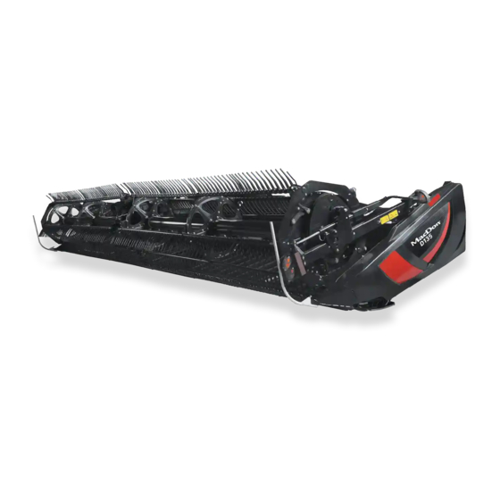
PRODUCT OVERVIEW 2.2 Component Identification Operating and maintaining the header requires understanding the names of its parts and their locations. Figure 2.1: Windrower Header Components A - Reel Cam B - Reel Tines C - Draper D - Center Reel Arm Prop Handle E - Hydraulic Connections F - Transport Light G - Reel Safety Prop... -
Page 42: Specifications
PRODUCT OVERVIEW 2.3 Specifications Here is a list of all the specifications for D1X and D1XL windrower-configured headers. The following symbol and letters are used in the table below: : optional (dealer installed) / –: not available S: standard / O : optional (factory installed) / O Table 2.1 Header Specifications Cutterbar... - Page 43 D125X D130XL, D135XL, Center-link extended 12.0° D140XL, D145XL Conveyor (Draper) and Decks Draper width (D1X Series) 1057 mm (41.6 in.) Draper width (D1XL Series) 1270 mm (50 in.) Draper drive Hydraulic Draper speed 225 m/min. (0–742 fpm) Delivery opening width (center delivery), variable by 4.6 m...
- Page 44 PRODUCT OVERVIEW Table 2.2 Header Attachments Upper Cross Auger Outside diameter 305 mm (12 in.) 152 mm (6 in.) Tube diameter All sizes Stabilizer Wheel / Slow Speed Transport Wheels 38 cm (15 in.) Tires P205/75 R-15 Table 2.3 Header Weights Weight Estimated weight range with base header (variances are due to different package configurations) D115X –...
-
Page 45: Dimensions
(long dividers removed) 2667 mm (105 in.) D1XL Series headers (long dividers installed) 2636 mm (104 in.) D1X Series headers (long dividers removed) 2452 mm (97 in.) D1X Series headers Header Height (Transport Mode, Reel Fore-Aft Fully Retracted) (long dividers installed) 2460 mm (97 in.) -
Page 47: Chapter 3: Operation
• It is your responsibility to read and understand this manual completely before operating the header. Contact your MacDon Dealer if an instruction is not clear to you. • Follow all safety messages in the manual and on safety decals on the machine. -
Page 48: Operational Safety
OPERATION 3.2 Operational Safety Follow all the safety and operational instructions given in this manual. CAUTION Adhere to the following safety precautions: • Follow all safety and operational instructions provided in your operator’s manuals. If you do not have a windrower manual, get one from your Dealer and read it thoroughly. -
Page 49: Reel Safety Props
OPERATION 3.2.2 Reel Safety Props The reel safety props are located on the reel support arms and prevent the reel from unexpectedly lowering. DANGER To prevent bodily injury or death from the unexpected start-up or fall of a raised machine, always stop the engine and remove the key before leaving the operator’s seat, and always engage the safety props before going under the machine for any reason. -
Page 50: Disengaging Reel Safety Props
OPERATION 4. Use handle (A) to move the lock rod to inboard position (B), which engages pin (C) under the prop. 5. Lower the reel until the safety props contact the outer arm cylinder mounts and the center arm pins. Figure 3.4: Reel Safety Prop –... -
Page 51: Header Endshields
OPERATION 4. Use handle (B) on double-reel headers to move lock rod (A) to the outboard position. Figure 3.6: Reel Safety Prop – Center Arm 3.2.3 Header Endshields A hinged, polyethylene endshield is fitted on each end of the header. Opening Endshields The endshields can be opened to access serviceable components or stored items. -
Page 52: Closing Endshields
OPERATION 4. Pull the endshield at handle depression (A). NOTE: The endshield is retained by hinge tab (B) and will open in direction (C). Figure 3.8: Left Endshield 5. If additional clearance is required, pull the endshield free of hinge tab (A) and swing the endshield toward the rear of the header. -
Page 53: Removing Endshields
To ensure the endshields are removed correctly, follow the recommended removal procedure provided here. NOTE: A D1X Series Draper Header is shown in the illustration. A D1XL Series Draper Header is similar. 1. Fully open the endshield. For instructions, refer to... -
Page 54: Checking And Adjusting Endshields
NOTE: Endshields may expand or contract when subjected to large temperature changes. The top pin and lower latch bracket Figure 3.13: Left Endshield on D1X Series positions can be adjusted to compensate for dimensional Draper Header changes. For instructions, refer to... - Page 55 2. Inside the endshield, loosen four bolts (A) on support tube bracket (B). NOTE: A D1X Series Draper Header is shown in the illustration. The endshield on a D1XL Series Draper Header is similar. Figure 3.15: Left Endshield Support Tube on D1X Series Header 3.
-
Page 56: Daily Start-Up Check
OPERATION 3.2.4 Daily Start-Up Check Perform daily start-up checks daily before operating the machine. CAUTION • Clear the area of other persons, pets, etc. Keep children away from machinery. Walk around the machine to be sure no one is under, on, or close to it. •... -
Page 57: Break-In Period
OPERATION 3.3 Break-in Period A brand-new machine must be operated gently when it is run for the first time. NOTE: Until you become familiar with the sound and feel of your new header, be extra alert and attentive. WARNING Before investigating an unusual sound or attempting to correct a problem, shut off the engine and remove the key from the igniation. -
Page 58: Shutting Down The Windrower
OPERATION 3.4 Shutting down the Windrower Before leaving the operator's seat for any reason, shut down the windrower. DANGER To prevent injury or death from the unexpected start-up of the machine, always stop the engine and remove the key from the ignition before leaving the operator’s seat for any reason. To shut down the windrower, do the following: 1. -
Page 59: Cab Controls
OPERATION 3.5 Cab Controls The header is controlled from the windrower cab. WARNING Be sure all bystanders are clear of the machine before starting the engine or engaging any header drives. For instructions, refer to your windrower operator’s manual for identification of the following in-cab controls: •... -
Page 60: Header Setup
Perform the following procedures before operating the machine for optimal performance. 3.6.1 Header Attachments Optional attachments can improve performance in specific conditions or add features to the header. Optional attachments can be ordered and installed by your MacDon Dealer. Refer to 6 Options and Attachments, page 243 for descriptions of available items. - Page 61 OPERATION 215651 Revision B...
- Page 62 OPERATION 215651 Revision B...
- Page 63 OPERATION 215651 Revision B...
- Page 64 OPERATION 215651 Revision B...
- Page 65 OPERATION 215651 Revision B...
- Page 66 OPERATION 215651 Revision B...
- Page 67 OPERATION 215651 Revision B...
- Page 68 OPERATION 215651 Revision B...
- Page 69 OPERATION 215651 Revision B...
-
Page 70: Reel Settings
OPERATION 3.6.3 Reel Settings The reel cam setting and reel position can be adjusted to produce different reel finger patterns. Table 3.11, page 56 illustrates the profile of the reel at each cam or finger pitch setting as well as the reel position relative to the ground at different positions on the reel arm. - Page 71 OPERATION Table 3.11 Recommended Reel Settings (continued) Cam Setting Number Reel Finger Pattern Reel Position Number (Finger Speed Gain) 3 (30%) 6 or 7 4 (35%) 2 or 3 NOTE: • Adjust the reel forward to get closer to the ground while tilting the header back. Fingers/tines will dig into the ground at extreme reel-forward positions, so adjust skid shoes or header angle to compensate.
-
Page 72: Header Operating Variables
OPERATION 3.7 Header Operating Variables Satisfactory function of the header requires making proper adjustments to suit various crops and conditions. Correct operation reduces crop loss and increases productivity. As well, proper adjustments and timely maintenance will increase the length of service you receive from your machine. The variables listed in Table 3.12, page 58 and detailed on the following pages will affect the performance of your header. - Page 73 OPERATION 1. Raise the header so that the stabilizer wheels are off the ground. 2. Shut down the engine and remove the key. 3. Check that the float is working properly. Refer to your windrower operator’s manual for instructions. CAUTION Handle may be under tension, especially when the wheels are on the ground.
- Page 74 OPERATION 14. Lower the header to the desired cutting height using the windrower controls. 15. Check the load indicator. Figure 3.21: Load Indicator IMPORTANT: Continuous operation with excessive spring compression (that is, a load indicator reading greater than 4 or a compressed length [A] less than 295 mm [11 5/8 in.]) can result in damage to the suspension system.
-
Page 75: Cutting On The Ground
OPERATION 4. Support the wheel weight by lifting slightly with one hand on handle (B), and pull up on handle (A) to release the lock. 5. Lift the wheel using handle (B), and engage the support channel into center slot (C) in the upper support. 6. - Page 76 OPERATION The header float system floats the header over the surface to compensate for ridges, trenches, and other variations in ground contour to prevent the cutterbar from pushing into the ground or leaving uncut crop. Refer to the following for additional information: •...
-
Page 77: Header Float
OPERATION 10. Check the header float as described in your windrower operator’s manual. Figure 3.27: Outer Skid Shoe 3.7.2 Header Float Headers are designed to ride on skid shoes while cutting on the ground. The windrower float system, however, reduces the ground pressure at the cutterbar allowing the header to float over obstacles and follow ground contours instead of being supported by the windrower lift cylinders. -
Page 78: Adjusting Header Angle
OPERATION Set the header angle according to the type and condition of crop and soil as follows: • Use shallower settings (A) (position A on the indicator) for normal cutting conditions and wet soil to reduce soil buildup at the cutterbar. Shallow angle settings also minimize damage to the knife in stony fields. -
Page 79: Optional Reel Drive Sprockets
Other sprockets are available that provide more torque to the reel in heavy cutting conditions or that allow for higher reel speeds in light crops when operating at increased ground speeds. See your MacDon Dealer for ordering information. For installation details, refer to 5.9.3 Reel Drive Sprocket, page... -
Page 80: Draper Speed
OPERATION Example: A 7.6 m (25 ft.) header operating at a ground speed of 9.7 km/h (6 mph) would produce a cut area of approximately 7.3 hectares (18 acres) in one hour. 3.7.6 Draper Speed Operating with the correct draper speed is an important factor for achieving good flow of cut crop away from the cutterbar. -
Page 81: Reel Fore-Aft Position
OPERATION • Grain stalks dropping ahead of the cutterbar For recommended reel heights for specific crops and crop conditions, refer to 3.6.2 Header Settings, page IMPORTANT: Maintain adequate clearance to prevent fingers contacting the knife or the ground. For instructions, refer to 5.8.1 Reel-to- Cutterbar Clearance, page 198. -
Page 82: Reel Tine Pitch
OPERATION 3.7.10 Reel Tine Pitch The reel is designed to pick up flattened and severely lodged crops. Because the cam setting is mainly used to determine how the crop gets delivered onto the drapers, it is not always necessary to increase the tine pitch (select a higher cam setting) to pick up lodged crops. - Page 83 OPERATION Cam Position 3, Reel Position 6 or 7 is mainly used to leave long stubble. • This position allows the reel to reach forward and lift the crop across the knife and onto the drapers. • This setting generates a fingertip speed that is approximately 30% faster than the reel speed.
-
Page 84: Adjusting Reel Cam
OPERATION Adjusting Reel Cam The reel is designed to pick up flattened and severely lodged crops. Adjustment may be required as crop conditions change. DANGER To prevent injury or death from the unexpected start-up of the machine, always stop the engine and remove the key from the ignition before leaving the operator’s seat for any reason. -
Page 85: Removing Crop Dividers Without Latch Option From Header
OPERATION 6. Lift safety lever (A). 7. Hold onto crop divider (B), push lever (C) to open the latch, and lower the crop divider. Figure 3.39: Crop Divider 8. Lift the crop divider off of the endsheet and store it as follows: Insert pin (A) on the crop divider into the hole in the endsheet at the location shown. -
Page 86: Installing Crop Dividers With Latch Option Onto Header
OPERATION 6. Remove bolt (A), the lock washer, and the flat washer. 7. Lower crop divider (B), then lift it to remove it from the endsheet. 8. Close the endshield. For instructions, refer to Closing Endshields, page Figure 3.41: Crop Divider Installing Crop Dividers with Latch Option onto Header To correctly install crop dividers with the latch option, follow the recommended installation procedure provided here. -
Page 87: Installing Crop Dividers Without Latch Option Onto Header
OPERATION 7. Position the crop divider as shown by inserting lugs (A) into the holes in the endsheet. 8. Lift the forward end of the crop divider until pin (B) at top of the crop divider engages and closes latch (C). 9. - Page 88 OPERATION 5. Open the endshield. For instructions, refer to Opening Endshields, page 6. If the crop divider is stored on the header, remove the crop divider from the storage location by lifting the crop divider to disengage lugs (A) at the lower end and then lowering it slightly to disengage pin (B) from the endsheet.
-
Page 89: Crop Divider Rods
OPERATION 3.7.12 Crop Divider Rods Removable crop divider rods are used in conjunction with crop dividers to help divide the crop when harvesting. The rods are most useful when crop is bushy or down. In standing crops, using only crop dividers is recommended. Table 3.15 Crop Divider Rods Recommended Use With Divider Rods Without Divider Rods... -
Page 90: Installing Crop Divider Rods
OPERATION Installing Crop Divider Rods To install the crop divider rods onto the crop dividers, perform the installation procedure provided here. 1. Remove crop divider rods (A) from their storage location on the inboard of the side endsheet. Figure 3.50: Right Endsheet 2. -
Page 91: Delivery Opening
OPERATION 3.8 Delivery Opening The width and location of the delivery opening affects the width and configuration of the windrow. The decision to widen or narrow the center delivery opening, or to double windrow, should be based on the following factors: •... -
Page 92: Adjusting Delivery Opening On Header Using Hydraulic Deck Shift
OPERATION 3.8.2 Adjusting Delivery Opening on Header using Hydraulic Deck Shift The width and position of the delivery opening affects the width and configuration of the windrow. Adjust the delivery opening by moving the inboard deck shift stops. Adjusting inboard deck shift stop 1. -
Page 93: Double Windrowing
OPERATION 3.9 Double Windrowing Double windrowing involves laying two windrows side-by-side. Larger capacity combines or forage harvesters can then pick up twice as much material in a single pass which saves time and fuel. Double windrowing is used for crops that don’t require conditioning such as grains, canola, and beans. Double windrowing is performed using the header’s deck shifting ability. -
Page 94: Windrow Types
OPERATION 3.10 Windrow Types Crops can be laid into six types of windrows depending on crop conditions, machine settings, and weather conditions. The following criteria determine windrow quality: • Weight Distribution: Heads and stalks distributed evenly across full width of windrow. •... - Page 95 OPERATION Table 3.16 Windrow Types (continued) Weight Machine Setting Description Curing Windrow Type Weatherability Distribution Guidelines The stalks are lined • Low reel 45° diagonal along one edge and speed heads are lined along • Less opposite edge, 45° to windrow perpendicular.
-
Page 96: Haying Tips
OPERATION 3.11 Haying Tips Refer to the following tips to optimize haying. 3.11.1 Curing Curing crops quickly helps maintain the highest quality because for each day that hay lies on the ground, 5% of the protein is lost. Leaving the windrow as wide and fluffy as possible results in the quickest curing. Cured hay should be baled as soon as possible. -
Page 97: Driving On Windrow
OPERATION Table 3.18 Recommended Windrow Characteristics Advantage Characteristic Enables airflow through windrow which is more important to the curing High and fluffy process than direct sunlight Consistent formation (not bunching) Permits an even flow of material into the baler, chopper, etc. Results in even and consistent bales to minimize handling and Even distribution of material stacking problems... -
Page 98: Levelling The Header
OPERATION 3.12 Levelling the Header The windrower linkages are factory-set to provide the proper level for the header and should not normally require adjustment. NOTE: The float springs are NOT used to level the header. If the header is not level, check the pressure of the windrower’s tires to ensure proper inflation (refer to your windrower operator’s manual). -
Page 99: Unplugging The Cutterbar
OPERATION 3.13 Unplugging the Cutterbar The cutterbar is located on the front of the header. It supports the knife and guards which are used to cut the crop. DANGER To prevent bodily injury or death from the unexpected start-up or fall of a raised machine, always stop the engine and remove the key before leaving the operator’s seat, and always engage the safety props before going under the machine for any reason. -
Page 100: Upper Cross Auger
OPERATION 3.14 Upper Cross Auger The upper cross auger (UCA) (A) improves delivery of very bulky crops across the header. The UCA is available as an optional kit. For more information, refer to 6.4.3 Upper Cross Auger, page 253. NOTE: Optional wide draper deflectors are NOT compatible with the UCA. -
Page 101: Transporting Header
• Travel at safe speeds to ensure complete machine control and stability at all times. 3.15.2 Towing Headers with the Transport/Stabilizer Wheel option can be towed behind a properly configured MacDon windrower or an agricultural tractor. For instructions, refer to the windrower operator’s manual. -
Page 102: Attaching Header To Towing Vehicle
• Connect the header seven-pole plug wiring harness to the mating receptacle on the towing vehicle (the seven-pole receptacle is available from your MacDon Dealer parts department.) • Ensure all lights are functioning properly, and clean the slow moving vehicle sign and other reflectors. Use flashing warning lights unless prohibited by law. -
Page 103: Converting From Transport To Field Position
OPERATION 3.15.3 Converting from Transport to Field Position To convert from transport position to field position, follow all the recommended procedures provided here. Removing Tow-Bar Perform the following procedure to remove the tow-bar. DANGER To prevent bodily injury or death from the unexpected start-up of the machine, always stop the engine and remove the key before making adjustments to the machine. -
Page 104: Storing Tow-Bar
OPERATION 6. Remove clevis pin (A) and set aside for reinstallation. 7. Push latch (B) and lift tow-bar (C) from the hook. Release latch. 8. Install clevis pin (A). Figure 3.60: Tow-Bar Latch Storing Tow-Bar Perform the following procedure to store the tow-bar. The tow-bar consists of two sections, an inner half (A) and an outer half (B);... - Page 105 OPERATION 1. Place the inner end of the outer half of the tow-bar into the cradle (A) on the left side of the header backtube. 2. Secure the clevis/pintle end of the tow-bar in support (B) on the endsheet using hitch pin (C). Secure with a lynch pin. 3.
-
Page 106: Moving Front (Left) Wheels Into Field Position
OPERATION 5. At the right end of the 9.1 m (30 ft.) header: Place the inner end of the inner half of the tow-bar in cradle (A) on header backtube. b. Secure tube end in support (B) with pin (C). Install rubber strap on cradle (A). - Page 107 OPERATION 4. Swivel the front wheel assembly (A) so the wheels are aligned with the lower frame. 5. Remove pin (B) and pull the wheel assembly towards the rear of the header. Store the pin in hole (C) at the top of the leg.
-
Page 108: Moving Rear (Right) Wheels Into Field Position
OPERATION 9. Lift the wheel assembly to the desired height and slide linkage (A) into the appropriate slot in the vertical support. 10. Push down on handle (B) to lock. Figure 3.67: Front Wheels Moving Rear (Right) Wheels into Field Position Perform the following procedure to move the rear (right) wheels into field position. - Page 109 OPERATION 5. Remove pin (A) and store at location (B). 6. Pull handle (C) upwards to release. 7. Lift the wheel to the desired height, and engage the support channel into slot (D) in the vertical support. 8. Push down on handle (C) to lock. Figure 3.69: Rear Wheel –...
-
Page 110: Converting From Field To Transport Position
OPERATION 12. Pull pin (A) on the right axle, swivel the wheel counterclockwise to the position shown, and lock with pin (A). 13. Remove hairpin (B) from latch (C). 14. Lift the wheel, lift latch (C), and engage lug (D) onto the left axle. - Page 111 OPERATION 1. Pull handle (B) upwards to release and raise linkage (A) fully upwards into the vertical support. 2. Raise the header fully. 3. Shut down the engine, and remove the key from the ignition. 4. Engage the header’s safety props. Figure 3.73: Suspension Linkage 5.
-
Page 112: Moving Rear (Right) Wheels Into Transport Position
OPERATION 9. Remove pin (A) from storage at the top of leg (B). 10. Move and swivel the wheels clockwise until connector (C) is turned towards the front end of the header. 11. Insert pin (A) and turn to lock. 12. - Page 113 OPERATION 6. Remove pin (A) and install at location (B) to secure the linkage. Turn the pin to lock. 7. Pull pin (D), swivel wheel (C) counterclockwise 90 degrees, and release the pin to lock. Figure 3.78: Wheel Position 8. Ensure the left wheel is in the transport position as shown. Figure 3.79: Left Wheel in Transport Position 9.
- Page 114 OPERATION 10. Lock the wheel (A) with pin (B). Move the right axle (C) to the front of the header. Figure 3.81: Right Rear Wheel 11. Remove the pin (A), raise support (B) to the position shown, and reinsert pin. IMPORTANT: Ensure the pin (A) engages the tube on the axle.
-
Page 115: Attaching Tow-Bar
OPERATION Attaching Tow-Bar The tow-bar consists of two sections making for easier storage and handling. 1. Unhook rubber strap (D) from cradle (A) on the right side of the header. 2. Remove clevis pin (C) and detach the tube end from support (B). - Page 116 OPERATION 8. Connect outer half (B) of the tow-bar to inner half (A). Figure 3.85: Tow-Bar Assembly 9. Lift outer half (B) and insert it into inner half (A). Figure 3.86: Tow-Bar Assembly 10. Secure the two halves together with L-pin (A) and then turn to lock.
- Page 117 OPERATION 12. Position tow-bar (A) onto the axle, and push against latch (B) until the tow-bar pins drop into hooks (C). 13. Check that latch (B) has engaged the tow-bar. 14. Install clevis pin (D) and secure with hairpin. Figure 3.88: Attaching Tow-Bar 15.
-
Page 119: Chapter 4: Header Attachment/Detachment
This chapter includes instructions for setting up, attaching, and detaching the header. IMPORTANT: When attaching a D1X Series Draper Header to an M1 Series Windrower that has been previously configured for an R216 SP Rotary Disc Header, remove two shield mount plates (A) (MD #307045) from the forming shield before attaching the draper header to the windrower. - Page 120 HEADER ATTACHMENT/DETACHMENT 3. All draper headers except D115X: Push lever (A) up and pull arm (B) to get pin (C) out of latch (D). Figure 4.3: Hydraulic Hose Management System – All Headers Except D115X 4. D115X Draper Headers: Pull hydraulic hose management system (A) towards the left outboard end of the header, disengage ball stud (B) from the cradle in support (C).
- Page 121 HEADER ATTACHMENT/DETACHMENT 6. Check the connectors and ensure they are clean before connecting the hydraulics and electrical harnesses. 7. Retrieve draper drive and reel control multicoupler (A) from the hydraulic hose management system. 8. Push knob (B) on the hydraulic receptacle and pull handle (C) fully away from the windrower.
- Page 122 HEADER ATTACHMENT/DETACHMENT 15. Ensure the hydraulic hose routing is as straight as possible and avoid potential rub/wear points. Figure 4.9: Hydraulic Multicouplers and Hose Routing 215651 Revision B...
-
Page 123: Detaching Header From M1 Series Windrowers
HEADER ATTACHMENT/DETACHMENT 4.2 Detaching Header from M1 Series Windrowers To detach the header from an M1 Series Windrower, follow the recommended detachment procedure provided here. DANGER To prevent bodily injury or death from the unexpected startup of the machine, always stop the engine and remove the key from the ignition before leaving the operator’s seat for any reason. - Page 124 HEADER ATTACHMENT/DETACHMENT 11. Disconnect hydraulic hose management system (A) from the left outer leg of the windrower by pulling ball stud latch handle (C) to disengage ball stud (B) from the support. NOTE: The hydraulic hoses have been removed from the illustration for clarity.
- Page 125 HEADER ATTACHMENT/DETACHMENT 14. Swing the left windrower platform forwards. For instructions, refer to the windrower operator’s manual. 15. Detach the header from the windrower. For instructions, refer to the windrower operator’s manual. Figure 4.15: Left Windrower Platform 215651 Revision B...
-
Page 127: Chapter 5: Maintenance And Servicing
Chapter 5: Maintenance and Servicing Information necessary to perform routine maintenance and occasional servicing tasks on your machine is provided here. The word “maintenance” refers to scheduled tasks that help your machine operate safely and effectively; “Service” refers to tasks that must be performed when a part needs to be repaired or replaced. For advanced service procedures, contact your Dealer. -
Page 128: Maintenance Specifications
1. Shut down the engine, and remove the key from the ignition. 2. Position the ends of the chain onto the sprocket. 3. Install the pin connector (A) (not available as a MacDon part) into the chain (preferably from backside of sprocket). - Page 129 MAINTENANCE AND SERVICING 7. Loosen the flangette bolts on the mating bearing (one turn) and then retighten. This will allow the bearing to properly line up. 215651 Revision B...
-
Page 130: Maintenance Requirements
MAINTENANCE AND SERVICING 5.3 Maintenance Requirements Periodic maintenance requirements are organized according to service intervals. Regular maintenance is the best insurance against early wear and untimely breakdowns. Following the maintenance schedule will increase your machine’s life. When servicing the machine, refer to the specific headings in this section and use only fluids and lubricants specified in the Recommended Fluids and Lubricants section on the inside back cover of this manual. -
Page 131: Break-In Inspection
MAINTENANCE AND SERVICING Knife Drive Box Lubricant (First 50 Hours Only) - Refer to 5.6.1 Knife Drive Box, page 146. 250 Hours Draper Seal - Refer to 5.7.2 Installing ü Drapers, page 175. Reel Drive U-Joint - Refer to 5.9 Reel Drive, page 225. -
Page 132: Preseason Servicing
MAINTENANCE AND SERVICING 5.3.3 Preseason Servicing Perform the following procedures at the beginning of each operating season: CAUTION • Review this manual to refresh your memory on the safety and operating recommendations. • Review all the safety decals and other decals on the header and note the hazard areas. •... -
Page 133: Checking Hydraulic Hoses And Lines
MAINTENANCE AND SERVICING 12. Replace or tighten any missing or loose hardware. For instructions, refer to 9.1 Torque Specifications, page 273. 5.3.5 Checking Hydraulic Hoses and Lines Check hydraulic hoses and lines daily for signs of leaks. WARNING • Avoid high-pressure fluids. Escaping fluid can penetrate the skin causing serious injury. -
Page 134: Lubrication
MAINTENANCE AND SERVICING 5.3.6 Lubrication Greasing points are marked on the machine by decals showing a grease gun and the grease interval in hours of operation. Refer to the inside back cover for recommended lubricants. Log hours of operation and use the Maintenance Record provided to keep a record of scheduled maintenance. -
Page 135: Lubrication Service Intervals
MAINTENANCE AND SERVICING Lubrication Service Intervals Lubricate the components detailed in the following lubrication service intervals for optimal performance. Every 10 Hours Lubricate the following components every 10 hours unless otherwise stated. Use high temperature extreme pressure (EP2) performance grease with 1% max molybdenum disulphide (NLGI Grade 2) lithium base unless otherwise specified. - Page 136 MAINTENANCE AND SERVICING Every 25 Hours Lubricate the following components every 25 hours unless otherwise stated. Use high temperature extreme pressure (EP2) performance grease with 1% max molybdenum disulphide (NLGI Grade 2) lithium base unless otherwise specified. Knifehead: Lubricate the knifehead (A) every 25 hours. Check for signs of excessive heating on the first few guards after greasing.
- Page 137 MAINTENANCE AND SERVICING Every 100 Hours Lubricate the following components every 100 hours unless otherwise stated. NOTE: Use High Temperature Extreme Pressure (EP2) Performance with 1% max molybdenum disulphide (NLGI Grade 2) lithium base unless otherwise specified. Figure 5.10: Every 100 Hours A - Knife Drive Box (Check Oil Level with Top of Knife Drive Box in Horizontal Position) B - Dipstick (Level between Lower Hole and End of Dipstick) C - Upper Cross Auger Bearing...
- Page 138 MAINTENANCE AND SERVICING Every 250 Hours Lubricate the following components every 250 hours unless otherwise stated. NOTE: Use High Temperature Extreme Pressure (EP2) Performance with 1% max molybdenum disulphide (NLGI Grade 2) lithium base unless otherwise specified. Figure 5.11: Every 250 Hours A - Upper Cross Auger U-Joint 75 B - Upper Cross Auger Bearing (Two Places) 76 75.
- Page 139 MAINTENANCE AND SERVICING NOTE: Use High Temperature Extreme Pressure (EP2) Performance with 1% Max molybdenum disulphide (NLGI Grade 2) lithium base unless otherwise specified. Figure 5.12: Every 250 Hours A - Front Wheel Pivot B - Frame/Wheel Pivot (Both Sides) C - Double Reel U-Joint 77 77.
- Page 140 MAINTENANCE AND SERVICING Every 500 Hours Lubricate the following components every 500 hours unless otherwise stated. NOTE: Use High Temperature Extreme Pressure (EP2) Performance with 1% max molybdenum disulphide (NLGI Grade 2) lithium base unless otherwise specified. Figure 5.13: Every 500 Hours A - Reel –...
-
Page 141: Electrical System
(D130XL) Identification Number, Branch location Header identification (D135XL) Header identification (D140XL and D145XL) Draper speed (left) Draper speed (right) Table 5.2 D1X Series Wire Prefix Identification Prefix System D1 Series main harness D1 Series reel extension harness 215651 Revision B... -
Page 142: Replacing Light Bulbs
MAINTENANCE AND SERVICING Table 5.2 D1X Series Wire Prefix Identification (continued) System Prefix Hydraulic deck shift Auger/draper adapter Color codes apply to actual wire colors on the header. For the color code legend, refer to Table 5.3, page 128. Wire example, XXXXXXX N18: The wire color (A) is brown and the wire gauge (B) is 18. -
Page 143: Checking And Adjusting Reel Height Sensor
MAINTENANCE AND SERVICING 2. Use a Phillips screwdriver to remove screws (A) from the fixture, and remove the plastic lens. Retain screws (A). 3. Replace the bulb, and reinstall the plastic lens and screws. NOTE: Use trade #1156 bulb for amber transport lights and #1157 for red tail lights. - Page 144 MAINTENANCE AND SERVICING 1. Shut down the engine, and remove the key from the ignition. 2. Check that sensor arm (A) and pointer (B) are configured properly for your machine. NOTE: The sensor arm is semitransparent in the illustration to show the sensor pointer behind it.
- Page 145 MAINTENANCE AND SERVICING 4. Use the windrower display or a voltmeter (if measuring the sensor manually) to measure voltage range Y. Refer to Table 5.4, page 130 for range requirements. 5. If using a voltmeter, measure the voltage between the ground wire (pin 2) and the signal wire (pin 3) at the reel height sensor (B).
-
Page 146: Cutterbar
MAINTENANCE AND SERVICING 5.5 Cutterbar The cutterbar is located on the front of the header. It supports the knife and guards which is used to cut the crop. WARNING Keep hands clear of the area between guards and knife at all times. -
Page 147: Spare Knife
Ensure the spare knife is secured in place. If there is no spare knife in the header backtube, individual knife sections can be ordered from your MacDon Dealer Parts Department. Figure 5.24: Spare Knife... -
Page 148: Removing Knife
MAINTENANCE AND SERVICING 5.5.3 Removing Knife To remove the knife, perform the recommended removal procedure provided here. DANGER To prevent bodily injury or death from the unexpected start-up of the machine, always stop the engine and remove the key before making adjustments to the machine. WARNING To prevent bodily injury from the fall of a raised reel, always engage the reel safety props before going under the raised reel for any reason. -
Page 149: Installing Knifehead Bearing
MAINTENANCE AND SERVICING WARNING To prevent bodily injury from the fall of a raised reel, always engage the reel safety props before going under the raised reel for any reason. WARNING Stand to the rear of the knife during removal to reduce the risk of injury from cutting edges. Wear heavy gloves when handling the knife. -
Page 150: Installing Knife
MAINTENANCE AND SERVICING IMPORTANT: To prevent premature knifehead or knife drive box failure, ensure there is a tight fit between the knifehead pin and the needle bearing, and between the knifehead pin and the output arm. 4. Install the knife. For instructions, refer to 5.5.6 Installing Knife, page 136. -
Page 151: Knife Guards
NOTE: Use guard straightening tool (MD #140135) available from your MacDon Dealer. 1. Shut down the engine, and remove the key from the ignition. 2. Position tool (A) as shown, and pull up to adjust the guard tips upwards. -
Page 152: Replacing Pointed Guards
NOTE: If material is tough to cut, install short knife guards with top guard and adjuster plate. A kit is available from your MacDon Dealer. For more information, refer to 6.2.4 Stub Guard Conversion Kit, page 247. -
Page 153: Replacing Stub Knife Guards
MAINTENANCE AND SERVICING IMPORTANT: The first four outboard guards (B) on the drive sides of the header do NOT have ledger plates. Ensure proper replacement guards are installed at these locations. Figure 5.33: Pointed Guards A - Standard B - Drive Side 5. - Page 154 MAINTENANCE AND SERVICING 2. Stroke the knife manually until the knife sections are spaced midway between the guards. 3. Remove two nuts (A) and bolts attaching guard (B) and top guide (C) to the cutterbar. 4. Remove guard (B), the plastic wearplate (if installed), top guide (C), and adjuster bar (D).
-
Page 155: Knife Hold-Downs
MAINTENANCE AND SERVICING 5. Position the plastic wearplate (if applicable), replacement guard (B), adjuster bar (D), and top guide (C), and then install bolts and nuts (A). Do NOT tighten. 6. Check and adjust the clearance between the hold-downs and the knife. For instructions, refer to Checking and Adjusting Hold-Down with Stub Guards, page 143. -
Page 156: Checking And Adjusting Hold-Down At Double-Knife Center Pointed Guard
MAINTENANCE AND SERVICING 2. Use a feeler gauge to measure the clearance between the standard guard hold-down (A) and the knife section. Ensure the clearance is 0.1–0.6 mm (0.004–0.024 in.). 3. To lower the front of the hold-down and decrease clearance, turn bolt (B) clockwise;... -
Page 157: Checking And Adjusting Hold-Down With Stub Guards
MAINTENANCE AND SERVICING 2. Use a feeler gauge to measure the clearance between the center guard hold-down (A) and the knife section. Ensure the clearance is between the following measurements: • At hold-down tip (B): 0.1–0.4 mm (0.004–0.016 in.) • At rear of hold-down (C): 0.1–1.0 mm (0.004–0.040 in.) 3. -
Page 158: Knifehead Shield
MAINTENANCE AND SERVICING 2. Use a feeler gauge to measure the clearance between stub guard hold-down (A) and the knife section. Ensure the clearance is between the following measurements: • At hold-down tip (B): 0.1–0.4 mm (0.004–0.016 in.) • At rear of hold-down (C): 0.1–1.0 mm (0.004–0.040 in.) 3. - Page 159 MAINTENANCE AND SERVICING 1. Raise the reel to its full height, and lower the header to the ground. 2. Shut down the engine, and remove the key from the ignition. 3. Engage the reel safety props. For instructions, refer to Engaging Reel Safety Props, page 4.
-
Page 160: Knife Drive System
MAINTENANCE AND SERVICING 5.6 Knife Drive System The knife drive system transforms pumped hydraulic pressure into a mechanical motion that stokes a series of serrated knife blades at the front of the header back and forth to cut a variety of crops. 5.6.1 Knife Drive Box The knife drive box is an enclosed oil bath with a 76.2 mm (3 in.) stroke. -
Page 161: Removing Knife Drive Box
MAINTENANCE AND SERVICING Removing Knife Drive Box The knife drive box may need to be removed for repair at the Dealership. To remove the knife drive box, follow the recommended removal procedure provided here. DANGER To prevent bodily injury or death from the unexpected start-up of the machine, always stop the engine and remove the key before making adjustments to the machine. - Page 162 MAINTENANCE AND SERVICING For untimed headers: 7. Loosen two bolts (A) securing the motor assembly to the header endsheet. 8. Loosen the belt tension by turning tensioning bolt (B) counterclockwise. Figure 5.48: Untimed Double-Knife Drive For both timed and untimed headers: 9.
-
Page 163: Removing Knife Drive Box Pulley
MAINTENANCE AND SERVICING 12. Manually stroke the knife to its outer limit. 13. Clean the area around the knifehead. 14. Remove grease fitting (B) from the pin. NOTE: Removing the grease fitting will make it easier to reinstall the knifehead pin later. 15. -
Page 164: Installing Knife Drive Box Pulley
MAINTENANCE AND SERVICING 1. Loosen and remove knife drive box pulley clamping bolt (A) and nut (B). 2. Using a three-jaw puller, remove knife drive box pulley (C). Figure 5.53: Knife Drive Box and Pulley Installing Knife Drive Box Pulley The knife drive box pulley is driven by the knife drive motor and the knife drive belt. -
Page 165: Installing Knife Drive Box
MAINTENANCE AND SERVICING Installing Knife Drive Box To install a knife drive box, follow the recommended installation procedure provided here. NOTE: If the pulley was removed from the knife drive box, refer to Installing Knife Drive Box Pulley, page 150. If the pulley was NOT removed, proceed to Step 1, page 151. - Page 166 MAINTENANCE AND SERVICING 6. Position output arm (A) to the farthest outboard position. 7. Move output arm (A) up or down on the splined shaft until it is almost contacting knifehead (B) (exact clearance [C] is set during the knifehead pin installation). Figure 5.58: Knifehead 8.
- Page 167 17. Move the output arm to the mid-stroke position, and ensure the knife bar doesn’t contact the front of the first guard. If the knife drive box requires adjustment, contact your MacDon Dealer. 18. Install and tension the knife drive belts. • For untimed headers, refer to...
- Page 168 MAINTENANCE AND SERVICING 3. Place a straight edge (A) along the face of knife drive box pulley (B) and measure a distance of 1000 mm (39 3/8 in.) between point (C) and point (D). 4. Measure distance (E) between the straight edge and the endsheet at point (C) and point (D).
- Page 169 MAINTENANCE AND SERVICING NOTE: The procedure is the same for both ends of a timed double-knife header. Images shown are for the left end—the right end is opposite. 2. Shut down the windrower, and remove the key from the ignition. 3.
- Page 170 MAINTENANCE AND SERVICING 9. Move the output arm to the mid-stroke position, and adjust the knife drive box until there is a 1–2 mm (1/32–1/16 in.) gap (B) between the front of knife bar (A) and guard (C). NOTE: If knife bar (A) makes contact with the front of guard (C), move the knife drive box rearwards.
-
Page 171: Changing Oil In Knife Drive Box
MAINTENANCE AND SERVICING Changing Oil in Knife Drive Box Change the knife drive box lubricant after the first 50 hours of operation and every 1000 hours (or 3 years) thereafter. DANGER To prevent bodily injury or death from the unexpected start-up of the machine, always stop the engine and remove the key before making adjustments to the machine. - Page 172 MAINTENANCE AND SERVICING 1. Loosen two bolts (A) securing the motor assembly to the header endsheet. 2. Open the endshield. For instructions, refer to Opening Endshields, page Figure 5.73: Untimed Double-Knife Drive 3. Loosen two bolts (A) securing the motor assembly to the header endsheet.
- Page 173 MAINTENANCE AND SERVICING 6. Remove belt (A) from drive pulley (B). 7. Slip belt (A) over and behind knife drive box pulley (C). Use the notch in the pulley to assist with belt removal. Figure 5.76: Knife Drive Installing Untimed Double-Knife Drive Belts The procedure for installing untimed double-knife drive belts is the same for both sides of the header.
- Page 174 MAINTENANCE AND SERVICING 3. Tension the knife drive belt. For instructions, refer to Checking and Tensioning Untimed Double-Knife Drive Belts, page 160. 4. Install access cover (A) and secure with bolt. 5. Close the endshield. For instructions, refer to Closing Endshields, page Figure 5.78: Access Cover Checking and Tensioning Untimed Double-Knife Drive Belts...
-
Page 175: Timed Double-Knife Drive Belts
MAINTENANCE AND SERVICING 6. Ensure that the clearance between belt (A) and belt guide (B) is 1 mm (1/16 in.). 7. Loosen three bolts (C), and adjust the position of guide (B) as needed. 8. Tighten three bolts (C). 9. Close the endshield. For instructions, refer to Closing Endshields, page NOTE:... - Page 176 MAINTENANCE AND SERVICING DANGER To prevent bodily injury or death from the unexpected start-up of the machine, always stop the engine and remove the key before making adjustments to the machine. 1. Shut down the engine, and remove the key from the ignition.
- Page 177 MAINTENANCE AND SERVICING Removing Timed Knife Drive Belt The timed knife drive belt removal procedure is the same for both sides of the header. DANGER To prevent bodily injury or death from the unexpected start-up of the machine, always stop the engine and remove the key before making adjustments to the machine.
- Page 178 MAINTENANCE AND SERVICING 6. Left drive ONLY: Loosen two bolts (A) on the endsheet. 7. Left drive ONLY: Turn adjuster bolt (B) counterclockwise to loosen, and remove two V-belts (C). Figure 5.85: Knife Drive V-Belts 8. Open access cover (A) on the endsheet behind the cutterbar to provide clearance between the knife drive box pulley and the endsheet.
- Page 179 MAINTENANCE AND SERVICING 1. Shut down the engine, and remove the key from the ignition. 2. Route knife drive belt (A) around pulley (B) and knife drive box pulley (C). NOTE: Ensure the drive motor is fully forward. Do NOT pry the belt over the pulley.
- Page 180 MAINTENANCE AND SERVICING For D1X headers only: 6. Ensure the knives are timed before tightening the belt. For instructions, refer to Adjusting Timed Double-Knife Timing, page 169. 7. Slide idler pulley (A) up the slot on support bracket (B) to take up the slack in the timing belt.
- Page 181 MAINTENANCE AND SERVICING Tensioning Timed Double-Knife Drive Belts The tension of the timed knife drive belts must be set correctly in order for the cutterbar’s knife sections to stroke properly. IMPORTANT: To ensure the service life of the belt and the knife drives, NEVER overtighten a drive belt. IMPORTANT: Do NOT use the adjuster bolt at the drive pulley to adjust the tension on the timing belt of a timed knife drive.
- Page 182 MAINTENANCE AND SERVICING 6. Tighten nuts (A) on idler pulleys (B) to 217 Nm (160 lbf·ft). Figure 5.94: Left Knife Drive Pulleys 7. Tighten jam nut (A) to lock the position of adjuster bolt (B). Figure 5.95: Left Knife Drive 8.
- Page 183 MAINTENANCE AND SERVICING Adjusting Timed Double-Knife Timing Timed double-knife drive headers (10.7 m [35 ft.] and smaller) require the knives to be properly timed to move in opposite directions. DANGER To prevent bodily injury or death from the unexpected start-up of the machine, always stop the engine and remove the key before making adjustments to the machine.
- Page 184 MAINTENANCE AND SERVICING 6. Install right belt (A). NOTE: Ensure the knife drive box drive pulley and driven pulley do NOT rotate during belt installation. Figure 5.99: Knife Drive – Right Side 7. Slide idler pulley (A) up by hand to remove most of the belt slack.
- Page 185 MAINTENANCE AND SERVICING 10. Tighten hex nuts (A) on idler pulleys (B). 11. To check for correct knife timing, rotate the drive slowly by hand, and observe where the knives overlap at the center of the header. IMPORTANT: The knives must begin moving at the exact same time, and must move in opposite directions.
- Page 186 MAINTENANCE AND SERVICING 5. If the belt is tracking towards the inboard side of the drive pulley, the likely cause is a toe-out problem (A) and (B). If the belt tends to move towards the low tension [inboard] side of the pulley, proceed to Step 8, page 173.
- Page 187 MAINTENANCE AND SERVICING 8. If there is a tracking problem on the drive pulley, adjust the position of the cross-shaft support tube as follows: Loosen nut (A) on support assembly (B). b. To correct a toe-out condition, slide support assembly (B) rearward in slot (C). To correct a toe-in condition, slide support assembly (B) forward.
- Page 188 MAINTENANCE AND SERVICING 10. If further adjustment is required to correct drive pulley tracking, proceed as follows: Loosen jam nuts (A). b. Loosen jam nut and adjuster bolt (B) to relieve belt tension. Loosen nuts (C) at the drive pulley location. d.
-
Page 189: Drapers
MAINTENANCE AND SERVICING 5.7 Drapers Two drapers convey cut crop to center opening. Replace drapers if torn, cracked, or missing slats. 5.7.1 Removing Drapers DANGER To prevent bodily injury or death from the unexpected start-up or fall of a raised machine, always stop the engine and remove the key before leaving the operator’s seat, and always engage the safety props before going under the machine for any reason. - Page 190 MAINTENANCE AND SERVICING 4. Shut down the engine, and remove the key from the ignition. 5. Engage the header safety props. 6. Engage the reel safety props. For instructions, refer to Engaging Reel Safety Props, page 7. Check the deck height before installing the drapers. For instructions, refer to 5.7.5 Adjusting Deck Height, page 181.
-
Page 191: Checking And Adjusting Draper Tension
MAINTENANCE AND SERVICING 15. Check clearance (A) between drapers (B) and cutterbar (C). Clearance should be 1–3 mm (1/16–1/8 in.). If adjustment is necessary, refer to 5.7.5 Adjusting Deck Height, page 181. Figure 5.113: Draper Seal 16. If backsheet deflector (A) requires adjustment, loosen nut (D) and move the deflector until there is a 1–7 mm (1/32–5/16 in.) gap (C) between draper (B) and the deflector. - Page 192 MAINTENANCE AND SERVICING 1. Locate the draper tension adjuster and the tension inspection window on the rear left side of the header. 2. Ensure that white indicator bar (A) is at the halfway point in the window. If this is not the case, then adjustment is required.
-
Page 193: Adjusting Draper Tracking
MAINTENANCE AND SERVICING 8. Ensure that idler roller (A) sits between draper guides (B). Figure 5.117: Idler Roller 9. To reduce the tension on the draper, turn adjuster bolt (A) counterclockwise. White indicator bar (B) will move outboard in the direction of arrow (D) to indicate that the tension on the draper has lessened. - Page 194 MAINTENANCE AND SERVICING Figure 5.119: Draper Tracking Overview A - Drive Roller B - Idler Roller C - Drive Roller Adjust D - Idler Roller Adjust E - Draper Direction 1. To determine which roller requires adjustment and which adjustments are necessary, refer to the following table: Table 5.5 Draper Tracking Tracking Adjustment Location...
-
Page 195: Adjusting Deck Height
MAINTENANCE AND SERVICING 3. Refer to Table 5.5, page 180 and adjust nut (C) to adjust the idler roller (either by increasing or decreasing its alignment) as follows: Loosen nut (A) and jam nut (B). b. Turn adjuster nut (C). NOTE: If the draper does not track at the idler roller end after the idler roller adjustment, the drive roller is likely not square to... - Page 196 MAINTENANCE AND SERVICING 1. Lower the header onto blocks. 2. Raise the reel fully. 3. Move reel safety props (A) to the engaged position. NOTE: Keep pivot bolt (B) sufficiently tight that the prop remains in the stored position when not in use, but can be engaged using hand force.
- Page 197 MAINTENANCE AND SERVICING 8. Ensure that clearance (A) between draper (B) and cutterbar (C) is 1–3 mm (0.04–0.12 in.). Figure 5.124: Draper Seal 9. Measure the clearance between the draper and the cutterbar at deck supports (A). Depending on the header size, there are between two and five supports per deck.
- Page 198 MAINTENANCE AND SERVICING 12. Loosen two lock nuts (A) on deck support (B) by one half-turn ONLY. NOTE: The deck is shown with the draper removed. The number of deck supports depends on the width of the header: • D115X and D120X: Four supports •...
- Page 199 MAINTENANCE AND SERVICING 22. If necessary, adjust backsheet deflector (A) by loosening nut (D) and moving the deflector until there is a 1–7 mm (0.04–0.28 in.) gap (indicated by callout [C]) between draper (B) and the deflector. WARNING Check to be sure all bystanders have cleared the area. 23.
-
Page 200: Replacing Draper Clips (Option)
MAINTENANCE AND SERVICING 5.7.6 Replacing Draper Clips (Option) Optional draper clips prevent wear to draper cleats caused by friction with the support tracks. DANGER To prevent injury or death from the unexpected start-up of the machine, always stop the engine and remove the key from the ignition before leaving the operator’s seat for any reason. -
Page 201: Draper Roller Maintenance
MAINTENANCE AND SERVICING 5.7.7 Draper Roller Maintenance The draper rollers have non-greaseable bearings; however, the external seal should be checked every 200 hours (more frequently in sandy conditions) to achieve maximum bearing life. Inspecting Draper Roller Bearing The draper rollers have non-greaseable bearings; however, the external seal should be checked every 200 hours (more frequently in sandy conditions) to achieve maximum bearing life. - Page 202 MAINTENANCE AND SERVICING 8. Loosen the draper by turning adjuster bolt (A) counterclockwise. Figure 5.135: Tensioner 9. Remove screws (A), tube connectors (B), and nuts from the draper joint to uncouple the draper. 10. Pull the draper off the idler roller. Figure 5.136: Draper Connector 11.
- Page 203 MAINTENANCE AND SERVICING Replacing Draper Idler Roller Bearing 1. Remove draper deck idler roller. For instructions, refer to Removing Draper Idler Roller, page 187. 2. Clamp idler roller (A) in a vise, with cloth wrapped around the roller to prevent damage to the roller. 3.
- Page 204 MAINTENANCE AND SERVICING 6. Install new bearing assembly (C) by pressing the outer race of the bearing into the tube until it is 14–15 mm (9/16–19/32 in.) (B) from the outside edge of the tube. NOTE: Before installing new seal, fill area (A) with approximately 8 pumps of grease.
-
Page 205: Draper Deck Drive Roller
MAINTENANCE AND SERVICING 2. Attach screws (A) (with the heads facing the center opening), tube connectors (B), and nuts to the draper joint. NOTE: Use channel lock pliers to bring tube connectors (B) together. Place the draper seal under the cutterbar. Figure 5.144: Draper Connector 3. - Page 206 MAINTENANCE AND SERVICING 7. Engage the header safety props. 8. Loosen the draper by turning adjuster bolt (A) counterclockwise. Figure 5.146: Draper Tensioner 9. Remove tube connectors (B), screws (A), and nuts from the draper joint. 10. Pull the draper off the drive roller. Figure 5.147: Draper Connector 11.
- Page 207 MAINTENANCE AND SERVICING 13. Remove bolt (A) securing the opposite end of drive roller (B) to the support arm. 14. Remove drive roller (B). Figure 5.149: Drive Roller Replacing Draper Drive Roller Bearing 1. Remove draper drive roller assembly. For instructions, refer to Removing Draper Drive Roller, page 191.
- Page 208 MAINTENANCE AND SERVICING 4. Install new bearing assembly (A) into roller by pushing on the bearings outer race. The bearing is properly positioned when a dimension of 14 mm (9/16 in.) (B) is achieved. 5. Apply approximately 8 pumps of high temperature extreme pressure (EP) performance with 1% max.
-
Page 209: Draper Deflectors
MAINTENANCE AND SERVICING 6. Wrap the draper over the drive roller and attach the ends of the draper using tube connectors (B), screws (A), and nuts. NOTE: The heads of the screws must face the center opening. Figure 5.154: Draper Connector 7. -
Page 210: Installing Narrow Draper Deflectors
MAINTENANCE AND SERVICING 4. Open the endshield. 5. Remove two Torx ® head screws (A) and lock nuts. 6. Remove three carriage bolts (B) and lock nuts, and remove aft deflector (C). Figure 5.156: Aft Deflector 7. Remove four screws (A) and remove deflector (B). 8. - Page 211 MAINTENANCE AND SERVICING 4. Open the endshield. 5. Position forward deflector (B) onto the endsheet and temporarily install forward and aft 3/8 x 5/8 in. self tapping screws (A). 6. Check the fit of the forward end of deflector (B) on the cutterbar and ensure there is no gap between the deflector and the cutterbar.
-
Page 212: Reel
MAINTENANCE AND SERVICING 5.8 Reel The reel features a uniquely shaped cam, which allows the fingers to get underneath lodged crop and pick it up before it is cut. CAUTION To avoid personal injury, before servicing machine or opening drive covers, refer to 5.1 Preparing Machine for Servicing, page 113. - Page 213 MAINTENANCE AND SERVICING 4. Set the fore-aft position to the middle position (5), as shown on fore-aft position decal (A). 5. Lower the reel fully. 6. Shut down the engine, and remove the key from the ignition. Figure 5.161: Fore-Aft Position 7.
-
Page 214: Adjusting Reel Clearance
MAINTENANCE AND SERVICING 8. Measure the clearances at the outer ends of the reel at locations (A). Figure 5.163: Reel Clearance Measurement Locations – Single-Reel Header 9. Adjust the reel clearance, if necessary. For instructions, refer to Adjusting Reel Clearance, page 200. - Page 215 MAINTENANCE AND SERVICING 5. Double-reel headers: adjust center arm lift cylinder stop (A) to change the reel-to-cutterbar clearance at the inboard ends of the reels as follows: Loosen nut (B). b. Turn nut (C) counterclockwise to raise the reel and increase the reel-to-cutterbar clearance, or clockwise to lower the reel and decrease the reel-to-cutterbar clearance.
-
Page 216: Reel Frown
MAINTENANCE AND SERVICING 13. Use handle (B) on double-reel headers to move lock rod (A) to the outboard position. 14. Lower the reel fully. 15. Shut down the engine, and remove the key from the ignition. Figure 5.167: Reel Safety Prop – Center Arm 5.8.2 Reel Frown The reel must be set up to frown (providing more clearance at the center of the reel than at the ends) to compensate for reel flexing. -
Page 217: Centering The Reel
MAINTENANCE AND SERVICING 4. Start with the reel disc closest to the center of the header and proceed outward towards the ends, adjusting the header profile as follows: Remove bolts (A). b. Loosen bolt (B) and adjust arm (C) until the desired measurement is obtained between the reel tube and cutterbar. -
Page 218: Centering Single Reel
MAINTENANCE AND SERVICING 3. Locate braces (B) on reel center support arm (C). 4. Loosen bolts (A). 5. Move the forward end of reel center support arm (C) laterally as needed to center both reels. 6. Tighten bolts (A). Torque the bolts to 382 Nm (282 lbf∙ft). 7. -
Page 219: Reel Fingers
MAINTENANCE AND SERVICING 3. Loosen bolt (A) on brace (B) at each end of the reel. 4. Move the forward end of reel support arm (C) laterally as needed to center the reel. 5. Tighten bolt (A). Torque the bolt to 359 Nm (265 lbf∙ft). 6. -
Page 220: Installing Steel Fingers
MAINTENANCE AND SERVICING Installing Steel Fingers DANGER To prevent injury or death from the unexpected start-up of the machine, always stop the engine and remove the key from the ignition before leaving the operator’s seat for any reason. WARNING To prevent bodily injury from the fall of a raised reel, always engage the reel safety props before going under the raised reel for any reason. -
Page 221: Installing Plastic Fingers
MAINTENANCE AND SERVICING 5. Remove screw (A) using a Torx ® Plus 27 IP socket wrench. Figure 5.176: Removing Plastic Finger 6. Push the clip at the top of the finger back towards the reel tube as shown and remove the finger from the tube. Figure 5.177: Removing Plastic Finger Installing Plastic Fingers DANGER... -
Page 222: Tine Tube Bushings
MAINTENANCE AND SERVICING 1. Position the new finger on the rear of the tine tube. Engage the lug at the bottom of the finger in the lower hole in the tine tube. 2. Lift the top flange gently and rotate the finger as shown until the lug in the top of the finger engages the upper hole in the tine tube. - Page 223 MAINTENANCE AND SERVICING Center disc and tail end bushings 5. Remove the reel endshields and endshield support (C) from the tail end of the reel at the applicable tine tube location. NOTE: There are no endshields on the center disc. 6.
- Page 224 MAINTENANCE AND SERVICING Cam end bushings 10. Remove the endshields and endshield support (A) from the applicable tine tube location on the cam end. NOTE: Removing cam end bushings requires the tine tube to be moved through the disc arms to expose the bushing. Figure 5.183: Cam End 11.
- Page 225 MAINTENANCE AND SERVICING 14. Remove bolt (A) from the cam linkage so tine tube (B) is free to rotate. Figure 5.186: Cam End 15. Release bushing clamps (A) at the cam disc using a small screwdriver to separate the serrations. Move the clamps off the bushings.
- Page 226 MAINTENANCE AND SERVICING Tine tube reinforcing kit bushings – option 18. Locate support (A) that requires a new bushing. 19. Remove four bolts (B) securing channel (C) to support (A). 20. Remove screw (E) and remove finger (D) if it is too close to the support to allow access to the bushing.
- Page 227 MAINTENANCE AND SERVICING 23. On each reel, there are three right-facing supports (A). Slide the support off bushing halves (B). Figure 5.192: Tine Tube Reinforcing Kit Support – Option 24. On each reel, there are two left-facing supports (A). Rotate the supports until the flanges clear the channels before moving them off bushing (B).
-
Page 228: Installing Bushings Onto Reels
MAINTENANCE AND SERVICING Installing Bushings onto Reels NOTE: This procedure assumes the steps for Removing Bushings from Reels, page 208 have been completed. WARNING To prevent bodily injury from the fall of a raised reel, always engage the reel safety props before going under the raised reel for any reason. - Page 229 MAINTENANCE AND SERVICING 4. Install bushing clamp (A) onto the tine tube adjacent to the flangeless end of bushing (B). 5. Position clamp (A) on bushing (B) so the edges of the clamp and bushing are flush when the clamp is fit into the groove on the bushing and the lock tabs are engaged.
- Page 230 MAINTENANCE AND SERVICING 8. Install bolts (A) securing tine tube arm (B) to the center disc. 9. Install tine tube arm (B) and endshield support (C) to the tail end of the reel at the applicable tine tube location and secure with bolts (A).
- Page 231 MAINTENANCE AND SERVICING 15. Install bushing clamp (A) onto the tine tube adjacent to the flangeless end of bushing (B). 16. Position clamp (A) on bushing (B) so the edges of the clamp and bushing are flush when the clamp is fit into the groove on the bushing and the lock tabs are engaged.
- Page 232 MAINTENANCE AND SERVICING Tine tube reinforcing kit – option 20. Position bushing halves (B) on tine tube (A) with the flangeless end adjacent to the tine tube arm, and position the lug in each bushing half into the hole in the tine tube. Figure 5.205: Cam End 21.
- Page 233 MAINTENANCE AND SERVICING 23. Install bushing clamp (A) onto the tine tube adjacent to the flangeless end of bushing (B). 24. Position clamp (A) on bushing (B) so the edges of the clamp and bushing are flush when the clamp is fit into the groove on the bushing and the lock tabs are engaged.
-
Page 234: Reel Endshields
MAINTENANCE AND SERVICING 28. Reattach channels (C) to two left-facing supports (A) on each reel with screws (B) and nuts. Torque screws to 43 Nm (32 lbf∙ft). 29. Using screws (E), reinstall any fingers (D) that were previously removed. For instructions, refer to: •... - Page 235 MAINTENANCE AND SERVICING 7. Lift the end of reel endshield (A) off support tabs (B). Figure 5.213: Reel Endshields 8. Remove the reel endshield from the supports. Figure 5.214: Reel Endshield Removed 9. Slightly lift the end of reel endshield (A) off of support tabs (B).
-
Page 236: Replacing Reel Endshields - Right Reel On Double-Reel Header
MAINTENANCE AND SERVICING Replacing Reel Endshields – Right Reel on Double-Reel Header DANGER To prevent injury or death from the unexpected start-up of the machine, always stop the engine and remove the key from the ignition before leaving the operator’s seat for any reason. 1. -
Page 237: Replacing Reel Endshield Supports
MAINTENANCE AND SERVICING 10. Reinstall bolts (A). 11. Tighten all hardware. Figure 5.219: Reel Endshields Replacing Reel Endshield Supports DANGER To prevent injury or death from the unexpected start-up of the machine, always stop the engine and remove the key from the ignition before leaving the operator’s seat for any reason. - Page 238 MAINTENANCE AND SERVICING 7. Move reel endshields (A) away from the tine tube and rotate support (B) towards the reel to remove it. 8. Insert tabs of new support (B) into the slots in reel endshields (A). Ensure the tabs engage both reel endshields.
-
Page 239: Reel Drive
MAINTENANCE AND SERVICING 5.9 Reel Drive The hydraulically driven reel motor drives a chain that is attached to the center arm between the reels on a double-reel header, and to the right end of the reel on a single-reel header. 5.9.1 Reel Drive Cover The reel drive cover protects the reel drive components from dirt and debris. -
Page 240: Installing Reel Drive Cover
MAINTENANCE AND SERVICING 5. Remove three bolts (A) and remove lower cover (B) if necessary. Figure 5.224: Lower Drive Cover Installing Reel Drive Cover The chain drive is protected by a removable cover. DANGER To prevent injury or death from the unexpected start-up of the machine, always stop the engine and remove the key from the ignition before leaving the operator’s seat for any reason. -
Page 241: Reel Drive Chain
MAINTENANCE AND SERVICING Double-reel drive: 3. Position lower drive cover (B) onto the reel drive (if previously removed), and secure with three bolts (A). Torque bolts to 12–13.2 Nm (9–10 lbf·ft). Figure 5.226: Lower Drive Cover – Double Reel 4. Position upper drive cover (B) onto the reel drive and lower cover (C), and secure with six bolts (A). -
Page 242: Tightening Reel Drive Chain
MAINTENANCE AND SERVICING 5. Loosen six nuts (A). 6. Slide motor (B) and motor mount (C) down towards the reel shaft. IMPORTANT: Do NOT operate the reel with the reel cover removed. 7. To retighten the drive chain, refer to Tightening Reel Drive Chain, page 228. -
Page 243: Reel Drive Sprocket
MAINTENANCE AND SERVICING 5. Slide motor (A) and motor mount (B) upward until chain (C) is tight. 6. Ensure there is 3 mm (1/8 in.) of slack at the chain midspan. Adjust if necessary. Figure 5.230: Single-Reel Drive – Double Reel Similar 7. -
Page 244: Removing Reel Drive Sprocket
MAINTENANCE AND SERVICING Removing Reel Drive Sprocket DANGER To prevent injury or death from the unexpected start-up of the machine, always stop the engine and remove the key from the ignition before leaving the operator’s seat for any reason. 1. Shut down the engine, and remove the key from the ignition. 2. -
Page 245: Double-Reel Drive U-Joint
MAINTENANCE AND SERVICING 1. Align the keyway in sprocket (D) with the key on the motor shaft, and slide the sprocket onto the shaft. Secure with flat washer (C) and slotted nut (B). 2. Torque slotted nut (B) to 54 Nm (40 lbf∙ft). 3. - Page 246 MAINTENANCE AND SERVICING 3. Support the inboard end of the right reel with a front end loader and nylon slings (A) or equivalent lifting devices. IMPORTANT: To avoid damaging or denting the center tube, support the reel as close to the end disc as possible. Figure 5.237: Supporting Reel 4.
-
Page 247: Installing Double-Reel U-Joint
MAINTENANCE AND SERVICING Installing Double-Reel U-Joint 1. Position U-joint flange (B) onto driven sprocket (C) as shown. 2. Apply medium-strength threadlocker (Loctite® 243 or equivalent), and install six bolts (A). Hand-tighten the bolts; do NOT torque the bolts. NOTE: Only four bolts (A) are shown in the illustration at right. NOTE: It may be necessary to move the right reel sideways so that the U-joint can clear the reel tube. -
Page 248: Reel Drive Motor
The reel drive motor is used on the reel drive system on double-reel draper headers. This motor does not require regular maintenance or servicing. If problems occur with the motor, remove it and have it serviced by your MacDon Dealer. -
Page 249: Replacing Double-Reel Header Drive Chain
MAINTENANCE AND SERVICING 2. Attach motor (A) (and spacer if previously removed) to motor mount (B) with four 1/2 x 1 3/4 in. countersunk bolts and nuts (C). 3. If installing a new motor, install the hydraulic fittings (not shown) from the original motor. Figure 5.245: Reel Drive Motor 4. - Page 250 MAINTENANCE AND SERVICING 2. Stop the engine, and remove the key from the ignition. 3. Support the inboard end of the right reel with a front end loader and nylon slings (A) (or equivalent lifting device). IMPORTANT: Avoid damaging or denting the center tube by supporting the reel as close to the end disc as possible.
-
Page 251: Replacing Chain Using The Breaking The Chain Method
MAINTENANCE AND SERVICING 10. Apply medium-strength threadlocker (Loctite ® 243 or equivalent) to four 1/2 in. bolts (A), and secure with lock washers. 11. Torque to 102–115 Nm (75–85 lbf∙ft). Figure 5.250: U-Joint 12. Remove temporary reel support (A). Figure 5.251: Supporting Reel Replacing Chain Using the Breaking the Chain Method 1. -
Page 252: Replacing Single-Reel Header Drive Chain
MAINTENANCE AND SERVICING 4. Install pin connector (A) (not available as a MacDon part) into the chain, preferably from the backside of the sprocket. 5. Install connector (B) onto pins. 6. Install spring clip (C) onto front pin (D) with the closed end of the spring clip facing the direction of the sprocket rotation. -
Page 253: Transport System (Option)
MAINTENANCE AND SERVICING 5.10 Transport System (Option) Refer to 6.3.4 Stabilizer Wheels and Transport Package, page 250 for more information. 5.10.1 Checking Wheel Bolt Torque If a transport system is installed, follow these steps to torque the wheel bolts. Wheel bolt torque should be checked 1 hour after installation and every 100 hours thereafter. -
Page 254: Checking Tire Pressure
MAINTENANCE AND SERVICING Figure 5.256: Axle Bolts 1. Check and tighten axle bolts DAILY until torque is maintained as follows: • (A): 244 Nm (180 lbf·ft) • (B): 203 Nm (150 lbf·ft) • (C): 244 Nm (180 lbf·ft) 5.10.3 Checking Tire Pressure Proper tire pressure ensures tires perform properly and wear evenly. - Page 255 MAINTENANCE AND SERVICING • If the tire is not correctly positioned on the rim or is overinflated, the tire bead can loosen on one side causing air to escape at high speed and with great force. An air leak of this nature can thrust the tire in any direction endangering anyone in the area.
-
Page 257: Chapter 6: Options And Attachments
Chapter 6: Options and Attachments The following options and attachments are available for use with your header. See your MacDon Dealer for availability and ordering information. 6.1 Reel 6.1.1 Multi-Crop Rapid Reel Conversion Kit For use on double-reel headers only, the Multi-Crop Rapid Reel Conversion kit decreases the time required to change the fore-aft cylinder position on the reel support arm from the normal operating location to a farther aft location that minimizes crop disturbance. -
Page 258: Lodged Crop Reel Finger Kit
They are standard equipment on all headers (except those with nine-bat reels). Hardware and installation instructions are included in the kit. See your MacDon Dealer for more information. Figure 6.4: Reel Endshields 215651 Revision B... -
Page 259: Tine Tube Reinforcing Kit
The reel drop rate adjuster kit (A) permits adjustment of the reel drop rate via a flow control valve that gets installed in the reel lift circuit. Installation instructions are included in the kit. See your MacDon Dealer for more information. MD #306410 Figure 6.6: Draper/Reel Multicoupler... -
Page 260: Cutterbar Kits
OPTIONS AND ATTACHMENTS 6.2 Cutterbar Kits The cutterbar is located on the front of the header. It supports the knife and guards which is used to cut the crop. 6.2.1 Cutterbar Wearplate Cutterbar wearplates are recommended for cutting on the ground when the soil is adhering to the steel. Order one of the following bundles based on header size: •... -
Page 261: Rock Retarder
The vertical knife mounts allow the installation of vertically oriented knives onto both ends of the header. The vertical knives themselves are not sold by MacDon and must be purchased from a separate supplier. Installation and adjustment instructions are included in the kits. - Page 262 OPTIONS AND ATTACHMENTS • Left – MD #B6608 (includes hardware and some plumbing. This mount requires installation of MD #B6609) • Right – MD #B6609 (includes flow control, template, hardware, and some plumbing. This mount can be installed individually or with MD #B6608) 215651 Revision B...
-
Page 263: Header Kits
OPTIONS AND ATTACHMENTS 6.3 Header Kits Header options add features or enhancements to the header frame rather than a specific system or function. 6.3.1 Divider Quick Latch Kit Divider Quick Latch kits attach to the endsheets. They allow for quick removal and storage of endsheet divider cones and, if required, reduce the transport width of the header. -
Page 264: Secondary Stabilizer Wheel
OPTIONS AND ATTACHMENTS 6.3.3 Secondary Stabilizer Wheel The secondary stabilizer wheel is added to existing stabilizer wheels to help stabilize the header in field conditions that would otherwise cause the header to bounce and result in uneven cutting height. Installation and adjustment instructions are included with the kit. -
Page 265: Skid Shoe Kits
OPTIONS AND ATTACHMENTS 6.3.5 Skid Shoe Kits Skid Shoe kits provide improved performance when cutting low to the ground. Installation instructions are included in the kits. • MD #B5615 – Inboard Skid Shoes • MD #B4963 – Outboard Skid Shoes Figure 6.16: Center Skid Shoe –... -
Page 266: Crop Delivery Kits
OPTIONS AND ATTACHMENTS 6.4 Crop Delivery Kits Crop delivery is the process in which crop gets from the cutterbar to the crimper or opening at the back of the header. Optional crop delivery kits can optimize header performance for specific crops or conditions. 6.4.1 Draper Deflector –... -
Page 267: Upper Cross Auger
OPTIONS AND ATTACHMENTS • MD #294858 for tapered cleats (B) (for drapers MD #220635, MD #220636, MD #220637, MD #220638, MD #220639, MD #220640) 6.4.3 Upper Cross Auger Upper Cross Auger (A) attaches in front of the backtube and improves crop feeding into the center of the header in heavy crop conditions. -
Page 268: Draper Extension Kit
OPTIONS AND ATTACHMENTS • D1X Series – MD #B6154 • D1XL Series – MD #B6039 6.4.6 Draper Extension Kit The draper extension kit increases the inboard length of each deck up to 500 mm (20 in.) which narrows the header opening and decreases windrow width when cutting light/thin crops. -
Page 269: Hc10 Hay Conditioner
OPTIONS AND ATTACHMENTS 6.4.9 HC10 Hay Conditioner The HC10 Hay Conditioner lays uniform, fluffy windrows. Conditioning or crimping the cut hay allows the release of moisture, resulting in faster drying times and earlier processing. A parts list and installation and operating instructions are included with the kit. -
Page 271: Chapter 7: Unloading And Assembly
Refer to the header-specific instructions for unloading, assembly, and setup procedures that are included with your shipment. Table 7.1 Unloading and Assembly Instructions Shipping Destination Header Description D1X and D1XL Series Draper Header for Windrowers North America Export D1X Series Draper Header for Windrowers 215651 Revision B... -
Page 273: Chapter 8: Troubleshooting
Increase finger pitch aggressiveness 3.7.10 Reel Tine Pitch, page 68 Reel fingers not lifting crop sufficiently Install crop lifters See your MacDon Dealer Symptom: Heads shattering or breaking off Reel speed too fast Reduce reel speed 3.7.4 Reel Speed, page 64 3.7.8 Reel Height, page 66... - Page 274 247 material bridging the guards • See your MacDon Dealer Symptom: Bushy or tangled crop flows over divider rod, builds up on endsheets Divider rods providing insufficient Install long divider rods 3.7.11 Crop Dividers, page 70...
-
Page 275: Cutting Action And Knife Components
5.5.7 Knife Guards, page 137 • 6.2.4 Stub Guard Conversion Kit, Tangled crop tough to cut Install stub guards page 247 • See your MacDon Dealer 3.7.9 Reel Fore-Aft Position, page 67 Reel too far back Move reel forward • Checking and Tensioning Untimed... - Page 276 Mud or dirt build-up on cutterbar Raise cutterbar by lowering skid shoes Cutting on the Ground, page 61 Mud or dirt build-up on cutterbar See your MacDon Dealer Install cut-out sections Mud or dirt build-up on cutterbar Flatten header angle...
- Page 277 Tighten or replace parts drive arm • 5.6.1 Knife Drive Box, page 146 Straighten cutterbar See your MacDon Dealer Bent cutterbar Symptom: Excessive breakage of knife sections or guards Knife hold-downs not properly Adjust knife hold-downs 5.5.8 Knife Hold-Downs, page 141...
-
Page 278: Reel Delivery
Reel speed too fast Reduce reel speed 3.7.4 Reel Speed, page 64 Crop conditions Install optional endshields See your MacDon Dealer 5.8.3 Centering the Reel, page 203 Reel not centered in header Center reel in header Symptom: Reel releases crop too quickly... - Page 279 TROUBLESHOOTING Problem Solution Refer to Cutting tough crops with standard Replace with high torque (10-tooth) or 5.9.3 Reel Drive Sprocket, page 229 torque (19-tooth) reel drive sprocket 14-tooth reel drive sprocket Symptom: Plastic fingers cut at tip 5.8.1 Reel-to-Cutterbar Clearance, Insufficient reel to cutterbar clearance Increase clearance page 198...
-
Page 280: Header And Drapers
6.2.4 Stub Guard Conversion Kit, Material not feeding evenly off knife Install stub guards page 247 • Refer to your MacDon Dealer Symptom: Hesitation in flow of bulky crop Header angle too low Increase header angle 3.7.3 Header Angle, page 63 Increase side draper speed 3.7.6 Draper Speed, page 66... - Page 281 TROUBLESHOOTING Problem Solution Refer to Drapers running too fast in light crop Reduce draper speed 3.7.6 Draper Speed, page 66 Symptom: Material accumulates inside or under front edge of draper Deck height improperly adjusted Adjust deck height 5.7.5 Adjusting Deck Height, page 181 Symptom: Material accumulating on end deflectors and releasing in bunches For headers with manual deck shift 3.13 Unplugging the Cutterbar, page...
-
Page 282: Cutting Edible Beans
TROUBLESHOOTING 8.5 Cutting Edible Beans Table 8.2 Cutting Edible Beans Troubleshooting Problem Solution Refer to Symptom: Plants being stripped and complete or partial plants left behind Lower header to ground and run on Header off ground Cutting on the Ground, page 61 skid shoes and/or cutterbar Set float to 335–338 N (75–85 lbf). - Page 283 TROUBLESHOOTING Table 8.2 Cutting Edible Beans Troubleshooting (continued) Problem Solution Refer to Vines and plants build up on endsheet 3.7.11 Crop Dividers, page 70 Install divider rod Symptom: Plant vines pinched between top of draper and cutterbar Raise header fully at each end of field Cutterbar fills with debris when draper —...
- Page 284 TROUBLESHOOTING Table 8.2 Cutting Edible Beans Troubleshooting (continued) Problem Solution Refer to Symptom: Cutterbar pushing too much debris and dirt Header too heavy Readjust float to make header lighter 3.7.2 Header Float, page 63 Header angle too steep Decrease header angle 3.7.3 Header Angle, page 63 6.2.4 Stub Guard Conversion Kit, page Guards plug with debris or and soil...
-
Page 285: Windrow Formation
TROUBLESHOOTING 8.6 Windrow Formation Section Problem Solution Heads on ground and scattered Draper speed too slow Increase draper speed 3.7.6 Draper Speed, page 66 Draper angle too flat Increase header angle 3.7.3 Header Angle, page 63 Increase ground speed 3.7.5 Ground Speed, page 65 Ground speed too slow —... -
Page 287: Chapter 9: Reference
Chapter 9: Reference The reference section provides additional, support information on topics such as torque specifications, the requirements for lifting equipment, unit measurement conversions, and terminology definitions. Consult this section as needed. 9.1 Torque Specifications The following tables provide torque values for various bolts, cap screws, and hydraulic fittings. Use these values only when no other torque value has been specified in a given procedure. - Page 288 REFERENCE Table 9.2 SAE Grade 5 Bolt and Grade F Distorted Thread Nut Torque (Nm) Torque (lbf·ft) (*lbf·in) Nominal Size (A) Min. Max. Min. Max. 1/4-20 16.7 18.5 *149 *164 5/16-18 3/8-16 7/16-14 1/2-13 9/16-12 5/8-11 3/4-10 Figure 9.2: Bolt Grades 7/8-9 A - Nominal Size B - SAE-8...
-
Page 289: Metric Bolt Specifications
REFERENCE 9.1.2 Metric Bolt Specifications The torque values provided in the following metric bolt torque tables apply to hardware installed dry; that is, hardware with no grease, oil, or threadlocker on the threads or heads. Do NOT grease or oil bolts or cap screws unless directed to do so in this manual. - Page 290 REFERENCE Table 9.7 Metric Class 10.9 Bolts and Class 10 Free Spinning Nut Torque (Nm) Torque (lbf·ft) (*lbf·in) Nominal Size (A) Max. Max. Min. Min. 3-0.5 3.5-0.6 4-0.7 5-0.8 6-1.0 14.3 15.8 *140 *154 8-1.25 10-1.5 12-1.75 Figure 9.7: Bolt Grades 14-2.0 16-2.0 20-2.5...
-
Page 291: Metric Bolt Specifications Bolting Into Cast Aluminum
REFERENCE 9.1.3 Metric Bolt Specifications Bolting into Cast Aluminum The torque values provided in the following metric bolt torque tables apply to hardware installed dry; that is, hardware with no grease, oil, or threadlocker on the threads or heads. Do NOT grease or oil bolts or cap screws unless directed to do so in this manual. -
Page 292: O-Ring Boss Hydraulic Fittings - Adjustable
REFERENCE Table 9.10 Flare-Type Hydraulic Tube Fittings (continued) Torque Value Flats from Finger Tight (FFFT) Thread Size (in.) SAE Dash Size Swivel Nut or lbf·ft Tube Hose 9/16–18 30–33 22–24 1 1/2 3/4–16 57–63 42–46 1 1/2 7/8–14 81–89 60–66 1 1/2 1 1/2 1 1/16–12... - Page 293 REFERENCE 5. Install fitting (B) into the port until backup washer (D) and O-ring (A) contact part face (E). 6. Position the angle fittings by unscrewing no more than one turn. 7. Turn lock nut (C) down to washer (D) and tighten it to the torque value indicated in the table.
-
Page 294: O-Ring Boss Hydraulic Fittings - Non-Adjustable
REFERENCE Table 9.11 O-Ring Boss (ORB) Hydraulic Fittings – Adjustable Torque Value Thread Size (in.) SAE Dash Size lbf·ft (*lbf·in) 5/16–24 6–7 *53–62 3/8–24 12–13 *106–115 7/16–20 19–21 14–15 1/2–20 21–33 15–24 9/16–18 26–29 19–21 3/4–16 46–50 34–37 7/8–14 75–82 55–60 1 1/16–12 120–132... -
Page 295: O-Ring Face Seal Hydraulic Fittings
REFERENCE Table 9.12 O-Ring Boss (ORB) Hydraulic Fittings – Non-Adjustable Torque Value Thread Size (in.) SAE Dash Size lbf·ft (*lbf·in) 5/16–24 6–7 *53–62 3/8–24 12–13 *106–115 7/16–20 19–21 14–15 1/2–20 21–33 15–24 9/16–18 26–29 19–21 3/4–16 46–50 34–37 7/8–14 75–82 55–60 1 1/16–12 120–132... -
Page 296: Tapered Pipe Thread Fittings
REFERENCE 2. Apply hydraulic system oil to O-ring (B). 3. Align the tube or hose assembly so that the flat face of sleeve (A) or (C) comes into full contact with O-ring (B). 4. Thread tube or hose nut (D) until it is hand-tight. The nut should turn freely until it bottoms out. - Page 297 REFERENCE 4. Torque the connector to the appropriate torque angle. The turns from finger tight (TFFT) and flats from finger tight (FFFT) values are shown in Table 9.14, page 283. Make sure that the tube end of a shaped connector (typically a 45° or 90°...
-
Page 298: Conversion Chart
REFERENCE 9.2 Conversion Chart Both SI units (including metric) and US customary units (sometimes referred to as standard units) of measurement are used in this manual. A list of those units along with their abbreviations and conversion factors is provided here for your reference. -
Page 299: Index
..........160 wheels ............58 bolts on the ground ............ 61 definition............25 break-in inspections..........117 break-in periods ............. 43 D1X Series Draper Headers definition............25 daily start-up checks ..........42 cab-forward definition............25 definition............25 cams decal locations ............9 adjusting reel cam .......... - Page 300 INDEX divider latch kits ........... 249 definition............25 divider rods ............75 installing............76 removing ............75 electrical system definition............25 how it works ............ 127 maintaining electrical system ......127 definition............25 replacing light bulbs .......... 128 double draper drives ..........253 endshields adjusting ............
- Page 301 INDEX fittings flare-type ............. 277 hay conditioners........... 255 O-ring boss (ORB) adjustable ......278 haying tips ............82 O-ring boss (ORB) non-adjustable ..... 280 chemical drying agents......... 83 O-ring face seal (ORFS) ........281 curing ............... 82 tapered pipe thread fittings ......282 driving on windrows ..........
- Page 302 INDEX hold-downs pointed guard oils adjusting hold-downs ........142 changing knife drive box oil......... 157 installing knife ..........136 operating variables knife speed ............66 headers ............. 58 removing knife ..........134 operations............. 33 replacing knife sections ........132 options ............... 243 spare knife location ...........
- Page 303 INDEX replacing right reel on double-reel header ..222 reel speed............64 pick-up reels............198 preseason servicing ..........118 adjusting reel frown........... 202 product overview ........... 25 drive chains replacing (DR) ..........235 using break the chain method ...... 237 using reel drive method.......
- Page 304 INDEX single reel............. 204 skid shoes centering reel ........... 203 adjusting ............62 fore-aft positions soft joints adjusting ............67 definition............25 options............243 spare knives ............133 recommended settings......... 56 specifications reel drive system..........225 D1X ..............28 reel drives D1XL ..............
- Page 305 INDEX definition............25 troubleshooting ........... 259 torque angles crop loss at cutterbar......... 259 definition............25 cutting action and knife components ....261 torque specifications..........273 cutting edible beans .......... 268 axle bolts............239 header and drapers ........... 266 flare-type hydraulic fittings ......... 277 reel delivery .............
- Page 306 INDEX double windrowing..........79 driving on windrows ..........83 types of windrows ..........80 windrow characteristics........82 wobble boxes, See knife drive system, knife drive box definition............25...
-
Page 307: Recommended Fluids And Lubricants
Recommended Fluids and Lubricants Ensure your machine operates at top efficiency by using clean fluids and lubricants only. • Use clean containers to handle all fluids and lubricants. • Store fluids and lubricants in an area protected from dust, moisture, and other contaminants. Table .16 Recommended Fluids and Lubricants Lubricant Specification... - Page 308 CUSTOMERS MacDon.com DEALERS Portal.MacDon.com Trademarks of products are the marks of their respective manufacturers and/or distributors. Printed in Canada...
Need help?
Do you have a question about the D1X Series and is the answer not in the manual?
Questions and answers