Advertisement
Quick Links
AC Power Meter
GPM-8212
USER MANUAL
GW INSTEK PART NO. 82PM-82120MB
ISO-9001 CERTIFIED MANUFACTURER
This manual contains proprietary information, which is protected
by copyrights. All rights are reserved. No part of this manual may
be photocopied, reproduced or translated to another language
without prior written consent of Good Will company.
The information in this manual was correct at the time of printing.
However, Good Will continues to improve products and reserves
the rights to change specification, equipment, and maintenance
procedures at any time without notice.
Good Will Instrument Co., Ltd.
No. 7-1, Jhongsing Rd., Tucheng City, Taipei County 236, Taiwan.
Advertisement

Related Manuals for GW Instek 82PM-82120MB


Summary of Contents for GW Instek 82PM-82120MB
- Page 1 All rights are reserved. No part of this manual may be photocopied, reproduced or translated to another language GW INSTEK PART NO. 82PM-82120MB without prior written consent of Good Will company. The information in this manual was correct at the time of printing.
-
Page 2: Table Of Contents
POWER METER USER MANUAL TABLE OF CONTENTS PAGE 1. SAFETY SUMMARY…………………………………………….. 2. INTRODUCTION………………………………………………… 5 3. SPECIFICATION………………………………………………… 4. PANEL INTRODUCTION & WIRING………………………… 5. USAGE DESCRIPTION…………………………………………. 16 6. RS232 COMMUNICATION INTERFACE……………………... 18 7. MAINTENANCE…………………………………………………. 21... - Page 3 POWER METER POWER METER USER MANUAL USER MANUAL 1.SAFETY TERMS AND SYMBOLS DANGER High Voltage Please take a moment to review these safety terms and symbols which may appear in this manual or on Equipment to prevent damage to the Power Meter.
- Page 4 POWER METER POWER METER USER MANUAL USER MANUAL Black. FOR UNITED KINGDOM ONLY The wire which is coloured Brown must be connected to the terminal marked with the letter L or P or coloured Brown or Red. NOTE: This lead/appliance must only be wired by competent If in doubt, consult the instructions provided with the equipment or contact the supplier.
-
Page 5: Introduction
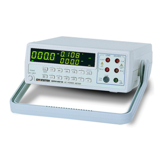
POWER METER POWER METER USER MANUAL USER MANUAL 2. INTRODUCTION 3. SPECIFICATION VOLTAGE GPM-8212 Power Meter is a 16-bit CPU microprocessor equipped with 5.000V, 10.00V, 20.00V, 40.00V, 80.00V, 160.0V, 320.0V, Range multifunction of full-digitized measurement, calibration and output. The 640.0V total 8 ranges by auto-range or manual. Measurement Type True rms microprocessor has the advantage of high-speed sampling and calculation... - Page 6 POWER METER POWER METER USER MANUAL USER MANUAL 4. PANEL AND OUTLOOK INTRODUCTION POWER FACTOR Range 0.001 to 1.000 Fig 4.1 FRONT PANEL W ÷ (V × A) = Power factor (PF) Computation FREQUENCY Measurement Range 40.0Hz to 400.0Hz ±0.2% of reading±2 digits Accuracy (23℃±5℃) OPTION Communication...
- Page 7 POWER METER POWER METER USER MANUAL USER MANUAL (5) Unit Indicator 4-1.Function Description Display Window 【1】Milliwatt indicator. (1) Remote Control Indicator Remote Control Indicator Display Window 【1】Watt indicator. (3) Status Indicator Display Window 【1】Kilowatt indicator. When the instrument is working normal, the RUN indicator is flashing stably, if not, it will be appeared constant on or off.
- Page 8 POWER METER POWER METER USER MANUAL USER MANUAL (8) Pushbuttons Display Window 【3】Kiloampere indicator. Set up address for RS-458 interface only. LOCAL ADDR ․ Number key. Display Window 【 2 】 Auto-range indicator. The Auto indicator is on when the window of voltage Set interface baudrate with 1200, 2400, 4800 and BAUD measurement is set to auto-range.
- Page 9 POWER METER POWER METER USER MANUAL USER MANUAL Number key. Fig. 4-2 REAR PANEL Set the voltage range downward, press and hold the V▽ RS-232/RS-485 button for 2 seconds to enter autorange of voltage. Current Breaker Interface Output Power Inlet Number key.
-
Page 10: Usage Description
POWER METER POWER METER USER MANUAL USER MANUAL 4-2.Wiring 5. USAGE DESCRIPTION Without PT or CT: Baudrate setting 1) Press the button of Baud to appear the letter of BAUD on the window 2, window 3 indicates the previous setting parameters, and window 1 appears "————". -
Page 11: Rs232 Communication Interface
POWER METER POWER METER USER MANUAL USER MANUAL 6. RS232 COMMUNICATION INTERFACE PT Ratio setting 1) Press the button of [VPT] to appear the letters of PT on the window 2, Introduction window 3 indicates the previous setting parameter, and window 1 The instrument can be operated from a host (eg. - Page 12 POWER METER POWER METER USER MANUAL USER MANUAL Communication command DEMO Program COMMAND DESCRIPTION EXAMPLE ; Demo program language: BASIC Data hold enable ; Computer set Baudrate equal 9600, and use COM2 Data hold disable ; The GPM-8212 set Baudrate equal 9600 Set in maximum status ;...
-
Page 13: Maintenance
POWER METER POWER METER USER MANUAL USER MANUAL 7. MAINTENANCE 7-2.Fuse Replacement Procedure The following instructions are used by qualified person only to avoid When you proceed calibration or maintenance of the Power Meter, if you electrical shock, do not perform any service other than contained in the want to replace the fuse, the upper cover must be removed according to the operation instructions unless you are qualified to do so. - Page 14 POWER METER POWER METER USER MANUAL USER MANUAL 2).Pull apart the handle from the Power Meter. Please turn the handle left and 4).Please use a screwdriver to open the screw located at upper side of rear panel. right side slightly, that will make it easier to pull off the handle. Therefore, the upper cover can pull toward the backside.
Need help?
Do you have a question about the 82PM-82120MB and is the answer not in the manual?
Questions and answers