
Subscribe to Our Youtube Channel
Related Manuals for GW Instek GSM-20H10


Summary of Contents for GW Instek GSM-20H10
- Page 1 Programmable High Precision DC Source Meter GSM-20H10 User Manual GW INSTEK PART NO. 82SM320H10E01 ISO-9001 CERTIFIED MANUFACTURER...
- Page 2 Copyright Statement This manual contains proprietary information, which is protected by copyright. All rights are reserved. No part of this manual may be photocopied, reproduced or translated to another language without prior written consent of Good Will company. The information in this manual was correct at the time of printing. However, Good Will continues to improve products and reserves the rights to change specification, equipment, and maintenance procedures at any time without notice.
-
Page 3: Table Of Contents
GSM-20H10 User Manual Table of Contents SAFETY INSTRUCTIONS..........5 Safety Notes ............5 Symbols ..............6 Guidelines .............. 8 Power Cord For The United Kingdom ....10 OVERVIEW ..............12 Main Function ............. 12 Overview ..................12 Main Function ................13 Key Features .................. - Page 4 Table of Contents Preparation ............41 Operating Environment ............... 41 Funtion Overview ................. 42 Parameter Setting Method ............44 Source Function ........... 46 Circuit Configuration ..............46 V/I Output Range ................. 48 Sink Function ................. 53 Operation Precautions ..............54 Front Panel Programming Interface ...........
- Page 5 GSM-20H10 User Manual Range Limitation ..........145 System Parameters ..........148 Save/Recall ............156 Factory Settings ..........157 Software Upgrade..........162 System Clock ............. 165 Mobile Disk Usage ..........166 REMOTE CONTROL ..........167 Setting Interface ..........167 USB ....................167 RS-232 .....................
- Page 6 Table of Contents Measurement Commands ............286 Status Commands ................. 312 System Commands ............... 317 Trigger Commands ............... 328 IEEE488.2 Common Command ........... 344 Status Registers ..........348 The Structure Of Status Registers ..........349 Programming And Reading Registers ........350 Status Byte And Service Request (SRQ) ........
-
Page 7: Safety Instructions
GSM-20H10 User Manual AFETY INSTRUCTIONS This chapter contains important safety instructions that you must follow during operation and storage. Read the following before any operation to insure your safety and to keep the instrument in the best possible condition. Safety Notes... -
Page 8: Symbols
ATTENTION instrument. Always read the associated information very carefully before performing the indicated procedure. Ensure conditions or practices suit instrument in CAUTION case damage to the GSM-20H10 or to other properties. Such damage may invalidate the warranty. - Page 9 GSM-20H10 User Manual Ensure conditions or practices suit instrument in WARING case injury or death. If the symbol is marked on the instrument, it DANGER means that the instrument can supply or measure a voltage of 1000V or more, including the common influence of normal voltage and common mode voltage.
-
Page 10: Guidelines
Do not discharge static electricity to the unit. Do not block the cooling fan opening. Do not disassemble the GSM-20H10 unless you are qualified. EN 61010-1:2010 specifies the measurement categories and their requirements as follows. - Page 11 GSM-20H10 User Manual Pollution degree 2: Normally only non-conductive pollution occurs. Occasionally, however, a temporary conductivity caused by condensation must be expected. Pollution degree 3: Conductive pollution occurs, or dry, non-conductive pollution occurs which becomes conductive due to condensation which is expected. In...
-
Page 12: Power Cord For The United Kingdom
SAFETY INSTRUCTIONS Do not use chemicals containing harsh products such as benzene, toluene, xylene, and acetone. Operation Location: Indoor, no direct sunlight, dust free, Environment almost non-conductive pollution (Note below) Relative Humidity: < 80% Altitude: < 2000m ... - Page 13 GSM-20H10 User Manual to the Earth terminal marked with either the letter E, the earth symbol or coloured Green/Green & Yellow. The wire which is coloured Blue must be connected to the · terminal which is marked with the letter N or coloured Blue or Black.
-
Page 14: Overview
OVERVIEW VERVIEW This chapter contains a brief introduction to GSM- 20H10, including the main features, as well as an overview of the front and rear panel. Use the Getting Started chapter on page 30 to start up instructions and how to setup the appropriate operation environment. Main Function Overview The GSM combines a precise, low-noise, highly stable DC power... -
Page 15: Main Function
GSM-20H10 User Manual Main Function Four Quadrant Source Function (V/I) GSM-20H10, as a conventional power supply, has the function of automatic CC/CV crossover function. You can use the front panel to set as voltage source or current source, and configure parameters such as voltage testing, current testing, display digits, data sampling period, power status, OVP, etc. - Page 16 GSM and other instruments (via the Trigger Link). For details, see page 136. Remote Control To meet the various needs of customers, the GSM-20H10 is designed for USB (TMC), RS-232, GPIB and LAN remote control. For details, see page 167.
-
Page 17: Key Features
GSM-20H10 User Manual Key Features General Low noise, the speed of fan is controlled by thermostatic. Compact, meets the 2U height and 1/2Rack width requirement. 4.3 inch TFT LCD display. Constant voltage and constant current operation ... - Page 18 OVERVIEW Reading and setup storage, up to 2500 readings ˙ and six storage area (four user settings, two factory defaults) can be stored and recalled. Protection Overvoltage protection (OVP). ˙ Overtemperature protection (OTP). ˙ Interface USB remote control. ˙ RS-232 remote control. ˙...
-
Page 19: Front Panel
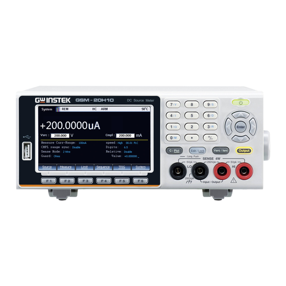
GSM-20H10 User Manual Front Panel LCD Display Numberpad and Power Secondary function key on/off button USB host port Auxiliary Funtion key Front panel Input/ function key Output terminals Display & Parameter Power on Display (Source) - Page 20 OVERVIEW Description The display is used primarily to program source and compliance values and display the real measured readings, The area is divided as follows. ① Status and Error messages Status and error messages are displayed momentarily, which are located on the top of the display, indicate various states of operation.
- Page 21 GSM-20H10 User Manual When measuring I: ˙ 3 integer digits for 100mA or 100uA range ˙ 2 integer digits for 10mA or 10uA range ˙ 1 integer digits for 1A or 1mA or 1uA range When measuring Ω ˙ 3 integer digits for 200MΩor 200kΩ or 200Ω...
- Page 22 OVERVIEW Voltage source/Current source setting operation: Contains 3 aspects, as shown in the figure: a, Vsrc or Isrc setting, the Vsrc/Isrc button on the operation panel can be selected in turn. b, To set the Vsrc or Isrc range, using the Edit/Lock button on the operation panel can alternately select the src, Cmpl or parameter area.
- Page 23 GSM-20H10 User Manual Depending on which value is lower, the output will be clamped in the compliance setting (Actual compliance) or at the maximum of a fixed measurement range (range compliance). This feature effectively limits the power transmitted to the device. When the GSM is used as a current source, the voltage is clamped at the compliance value;...
- Page 24 OVERVIEW Maximum compliance value The following table summarizes the maximum compliance values of the measuring range: Measure range Max. Cmpl value 200mV ±210mV ±2.1V Voltage ±21V 200V ±210V ±1.05uA 10uA ±10.5uA Current 100uA ±105uA ±1.05mA 10mA ±10.5mA 100mA ±105mA ±1.05A The Cmpl setting of voltage or current contains three aspects, as shown in the figure: a,...
-
Page 25: Control Panel
GSM-20H10 User Manual ④ Set the parameter Under the middle horizontal line used for programming related parameters. Take the relevant settings of the voltage source as an example, as shown in the following figure: ⑤ Auxiliary function key The bottom line is function name of the keys F1 to F6. - Page 26 OVERVIEW Cancel/Har Short press C/Pict key to cancel dcopy key the chosen setting value. Long press (2 to 3sec) C/Pict key to copy current display interface. The screenshot will be stored to USB flash disk automatically. See page 166 for operation details. Voltage and Voltage-source (Vsrc)/ Current- Current...
- Page 27 GSM-20H10 User Manual Edit /Lock The instrument must be in the edit mode to set source and compliance values.The edit mode is selected by short pressing the Edit/Lock key. The editing cursor (marking digit) appears for the source or compliance edit. If a value is not edited within 6 seconds, the edit mode is cancelled.
- Page 28 OVERVIEW Number a, The number pad is used to enter various parameters values. b, V/ I/ Ω/M, measurement shortcut keys. These buttons can only operate in the case of non digital input .V/ I shortcut keys can operate in Source and Measure function, Ω/M shortcut keys only operate in Measure function.
-
Page 29: Terminals
GSM-20H10 User Manual Terminals Input/Outp The middle two terminals are the Input and Output of the source. Terminals (SOURCE) Voltage On both sides are voltage feedback Feedback terminals corresponding to Terminals positive and negative terminals. (SENSE) These two terminals are used for 4-... -
Page 30: Terminals
OVERVIEW Terminals AC power Power on or power off the switch main circuit, GSM-20H10 is in standby state after pressing I, and the standby light on the front panel is red. I->on, O->off AC input The AC input accepts 100 to socket and fuse 240±... - Page 31 GSM-20H10 User Manual Digital I/O There are 15 I/O ports: one port +5V output ports, one GND port, four digital output lines and four trigger link lines, two input signal lines, three idle lines. See Limit function on page 115 and Trigger function on page 143.
-
Page 32: Getting Started
Safety Remind During the power-up, voltage spikes may appear on the terminals of the GSM-20H10. These voltage spikes could be at hazardous levels (42.4V peak) and could damage sensitive DUTs. Never touch external circuitry or the test leads when powering up the GSM-20H10. -
Page 33: Prepare & Start Up
100-240VAC ±10%, 50Hz/60Hz .Check to be sure the operating voltage in your area is compatible. GSM-20H10 can automatically detect and display the power line frequency (if the wrong power line frequency is displayed, you can set it manually). CAUTION: Operating the instrument on an incorrect line voltage may cause damage, possibly voiding the warranty. -
Page 34: Turn The Power On
GETTING STARTED CAUTION: The power cord supplied with GSM-20H10 contains a separate ground for use with grounded outlets. When proper connections are made, instrument chassis is connected to power line ground through the ground wire in the power cord. Failure to use grounding may cause personal injury or death due to electric shock. -
Page 35: Turn The Power Off
GSM-20H10 User Manual Line frequency At the factory, the GSM is configured to sense the setting power line frequency and display. If the line power source is noisy, the GSM may select the wrong setting on power-up. If this situation occurs, noisy measurement readings will result, and accuracy may be affected. -
Page 36: Connect To Load
(rear panel). WARNING: To prevent electric shock and damages to the GSM-20H10, DO NOT exceed the maximum allowable voltage differentials shown in terminals. The front and rear terminals of the GSM are rated for connection to circuits rated Installation Category I only. -
Page 37: Sense Connect Methods
GSM-20H10 User Manual Sense Connect Methods Description Basic source-measure operations are performed using either 2-wire local sense connections or 4-wire remote sense connections. The factory default sense selection is local. Note: The front panel terminals are isolated from the rear panel terminals. Therefore, if you are using the front panel terminals, ground the front panel LO terminal. - Page 38 GETTING STARTED 4-wire When measuring the voltage, there may be a remote deviation caused by the line resistor of the leads. sensing Using 4-wire connection can optimize the measurement accuracy and ensure that the programmed voltage is transmitted to the DUT. When measuring the voltage, only the voltage drop on the DUT is measured.
-
Page 39: Sense And Guard Selections
GSM-20H10 User Manual 2-wire local 2-wire local sense connections can only be used if the sensing deviation contributed by test lead IR drop is acceptable to the user. When current levels below 100mA, the errors are usually not significant (assuming test lead resistor is not greater than 1Ω). - Page 40 GETTING STARTED Front panel On power-up, the instrument is automatically set for 2- sense wire local sense. Perform the following steps to change selection the sense selection: 1. Click the Edit/Lock button and the direction keys to make the cursor stop in the Sense mode setting box. 2.
-
Page 41: Wires Selections
GSM-20H10 User Manual Wires Selections Recommended GTL-108A It can be used on the terminals of Cables source, sense and guard GTL-207A Used to measure external voltage and current Front and Rear Insert the selected wiring according to the print panel wiring... -
Page 42: Power On Settings
GETTING STARTED Power On Settings Turn on/off Long press the standby power switch for at standby power least 2 seconds, and the standby light turns yellow Long press the standby power switch for at least 2 seconds, and the standby light turns red Automatic output Any of the following actions will cause the output to be automatically off:... -
Page 43: Basic Operation
Preparation Operating Environment Description The GSM-20H10 use a cooling fan to keep it from overheating, the speed of the fan is controlled by the temperature of the heat sink. When the Output is turned off, the fan will usually run at the low speed. -
Page 44: Funtion Overview
Adding a partition below it will help ensure adequate airflow. Funtion Overview Description From the front panel, the GSM-20H10 can be configured to perform the following operations: Source Funtion: • Source voltage — Display current or voltage measurement reading •... - Page 45 GSM-20H10 User Manual Source- The following table lists the source and measure Measure limits for the voltage and current functions. limitations Range Source Measure 200mV ±210mV ±211mV ±2.1V ±2.11V ±21V ±21.1V 200V ±210V ±211V ±1.05uA ±1.055uA 10uA ±10.5uA ±10.55uA 100uA ±105uA...
-
Page 46: Parameter Setting Method
BASIC OPERATION based on the range. Range Max.Cmpl.value 200mV ±210mV ±2.1V ±21V 200V ±210V ±1.05uA 10uA ±10.5uA 100uA ±105uA ±1.05mA 10mA ±10.5mA 100mA ±105mA ±1.05A Parameter Setting Method Description There are roughly the following types of GSM parameters, and the operations are as follows: Value Require to select the range, press Enter to make input... - Page 47 GSM-20H10 User Manual black), then use the above two numerical input methods to operate. Select There are up and down arrows in the edit box, use input the up and down arrow keys to select, and use the Enter key to confirm, as shown in the figure:...
-
Page 48: Source Function
BASIC OPERATION Source Function Circuit Configuration The basic source-measurement configuration of GSM-20H10 is shown in the figure. Under the voltage source or current source, you can measure current or voltage. voltage source current source Source V When configured as a V-Source, it operates as a low-... - Page 49 GSM-20H10 User Manual eliminates the effects of voltage drops in the test leads, ensuring accurate programming voltages on the DUT Source I When configured as an I-Source, the GSM operates as a high-impedance current source with voltage limiting capability and can measure current (as an ammeter) or voltage (as a voltmeter).
-
Page 50: V/I Output Range
BASIC OPERATION NOTE: The current source does not require or use Sense leads to improve the accuracy of the current source. When selecting 4-wire sensing, the sensing leads must be connected, otherwise it will cause incorrect results. Please refer to page 35 for the connection method. - Page 51 GSM-20H10 User Manual 1A, 20V and 100mA, 200V amplitude is the nominal value. The actual maximum output voltage and output current amplitude are 1.05A, 21V and 105mA, 210V. The limit in the image above is not a range. Operating I-Source operating boundaries: as shown in Figure 1...
- Page 52 BASIC OPERATION the area or on the restricted line. The limits of the four quadrants are similar. Voltage compliance boundary of I-Source: The operating points of the GSM within the boundaries depends on the load. The figures below shows the operating status when 200Ω and 800Ω resistive loads are connected respectively.
- Page 53 GSM-20H10 User Manual Figure 1 Figure 2 Figure 2 shows the limit boundaries of the V-Source, which characterizes the maximum source value of presently selected voltage source range. For example, for 20V source range, the limit line of the voltage source is 21V.
- Page 54 BASIC OPERATION When the load resistor increases, the slope of the load line decreases. When the resistor increases to infinity (open circuit), the actual output voltage of the GSM is 50V and the output current is 0mA. When the load resistance decreases, the slope of the load line increases.
-
Page 55: Sink Function
GSM-20H10 User Manual The measurement accuracy of the GSM is higher than the programming accuracy. Therefore, select the same programming and measurement functions and replace the programming accuracy with the measurement accuracy to obtain the best accuracy. Sink Function Description When the GSM is used as a sink (V and I have opposite polarities), it consumes energy. -
Page 56: Operation Precautions
BASIC OPERATION positive electrode of the battery), set the Vsrc of the GSM to -12V, and set the value of Cmpl to make the GSM operate in CC mode. At this time, the GSM operates at IV Quadrant. For example, connect the GSM to a -14V power supply (Input/Output HI is connected to the positive electrode of the battery), set the Vsrc of the GSM to -12V, and set the value of Cmpl to make the... -
Page 57: Front Panel Programming Interface
GSM-20H10 User Manual WARNING: To prevent damage to the DUT (device under test) or external circuits, do not program the voltage source to a level that exceeds the voltage protection limit. Be careful when the GSM floats >30V rms Source... -
Page 58: Parameter Description And Operation
BASIC OPERATION keys, and press the Enter key to confirm parameter setting. For numerical setting items, after selecting and Entering, if the pull-up and drop-down arrows appear, it means that there are multiple range options. Use the up and down keys to select the corresponding range, then enter the required value, and press Enter to confirm to complete the parameter setting. - Page 59 GSM-20H10 User Manual maximum signal that can be measured. When the output is off, a dotted line (such as ---. ---- μA) will be displayed to indicate that the measurement is not performed. Range setting When in the editing state, operate the up and down direction keys to confirm the required range with the decimal point and unit.
- Page 60 BASIC OPERATION the left and right direction keys to select the digit to be fine-tuned, and press the up and down direction keys to increase or decrease the value. After setting, press Enter to confirm. NOTE: The time limit for editing is about 6 seconds.
- Page 61 GSM-20H10 User Manual 1mA range: 1.000000mA 10mA range: 10.00000mA 100mA range: 100.0000mA 1A range: 1.000000A Numerical input Numerical key input: Use the Numerical keys 0~9 to input the required value in digits order, and press Enter key to confirm. Digit-by-digit input: After inputting the first...
- Page 62 BASIC OPERATION four ranges 200V, 20V, 20V, 200mV. Manual range: For Source V/Measure I, Source I/Measure V and Ohms measurement configurations, a fixed range can be selected. Please note that the highest available range depends on the corresponding compliance value. If inputing power exceeds compliance range(include "real value"...
- Page 63 GSM-20H10 User Manual range based on the current reading. If the reading is 10% of the current range, the instrument will drop one range; if the reading is 1% of the current range, the instrument will drop two ranges; if the reading is 0.1% of the current range, the instrument will...
- Page 64 BASIC OPERATION use the up and down keys to select the required range, press Enter to confirm and exit the editing state. Sync Setting measurement reading range to synchronize cmpl with compliance range, the default setting is Disable range when power-on. To enable Sync cmpl range, Auto for Measure volt-range or Measure curr-range should be deselected, that is, turn off the Auto range function.
- Page 65 GSM-20H10 User Manual WARNING: When the V-Source is programmed to 4-wire sense mode, you must ensure that Sense HI and Sense LO terminals are connected to both ends of the DUT respectively. If one terminal is not connected, the voltage detected on Sense port is 0V, and the GSM will compensate by increasing the output voltage.
- Page 66 BASIC OPERATION Cable guard: Used in the case where the impedance of the circuit under test is greater than 1GΩ, using the high-impedance guard connection. It is usually necessary to use shielded wires and test fixtures to test high-impedance equipment, which can reduce interference and protect the users from being injured by hazardous voltage on the guard shield (or plate).
- Page 67 GSM-20H10 User Manual mode. The V.Ω GUARD is connected to the metal plate equipped with insulated measuring column through test lead. Since the voltage at both ends of the insulation measuring column equal, the voltage drop on its parasitic resistor (RL1 and RL2) is 0, and no leakage current passes.
- Page 68 BASIC OPERATION Ohms guard: Provide low internal resistor (<1Ω), high output current (up to 50mA) drive protection, allowing resistor measurement in the circuit. When measuring the resistor component in the resistor network, eliminate the influence of the resistor in parallel with it. Guarded ohms measurement mode is divided into three connection methods according to the impedance of the DUT:...
- Page 69 GSM-20H10 User Manual respectively to the voltage drop on the Rg, causing the potential at the connection between R1 and the V.Ω GUARD terminal to be lower than the potential at the connection between R1 and the Input/Output HI terminal. Furthermore, there is leakage current flowing through R1 which will affects the measurement accuracy.
- Page 70 BASIC OPERATION states for Off state option. NOTE: Ohms guard cannot be selected in 1A range (as source or meter). If you have selected Ohms guard, you cannot select 1A range. The Guard terminal current cannot exceed 50mA, otherwise the Guard terminal voltage will be less than the Input/Output terminal voltage and affect the measurement data.
- Page 71 GSM-20H10 User Manual Generally speaking, the fastest sampling speed (Fast: 0.01PLC) will result in an increase in reading noise and a decrease in the number of available digits. The slowest sampling speed (High: 10PLC) provides the best accuracy and noise suppression. The middle settings are compromise between speed and noise.
- Page 72 BASIC OPERATION Digits synchronously, but changing the Digits does not affect the Speed setting. Digits The display digits of the measurement reading. There is four options of 3.5, 4.5, 5.5, and 6.5. This setting is global. After setting the display digits, it is valid for the display reading of all measurement functions (voltage, current, resistance).
- Page 73 GSM-20H10 User Manual time, it is CC mode, Relative option selects Enable, and Value is set to 1V, press the Output button, at this time, the displayed value is the difference between the output voltage value loaded on the load and the Relative Value.
- Page 74 BASIC OPERATION NOTE: Relative Value is valid to all the ranges. For example, if the Relative Value is set to 5V in the 20V range, when the range is changed to 2V or 200V, the Relative Value is still 5V. When the programmed Relative Value exceeds the slected range, it will not cause overflow and will not increase the maximum allowable input...
- Page 75 GSM-20H10 User Manual Press the up and down arrow keys to move the cursor to the OVP state option box and press the Enter key to select Enable or Disable. When you select Enable, the OVP function is enabled, and the OVP symbol is displayed in the status bar.
- Page 76 BASIC OPERATION The delay of the SDM cycle can make the source stabilize before the measurement. The source delay can be manually set from 0000.00000 seconds to 9999.9990 seconds using Delay setting box; if the Auto delay is Enabled, the delay time depends on the presently selected source range.
- Page 77 GSM-20H10 User Manual determined by the selected measurement range. When Disable is selected, enter a custom time in the Delay box. Current Range 1uA 10uA 100uA 1mA 10mA 100mA Auto dalay (V )3ms 2ms 1ms 1ms 1ms Auto dalay (I...
- Page 78 BASIC OPERATION second sequence point, Vsrc becomes 12V by the first sweeping point V value 1.2V multiplying the Scale factor (10). After sweeping the third sequence point, Vsrc becomes 1.2V by the second sweeping point V value 12Vmultiplying the Scale factor (0.1). The output voltage after trig control are shown in the figures below:...
- Page 79 GSM-20H10 User Manual Isrc trig Used to control the current source trigger, move the control cursor to the Isrc trig control box, press Enter and the Arrow keys to select Enable or Disable, when selecting Enter, input the value in the Scale factor box.
-
Page 80: Output Operation
BASIC OPERATION Output Operation Step Generally have the following: Connect the external connection (front-panel or rear-panel) according to the requires of the test. For rear-panel output, enter System->Control->Rear in turn. Set Vsrc or Isrc and Cmpl on the front panel. Set other parameters in the parameter area (Measure interface). - Page 81 GSM-20H10 User Manual When the GSM is set as V-Source, in case that the terminal output current is not restricted by Cmpl or Measure cur-range, the GSM operates in CV (constant voltage) mode When the GSM is set as V-Source, in case that the...
-
Page 82: Measure Function
BASIC OPERATION Measure Function In addition to being used as a source, the GSM can also be used as meter with the Measurement function, which can directly measure voltage, current, and resistor, and can also do some calculation measurements. Measurement Interface Display The Measure interface is basically the same as the Source (only increase setting items for resistor... -
Page 83: V/I Meter
GSM-20H10 User Manual Measure. There are two ways of front and rear output (when REAR markis displayed in the status bar, it means the output is from the rear panel, otherwise the output is from the front panel). The front and rear panels cannot output at the same time. - Page 84 BASIC OPERATION WARNING: When the GSM is used as a voltmeter, Cmpl must be set to be higher than the voltage that is being measured. If this setting is not done, excessive current will flow into the GSM and cause damage. Set range When setting Measure volt-range or Measure curr- range, select a range suitable for the voltage or current...
-
Page 85: Ohms Meter
GSM-20H10 User Manual Ohms Meter Measurement Press the F2 (Measure) key, and then press the interface "1/Ω" key to enter the resistor measurement interface. Description Use I to set the source value when measuring resistor. When the Ohms source is selected to Auto, the GSM is defaulted as I-Source and operates as a traditional I-Source ohmmeter. - Page 86 BASIC OPERATION 2V to a 2kΩ resistor, the lowest allowable current compliance is 1mA (2V/2kΩ = 1mA). Setting a Cmpl value lower than 1mA will place the source in compliance. Using 4-wire sense mode to measure resistor can obtain higher measurement accuracy than 2-wire sense mode.
-
Page 87: Calculation
GSM-20H10 User Manual Calculation Description Long press the F2 (Measure) key, enter the interface for calculation operation, including five function menus: Power, CompOhms, Vceoff, VarAlpha, and DEV. The Power and DEV functions perform single-point measurements to obtain results. CompOhms, Vceoff and VarAlpha functions require... - Page 88 BASIC OPERATION CompOhms: Ohm compensation function. The existence of thermoelectric potential affects the measurement accuracy of low value resistor, CompOhms function can be used to reduce the influence of offset voltage. Calculated as follows: CompOhms Ω=(V2-V1)/(I2-I1) V1 represents the voltage measurement reading measured by the first programmed I-Source value, V2 represents the voltage measurement reading measured by the second programmed I-Source value,...
-
Page 89: Parameter Description And Operation
GSM-20H10 User Manual reading measured by the first programmed source value, and V2 represents the voltage measurement reading measured by the second programmed source value. When calculating the Vceoff value, two voltage source values need to be set. VarAlpha: The alpha (α) value defines the characteristics of the varistor. - Page 90 BASIC OPERATION Measure – *The detailed setting operations are the same as the range/ Sync Source chapter decription, please refer to page 56. cmpl rang/ Sense mode/ Speed/Digits/ *Press “9/S”, “6/D” and “3/R” to quickly operate Relative to set Speed/ Digits/ Relative option When it comes to resistance measurement, the following parameters require to be programmed as: Measure...
- Page 91 GSM-20H10 User Manual Ohms source This option is used to select manual or auto measurement mode when measuring resistance. When selecting Auto, the GSM operates as a traditional I-Source ohmmeter. When the manual mode is selected, the GSM can be switched to V- Source or I-Source.
- Page 92 BASIC OPERATION into a red letter with a gray background), and press Enter. When the up and down arrow signs appear, operate the up and down direction buttons to select the required option (Enable or Disable), and then press Enter to confirm. Readback When Readback option selects Enable, the measurement reading are the actual output voltage...
-
Page 93: Parameter Settings Of Calculation Function
GSM-20H10 User Manual Parameter Settings Of Calculation Function Power This calculation function uses the measurement voltage value multiplying the measurement current value to obtain the Power measurement reading, and the unit of the displayed value is watts. Operation steps: Press the F2 (Measure) key to enter the Measure... - Page 94 BASIC OPERATION CompOhms Compensation function for resistance measurement. Operation steps: Press the F2 (CompOhms) key, select CompOhms (the font turns red), and the cursor will automatically jump to the CompOhms (Vs/Is) item. Operate the Enter key, the arrow keys and the number keys to set the values of I1 and I2 in sequence.
- Page 95 GSM-20H10 User Manual Vceoff Used to measure the voltage coefficient of high value or megohm resistor. Operation steps: Press the F3 (Vceoff) key, select Vceoff (the font turns red), and the cursor will automatically jump to the Vceoff item. Operate the Enter key, the arrow keys and the number keys to set the values of V1 and V2 in sequence.
- Page 96 BASIC OPERATION NOTE: When programming the value of V1 and V2, the up and down direction keys can switch the voltage range, and the value should be set in the most suitable range according to the range of the resistor to be measured. For example, when the GSM is connected to a 2MΩ...
- Page 97 GSM-20H10 User Manual Press the 0/M key to switch to the calculation Measure interface. The VarAlpha symbol appears in the display area, indicating that the VarAlpha to be calculated. Finally, turn on the Output key, and the measurment reading of VarAlpha will be displayed.
- Page 98 BASIC OPERATION Operation steps: Press the F5 (DEV) key, select DEV (the font turns red), and the cursor will automatically jump to the DEV item. Operate the Enter key, the arrow keys and the number keys to set the Ref value and also HI tol value and LO tol value in sequence.
-
Page 99: Measurement Operations
GSM-20H10 User Manual Measurement Operations Steps Generally there are the following steps: Connect the external test leads (front-panel or rear-panel) according to the requires of the test For rear-panel output, set it according to System->Control->Rear. Set Vsrc or Isrc and Cmpl on the front panel... - Page 100 BASIC OPERATION When the GSM is set as I-Source, in case that the terminal output voltage is restricted by Cmpl or Measure vol- range, the GSM operates in CV (constant voltage) mode When the GSM is set as V-Source, in case that the terminal output current is not restricted by Cmpl or Measure cur- range, the GSM operates in CV (constant voltage) mode When the GSM is set as V-Source, in case that the terminal...
-
Page 101: Limit Function
GSM-20H10 User Manual Limit Function Display Interface Description Limit test classification: There are three types of limits: compliance value (Cmpl), coarse limit (Limit 2), fine limit (limit 3, 5-12). When Output is ON, pressing the F3 (Limit) key will trigger the operation of the limit function as long as the... - Page 102 BASIC OPERATION Limit 1 test (compliance): It is a hardware test, which checks the compliance status of the GSM, and uses the programmed compliance value as the test limit.If the measurement reading is at or above the programmed compliance value, indecating that the GSM is in compliance.
-
Page 103: Parameter Description And Operation
GSM-20H10 User Manual Parameter Description And Operation Setting Long press F3(Limit) button to enter the setting interface interface as shown in the figure below: There are 5 sub-menus to be programmed respectively: F1(Digout) F2(HW-Limits) F3(SW-Limits) F4(Pass) F5(EOT-Mode) Digout Size Used to control the bits number of digital I/0. Choose 3 or 4 or 16 digits. - Page 104 BASIC OPERATION When the Size is 4-bit, the range of the pattern value is 0-15. When the Size is 16-bit, the range of the pattern value is 0-65535. Setting: Move the cursor to the item to be programmed (it turns into a red letter on a gray background), and press Enter.
- Page 105 GSM-20H10 User Manual key, and then press the F3 (Limit) key. Because the measurement reading conforms to HW-Limits and SW-Limits , the interface displays the limit test result PASS, and the I/O port outputs a Pass pattern value of 5 (Line3-Line1 of the Digital lines corresponds to...
- Page 106 BASIC OPERATION When Grading is set to End, regardless of whether a failure occurs, the test process will proceed to the completion of the software operation. This function can be used to test multiple devices. After the measurement is completed, the bit pattern value after the first failure is output.
- Page 107 GSM-20H10 User Manual The operating flow of Grading mode is shown in the figure below:...
- Page 108 BASIC OPERATION...
- Page 109 GSM-20H10 User Manual SORTING mode: If a measurement reading fails the Compliance Test, or is not within any SW-Limits range, the Limit test will display FAIL. If the measurement reading passes the Compliance Test and only Limit 1 is enabled, the corresponding Pass pattern value will be output.
- Page 110 BASIC OPERATION...
- Page 111 GSM-20H10 User Manual Setting: Move the cursor to the item to be changed (it becomes a red letter on a gray background), press Enter, and when the up and down arrow signs appear, operate the up and down direction buttons to select the appropriate method (Immediate or End), and then press Enter to confirm.
- Page 112 BASIC OPERATION Setting: Move the cursor to the item to be changed (it turns into a red letter on a gray background), press Enter, and when the up and down arrow signs appear, operate the up and down direction keys to select the required option (Enable or Disable), and then press Enter to confirm.
- Page 113 GSM-20H10 User Manual Operate the direction keys or numeric keys to input the desired value. SW-Limits Press the F3 (SW-Limits) key to control the enabling of LIM2, LIM3, LIM5-LIM12, High/Low limit range and fail pattern value. The specific settings are shown in the figure below:...
- Page 114 BASIC OPERATION numeric keys to input the required value. Lo_fail Setting the low fail pattern value of LIM2, LIM3, LIM5 -LIM12. When Digout size is 3 bits, the value is 0 to 7, and when Digout size is 4 bits, the value is 0 to 15.
- Page 115 GSM-20H10 User Manual Press the F4 (Pass) key for the related actions under PASS. Related instructions can refer to page 123. Pass pattern Used to define the digital output bit value. When the Digout size is 3 digits, the value digits are 0-7, and when the Digout size is 4 digits, the value digits are 0- 15.
- Page 116 BASIC OPERATION background), press Enter, and it is in the programming state. Operating the direction keys or numeric keys to input the desired value. EOT-Mode End of test Define the 4th line of Digital I/O lines as EOT signal mode or Busy signal.
-
Page 117: External I/O
GSM-20H10 User Manual External I/O Description The GSM can be connected to an external device through the external DIGITAL I/O port. The DIGITAL I/O port includes 4 output lines and 2 input lines. line5:+3.3V Definition line7:GND line6,8:IDLE line9: +5V output, used to drive external logic circuits. - Page 118 BASIC OPERATION Source operation: Connect an external relay between one of digital output lines and the GND wire. The digital output line must be set to high level to drive the relay. The maximum source current is 2mA. The connection method is shown in the figure below: Sink current operation: connect an external relay between one of digital output lines and the +5V power supply.
-
Page 119: Limit Operation
GSM-20H10 User Manual As shown in the figure below, when the output enable function is enabled , the output enable line is pulled down if the switch to ground is closed, then the Output of the GSM is turned on. If the lid of the... - Page 120 BASIC OPERATION according to test requirements. Set source-measure related parameters. Select and set the relevant parameters of Limit test. Select the required measurement reading type V/I/Ω/M (corresponding to the buttons 7/V, 3/I, 1/Ω, 0/M). Press the Output key to turn on the output, and the GSM will output the programmed voltage.
-
Page 121: State Description
GSM-20H10 User Manual State Description REAR Display when setting as rear-panel output. Otherwise, it is the front-panel output Remote control When the GSM is set as I-Source, in case that the terminal output voltage is restricted by Cmpl or Measure vol-... -
Page 122: Sequence Function
BASIC OPERATION Sequence Function Display Interface Description This function can be used when different voltage and current waveforms need to be output in practical applications. Users can program the output waveform according to needs. The amplitude range of the output waveform is the range of output voltage or current of the GSM. -
Page 123: Features
GSM-20H10 User Manual Features There are four types of Sequence: Stair, Log, Custom, and SRC-MEM. Stair The output of the waveform depends on the following parameters: Start value, Stop value, Step (Stair) value, Delay value (Determined by Source delay, trigger delay and Speed which can be set separately). - Page 124 BASIC OPERATION The output of the waveform depends on the following parameters: Start value, Stop value, Points (log) number, Delay time (Determined by Source delay, trigger delay and Speed which can be set separately). As shown below: When starting sequence, the output will go from the bias level to the Start piont, and run to the Stop point in equal logarithmic steps.
- Page 125 GSM-20H10 User Manual SRC- Source memory sequence type. For this sequence type, setup configurations of 100 points can be stored in the memory. When starting sequence, the setup at each memory point can be recalled, allowing multiple functions and math expressions to be used in a sequence.
- Page 126 BASIC OPERATION location 8 when a PASS condition occurs at location 3. Be careful when branching, because you may unintentionally create an infinite memory loop. No matter how many branchs are performed, the point number of the TRIG count SRC-MEM sequence is the setting value of The SRC-MEM sequence branching can be set in the Source memory location and Location options in the PASS section of the Limit chapter.
-
Page 127: Parameter Description And Operation
GSM-20H10 User Manual Parameter Description And Operation Description There are 2 ways to enter the parameter setting interface of Sequence: Long press the F4 (Sequence) key. When Output is turned off, press the F4 key to enter the Sequence data browsing interface, and then press the F1 (Setting) key to enter. - Page 128 BASIC OPERATION Stop Set the stop point of the Stair/Log output waveform, Vsrc or Isrc depends on the source type of main interface. Operation: Use the derection keys to place the cursor on the Stop option (the numbers in the edit box turn into red on the gray background), press Enter button to enter the editing state, select the range with the up and down arrow keys, input the required value...
- Page 129 GSM-20H10 User Manual Move the cursor to the Memory save option box, press Enter, enter a number between 1-100, and press Enter, the following dialog box appears: Move the cursor to OK button and press Enter to store the settings of the present Source interface in the memory location indicated by the number in the Memory save box.
- Page 130 BASIC OPERATION Press Enter, enter a number between 1-100, press Enter, the following dialog box appears, move the cursor to OK button and press Enter, which means to recall the settings in the corresponding memory location indicated by the number in the Memory restore box to present Source interface.
- Page 131 GSM-20H10 User Manual The time parameters are determined by Source delay, trigger delay and Speed which can be set separately. As shown in the figure below, set the Number of points to 10. Press the F2 (Block) key to set the Start point to 0 and set the Stop point to 8, the Value is set to 10V.
- Page 132 BASIC OPERATION value and confirm. SRC-range Used to control the range of the source, you can choose Bestfixed, Fixed or Auto-range, the meaning of each option is as follows: Bestfixed: Means that a range suitable for all points in the sequence is automatically selected. Fixed: Means to keep the source remain on the range when the sequence is started.
- Page 133 GSM-20H10 User Manual Store time The time stamp for storing the first measurement stamp reading in the buffer (#0000) is marked as 0000000.000s. The buffer of GSM can store 2500 source-measure readings. Each source-measure reading is assigned a storage address and a time stamp.
-
Page 134: Generating Waveform And Exporting File
BASIC OPERATION Generating Waveform And Exporting File Description After a Sequence is completed running, turning Output off, click the F4 (Sequence) key to enter the review interface, and you can look back the running result in time. There are 3 ways: By changing the size of Location, you can review the measurement information of each source point one by one: V/I measurement reading, Absolute... - Page 135 GSM-20H10 User Manual Parameter description: Scale: Set the type of horizontal and vertical coordinates and the scale, as shown in the dialog window: There are 4 choices of Graph: I/V, V/I, V/t, I/t; Xmax, Xmin, Ymax, Ymin are the maximum or minimum coordinates value of the X and Y axes.
- Page 136 BASIC OPERATION Auto: Automatically generate curve for source-measurement readings (sequence points), I-V is the default curve. If you click the F3 (Data) key in the sequence output review interface, you can view the specific output value and export the waveform file (.CSV format, easy to browse on PC).
-
Page 137: Sequence Output
GSM-20H10 User Manual Sequence Output Operation Generally there are the following steps: Connect the external connection (front panel or rear panel) according to the requirement of the test. For rear panel output, set it by System->Control- >Rear. Set Vsrc or Isrc and Cmpl on the front panel. -
Page 138: Trig Fuction
BASIC OPERATION TRIG Fuction Programming Interface Description Long press the F5 (TRIG) button on the main interface to enter the TRIG function setting interface:... -
Page 139: Trigger Process
GSM-20H10 User Manual Trigger Process The trigger mode is composed of the ARM layer and TRIG layer. The process is shown in the figure below:... -
Page 140: Parameter Description And Operation
BASIC OPERATION Parameter Description And Operation ARM Layer Press the F1(Arm) button, setting the Arm layer of the TRIG mode, and set the options in the ARM in, ARM count and ARM out. ARM in Source Used to select the trigger source of the Arm layer. It can be set as Immidiate, GPIB, Timer, Manual, Tlink, Rising edge, Falling edge, Edge, the specific description is as follows:... - Page 141 GSM-20H10 User Manual F5 (TRIG) key once, the event detection will be triggered to run once. Tlink: When an input trigger is received through the Trigger Link input line, event detection occurs.When selecting Tlink, you can bypass the Arm Event Detector by selecting the Bypass option to ONCE.
- Page 142 BASIC OPERATION NOTE: The F5 (TRIG) key in the main interface has the highest priority. An event will be triggered as long as you press this key. ARM count Mode Two options of Finite and Infinite are available. Finite: Indicates that the number of the ARM count is a certain value.
- Page 143 GSM-20H10 User Manual TRIG in Source Select the trigger source of the Trigger layer, which can be set as Immediate or Trigger link. Immediate: Indicates that the event is triggered immediately. When this option is selected, source event detector, delayed event detector and measurement event detector will run immediately.
- Page 144 BASIC OPERATION an input source trigger. Off: Indicate that operation will not wait and it will continue to perform the subsequent operations. Events Enable (On) or disable (Off) trigger-in delay. delay On: Indicate that operation will wait at that event for an input delay trigger.
-
Page 145: Interface Requirements
GSM-20H10 User Manual NOTE: TRIG count and the number of sequence points should be the same, or TRIG count should be multiples of the number of sequence points. For example, when sequence points is set to 5, and the TRIG count is set to 10, the sequence will run twice. - Page 146 BASIC OPERATION trigger signal line, and line2 is the output trigger signal line. These input and output lines can be changed in the Arm and Trig setting interface. Instructions ˙ line1-line4 input trigger requirements The input trigger is used to trigger the event detector of the Arm layer or the Trigger layer of the...
-
Page 147: System Settings
GSM-20H10 User Manual YSTEM SETTINGS This chapter mainly includes system parameter settings and software upgrading, such as power-on status/IO port/output status/remote interface/system time and other settings. Range Limitation Click F6 (System) button on the main interface to enter the System setting interface. It has four submenus: Auto, Control, Interface, and Memory. - Page 148 SYSTEM SETTINGS phase of the SDM cycle to minimize the possibility that the GSM will be in compliance in a multiple GSM system. As long as the GSM taking a measurement reading, it will perform a downrange action. Soak time: Soak time needs to be set only when Auto range type is set as Multiple.
- Page 149 GSM-20H10 User Manual value. NOTE: For the three measurement functions of V, I and Ohms, if the programmed Llimit and Ulimit are equal, the Auto range function will be disabled accordingly and you can manually change to a range lower than Llimit(V, I or Ohms) or a range higher than Ulimit (Ohms only).
-
Page 150: System Parameters
SYSTEM SETTINGS System Parameters Control Line Set the power line frequency according to the frequence frequence of the power supply. It can be set as Auto, 50Hz or 60Hz. When setting to Auto, the GSM will detect the power line frequency and set it automatically when power on. - Page 151 GSM-20H10 User Manual Reset time Used to reset the time stamp when exiting the idle state. There are two options, Yes or No. stamp Yes: In the trigger mode, when exiting the idle mode, the time stamp is allowed to be reset automatically.
- Page 152 SYSTEM SETTINGS High impedance: In this Output-off state, when the Output is turned off, the output relay will open, disconnecting the Input/Output terminal from the external circuit. In order to prevent excessive loss of output relay, this output-ff state is not used for tests that require output off and on frequently.
- Page 153 GSM-20H10 User Manual When selected as I-Source: · The programmed I-Source value remains displayed. · Internally, select as V-Source and set the voltage to 0V. · The current compliance is set to the larger value of the programmed I-Source value and 0.5% full scale of the present measure...
- Page 154 SYSTEM SETTINGS When using the rear panel, connect the LO of the rear panel to the ground. The ground can be selected from the ground screw on the rear panel or other safety ground. Guard: In the Guard Output-off state, I-Source is selected and set the output current to 0A.
- Page 155 GSM-20H10 User Manual connect a spark discharge tube between INPUT HI and LO. Auto off: Used to Enable or Disable "output automatic off" function. Enable: Output will be turned off after the end of the measurement phase of each SDM cycle. Output will be turned on again at the beginning of the next SDM cycle.
- Page 156 SYSTEM SETTINGS the method how the filter handles the measurement readings with interference. There are two Average methods: Moving and Repeat: Moving: Use the first-in first-out method. When the stack is full, take the average of the measured value, which is the measurement reading in the display area.
- Page 157 GSM-20H10 User Manual average value of these values. The average value is actually the first measured value, which may not be the correct measurement reading. Therefore, it is not recommended to choose the Moving method. The programmed filter method is valid for all measurement functions.
-
Page 158: Save/Recall
SYSTEM SETTINGS Save/Recall Description There are 4 sets of system parameters available to users to program, named SAV0, SAV1, SAV2, SAV3. The system has 6 groups of setups that can be recalled which are Bench, GPIB, SAV0, SAV1, SAV2, SAV3 reapectively. Parameter The setups of each group have the following contents (taking the setups of Bench as an example):... -
Page 159: Factory Settings
GSM-20H10 User Manual page. Next Used to view the settings of the next page, page 11 items will jump every time you turn the page. Power on In the System setting interface, there is a Global settings power on option, which can define the power on settings. - Page 160 SYSTEM SETTINGS Filter: Disable Averaging type: Moving Count: GPIB address: No effect Limit tests: Digout: Size: 4bit Mode: Grading Binning control: Immediate Auto clear: Disable Delay: 0.00010s Clear Pattern: H/W Limit: Control: Disable Fail mode: Cmpl pattern: S/W limits: Lim 2: Control: Disable Low limit:...
- Page 161 GSM-20H10 User Manual Low limit: -1.000000 Low pattern: High limit: +1.000000 High pettern: Lim 8 Control: Disable Low limit: -1.000000 Low pattern: High limit: +1.000000 High pettern: Lim 9 Control: Disable Low limit: -1.000000 Low pattern: High limit: +1.000000 High pettern:...
- Page 162 SYSTEM SETTINGS Output enable: Disable Off Save_State Normal Auto-off Disable Power-on default: No effect Measure ohms range: 200M RS-232: No effect Source delay: 0.00030s Auto-delay: Enable Sweep: Stair Voltage start: +0.00000mV Voltage stop: +0.00000mV Voltage step: +0.00000mV Current start: +0.00000A Current stop: +0.00000A Current step:...
- Page 163 GSM-20H10 User Manual Name0: POWER Name1: OFFCOMPOHM Name2: VOLTCOEF Name3: VARALPHA Name4: Name5: User-Define Name6: User-Define Name7: User-Define Name8: User-Define Name9: User-Define CALCulate2 FEED: CALCulate[1] CALCulate3:FORMat: MEAN DISPlay subsystem Enable: Format subsystem Data FORMat ASCii SOURce2 ASCii ELEMents list VOLTage...
-
Page 164: Software Upgrade
Used to upgrade the system software in order to improve or improve the performance of the machine. Conditions The system is malfunctioning; At the request of the customer or GW INSTEK. Required for Software file Provided by GW INSTEK. upgrade Mobile disk USB2.0/USB3.0,FAT file system... - Page 165 GSM-20H10 User Manual Press the up and down derection keys to select the upgrade file update_v1000.ugs, press Enter, and the upgrade progress bar appears. After the upgrading is complete, the following dialog box will pop up, select whether to restart GSM immediately.
- Page 166 SYSTEM SETTINGS...
-
Page 167: System Clock
GSM-20H10 User Manual System Clock Description Real-time clock setting for display Operation Long press F6 (System) on the main interface to enter the System setting interface, press F1 (Time) and the clock setting window appears. Settings Press the derection keys to select the parameters such as year, month, day, hour, minute and second to set;... -
Page 168: Mobile Disk Usage
SYSTEM SETTINGS Mobile Disk Usage Description Mainly used for software upgrade and file export. For software upgrade details, see Software Upgrade on page 162; File export is mainly used for screenshots and copy of .CSV file of the sequence. Operation Insert the mobile disk into the USB Host interface on the front panel. -
Page 169: Remote Control
GSM-20H10 User Manual EMOTE CONTROL Setting Interface Description GSM has 4 remote communication interfaces which are USB, LAN, RS232 and GPIB. These four communication modes can be used simultaneously. Interface Click F6 (System) to enter the System setting interface, and press F3 (Interface) to set the remote communication mode. - Page 170 REMOTE CONTROL Connection and To use USB communication, you need to use operation the "NI Visa" software of NI (National Instruments Corporation); After connecting to the host computer through the USB slave interface on the rear panel, open the "NI Visa" software, as shown in the figure above, select View ->...
- Page 171 GSM-20H10 User Manual Click the "Open VISA Test Panel" button on Function Measurement the page to pop up the VISA Test Panel, click the Input/Output button in the VISA Test Panel, in the Select or Enter Command box, you can execute all statements including query, setting, measurement, reading and etc.
- Page 172 REMOTE CONTROL Exit remote ․Send exit Command from PC. control mode ․Long press the Edit/Lock button on the front panel. NOTE:USB is a hot-swap device, which can be disconnected or connected at any time. RS-232 Description Communication via RS-232 interface interface on the rear panel Interface RS-232...
- Page 173 GSM-20H10 User Manual Baud rate Refers to the communication rate between the GSM and the PC. You can choose from nine baud rates of 300, 600, 1200, 4800, 9600, 19200, 38400, 57600, and 115200. The default is 115200. The baud rate set on PC should be the same as the baud rate set on the GSM.
- Page 174 REMOTE CONTROL To use communication mode, you need to Connection RS-232 use the "NI Visa" software of NI (National Instruments Corporation); After connecting to the host PC through the RS-232 interface on the rear panel, open the "NI Visa" software, as shown in the figure above, select View ->...
- Page 175 GSM-20H10 User Manual Command Click the Input/Output button in the VISA Test input Panel, in the Select or Enter Command box, you can execute all statements including query, setting, measurement, reading and etc. When requiring to query, enter the corresponding query Command and then click the "Query"...
-
Page 176: Gpib
REMOTE CONTROL and the instrument identification information such as manufacturer, model, serial number and software version will be returned. The message "Read Operation No Error" is displayed in the Return Data window. Exit remote ․Send exit Command from PC control mode ․Long press the Edit/Lock button on the front panel WARNING: RS-232 is a non Hot Swap device, please disconnect and exit after power off. - Page 177 GSM-20H10 User Manual the GPIB setup informations will be displayed on the right side of the page. Click “Scan for Instruments” button to display the connected instrument information. The status bar will display REM with the front panel operation locked automatically.
- Page 178 REMOTE CONTROL Command input VISA Test Panel can execute all statements including query, setting, measurement, reading and etc. When requiring to query, enter the corresponding query Command and then click the "Query" button to run the Command. Enter the corresponding Command when requiring to operate setting and measurement action and then click the "Write"...
-
Page 179: Lan
GSM-20H10 User Manual which can be disconnected or connected at any time. Description When using the LAN interface, set the relevant parameters on the front panel. Interface LAN interface on the rear panel Parameter settings Parameter Mode:Choose DHCP (obtain IP address... - Page 180 REMOTE CONTROL PC operation After obtaining the IP address of the GSM, enter the address in the IE browser to enter the gateway interface shown in the figure below, which displays the relevant information and settings of the instrument, including three interfaces of HOME (homepage), WEB CONTROL (network control) and WEB CONFIG ( Network settings).
- Page 181 GSM-20H10 User Manual and then click the submit button, the instrument identification information: model, serial number and software version will be returned in the the status bar SCPI Response box. At this time, will display REM with the front panel operation locked automatically.
- Page 182 REMOTE CONTROL Exit remote ․Send exit Command from PC control mode ․Long press the Edit/Lock button on the front panel WARNING:LAN is a hot-swap device, which can be disconnected or connected at any time.
-
Page 183: Command Syntax
GSM-20H10 User Manual OMMAND SYNTAX The Commands that are used with the GSM-20H10 meet IEEE488.2 and SCPI standards. SCPI Commands Overview Command Format SCPI is an ASCII based Command language designed for test and measurement instruments. SCPI Commands uses a hierarchical structure (tree system), and is divided into different subsystems. -
Page 184: Symbol Description
COMMAND SYNTAX Symbol Description SCPI Commands have the following conventional symbols. These symbols are not Commands but are used to describe the Command parameters. 1. Curly Brackets { } Curly Bracket enclose Command string parameters, for example: {OFF|ON} 2. Vertical Bars | Vertical bars are used to separate one or more optional parameters. -
Page 185: Command Abbreviations
GSM-20H10 User Manual 2. Consecutive Integers Parameters that use consecutive integers, for example: For the Command :DISPlay:CONTrast <brightness>, <brightness> is an integer value with a range of 1~3. 3. Continuous Real Number Parameter that must be a continuous real number can have any value within the effective range and accuracy. -
Page 186: Command Terminators
COMMAND SYNTAX Command Terminators When sending a Command to the function generator, the Command must be terminated with a <new line> character. The IEEE-4888 EOI can also be used as a <new line> character. A Command can also be terminated using a carriage return + <new line> character. The Command path will always be reset back to the root level after a Command has been terminated. -
Page 187: Command List
GSM-20H10 User Manual Command List Calculate Instructions :CALCulate[1]:MATH[:EXPression]:CATalog? Page 198 :CALCulate[1]:MATH[:EXPression]:NAME <name> Page 198 :CALCulate[1]:MATH[:EXPression]:NAME? Page 201 :CALCulate[1]:MATH[:EXPRession]:DELete[:SELected] <name> Page 202 :CALCulate[1]:MATH[:EXPRession]:DELete:ALL Page 202 :CALCulate[1]:MATH:UNITs <name> Page 202 :CALCulate[1]:MATH:UNITs? Page 202 :CALCulate[1]:MATH[:EXPRession] <form> Page 203 :CALCulate[1]:MATH[:EXPRession][:DEFine] <form> Page 203 :CALCulate[1]:MATH? Page 206 :CALCulate[1]:STATe <b>... - Page 188 COMMAND SYNTAX :CALCulate2:LIMitx:UPPer[:DATA] <n> Page 211 :CALCulate2:LIMitx:UPPer? Page 211 :CALCulate2:LIMit[1]:COMPliance:SOURce2 <NRf> |<NDN> Page 212 :CALCulate2:LIMit[1]:COMPliance:SOURce2? Page 221 :CALCulate2:LIMitx:LOWer:SOURce2 <NRf>|<NDN> Page 214 :CALCulate2:LIMitx:LOWer:SOURce2? Page 214 :CALCulate2:LIMitx:UPPer:SOURce2 <NRf>|<NDN> Page 215 :CALCulate2:LIMitx:UPPer:SOURce2? Page 215 :CALCulate2:LIMitx:PASS:SOURce2 <NRf> | <NDN> Page 215 :CALCulate2:LIMitx:PASS:SOURce2? Page 216 :CALCulate2:LIMit[1]:STATe <b>...
-
Page 189: Display Commands
GSM-20H10 User Manual :CALCulate3:FORMat? Page 224 :CALCulate3:DATA? Page 224 Display Commands :DISPlay:DIGits <n> Page 226 :DISPlay:DIGits? Page 226 :DISPlay:ENABle <b> Page 226 :DISPlay:ENABle? Page 227 Data Format Commands :FORMat[:DATA] <type>[,<length>] Page 227 :FORMat[:DATA]? Page 230 :FORMat:ELEMents [SENSe[1]] <item list> Page 230... -
Page 190: Source Commands
COMMAND SYNTAX :OUTPut[1]:SMODe? Page 241 :ROUTe:TERMinals <name> Page 241 :ROUTe:TERMinals? Page 241 Source Commands Page 243 :SOURce[1]:CLEar[:IMMediate] Page 243 :SOURce[1]:CLEar:AUTO <b> Page 244 :SOURce[1]:CLEar:AUTO? Page 244 :SOURce[1]:CLEar:AUTO:MODE <name> Page 244 :SOURce[1]:CLEar:AUTO:MODE? Page 244 :SOURce[1]:FUNCtion[:MODE] <name> Page 245 :SOURce[1]:FUNCtion[:MODE] ?<name> Page 245 :SOURce[1]:CURRent:MODE <name>... - Page 191 GSM-20H10 User Manual Page 254 :SOURce[1]:VOLTage:PROTection[:LEVel] <n> Page 254 :SOURce[1]:VOLTage:PROTection[:LEVel]? Page 254 :SOURce[1]:DELay <n> Page 255 :SOURce[1]:DELay? Page 255 :SOURce[1]:DELay:AUTO <b> Page 256 :SOURce[1]:DELay:AUTO? Page 256 :SOURce[1]:SWEep:RANGing <name> Page 257 :SOURce[1]:SWEep:RANGing? Page 257 :SOURce[1]:SWEep:SPACing <name> Page 257 :SOURce[1]:SWEep:SPACing? Page 257 :SOURce[1]:CURRent:STARt <n>...
- Page 192 COMMAND SYNTAX Page 271 :SOURce[1]:SWEep:DIRection <name> Page 271 :SOURce[1]:SWEep:DIRection? Page 272 :SOURce[1]:SWEep:CABort <name> Page 272 :SOURce[1]:SWEep:CABort? Page 272 :SOURce[1]:LIST:CURRent <NRf list> Page 273 :SOURce[1]:LIST:CURRent? Page 273 :SOURce[1]:LIST:VOLTage <NRf list> Page 274 :SOURce[1]:LIST:VOLTage? Page 274 :SOURce[1]:LIST:CURRent:APPend <NRf list> Page 274 :SOURce[1]:LIST:VOLTage:APPend <NRf list> Page 275 :SOURce[1]:LIST:CURRent:POINts? Page 275...
-
Page 193: Measurement Commands
GSM-20H10 User Manual Page 283 :SOURce2:TTL4:MODE? Page 283 :SOURce2:TTL4:BSTate <b> Page 283 :SOURce2:TTL4:BSTate? Page 284 :SOURce2:BSIZe <n> Page 284 :SOURce2:BSIZe? Page 284 :SOURce2:CLEar[:IMMediate] Page 284 :SOURce2:CLEar:AUTO <b> Page 285 :SOURce2:CLEar:AUTO? Page 285 :SOURce2:CLEar:AUTO:DELay <n> Page 286 :SOURce2:CLEar:AUTO:DELay? Measurement Commands Page 286 :CONFigure:<function>... - Page 194 COMMAND SYNTAX Page 296 [:SENSe[1]]:RESistance:OCOMpensated? Page 296 [:SENSe[1]]:CURRent[:DC]:RANGe[:UPPer] <n>|UP|DOWN Page 297 [:SENSe[1]]:CURRent[:DC]:RANGe? Page 297 [:SENSe[1]]:VOLTage[:DC]:RANGe[:UPPer] <n>|UP|DOWN Page 298 [:SENSe[1]]:VOLTage[:DC]:RANGe? Page 298 [:SENSe[1]]:RESistance:RANGe[:UPPer] <n>|UP|DOWN Page 299 [:SENSe[1]]:RESistance:RANGe? Page 299 [:SENSe[1]]:CURRent[:DC]:RANGe:AUTO <b> Page 300 [:SENSe[1]]:CURRent[:DC]:RANGe:AUTO? Page 300 [:SENSe[1]]:VOLTage[:DC]:RANGe:AUTO <b> Page 300 [:SENSe[1]]:VOLTage[:DC]:RANGe:AUTO? Page 300 [:SENSe[1]]:RESistance:RANGe:AUTO <b>...
-
Page 195: Status Commands
GSM-20H10 User Manual Page 307 [:SENSe[1]]:VOLTage[:DC]:PROTection:RSYNchronize <b> Page 307 [:SENSe[1]]:CURRent[:DC]:PROTection:TRIPped? Page 308 [:SENSe[1]]:VOLTage[:DC]:PROTection:TRIPped? Page 308 [:SENSe[1]]:CURRent[:DC]:NPLCycles <n> Page 308 [:SENSe[1]]:CURRent[:DC]:NPLCycles? Page 309 [:SENSe[1]]:VOLTage[:DC]:NPLCycles <n> Page 309 [:SENSe[1]]:VOLTage[:DC]:NPLCycles? Page 309 [:SENSe[1]]:RESistance:NPLCycles <n> Page 310 [:SENSe[1]]:RESistance:NPLCycles? Page 310 [:SENSe[1]]:AVERage:TCONtrol <name> Page 310... -
Page 196: System Commands
COMMAND SYNTAX :STATus:QUEue:DISable? Page 316 :STATus:QUEue:CLEar Page 316 System Commands :SYSTem:PRESet Page 317 :SYSTem:POSetup <name> Page 317 :SYSTem:POSetup? Page 318 :SYSTem:RSENse <b> Page 318 :SYSTem:RSENse? Page 318 :SYSTem:GUARd <name> Page 319 :SYSTem:GUARd? Page 319 :SYSTem:MEMory:INITialize Page 319 :SYSTem:BEEPer[:IMMediate] <freq, time> Page 320 :SYSTem:BEEPer:STATe <b>... -
Page 197: Trigger Commands
GSM-20H10 User Manual :SYSTem:TIME:RESet Page 326 :SYSTem:TIME:RESet:AUTO <b> Page 327 :SYSTem:TIME:RESet:AUTO? Page 327 :SYSTem:RCMode <name> Page 327 :SYSTem:RCMode? Page 328 Trigger Commands :TRACe:DATA? Page 328 :TRACe:CLEar Page 328 :TRACe:FREE? Page 328 :TRACe:POINts <n> Page 329 :TRACe:POINts? Page 329 :TRACe:POINts:ACTual? Page 329 :TRACe:FEED <name>... -
Page 198: Ieee488.2 Common Commands
COMMAND SYNTAX :ARM[:SEQuence[1]][:LAYer[1]]:TIMer <n> Page 337 :ARM[:SEQuence[1]][:LAYer[1]]:TIMer? Page 337 :ARM[:SEQuence[1]][LAYer[1]][:TCONfigure]:DIRection <name> Page 338 :ARM[:SEQuence[1]][LAYer[1]][:TCONfigure]:DIRection? Page 338 :TRIGger[:SEQuence[1]][:TCONfigure]:DIRection <name> Page 338 :TRIGger[:SEQuence[1]][:TCONfigure]:DIRection? Page 339 :TRIGger[:SEQuence[1]][:TCONfigure][:ASYNchronous]:INPut Page 339 <event list> :TRIGger[:SEQuence[1]][:TCONfigure][:ASYNchronous]:INPut? Page 340 :ARM[:SEQuence[1]][LAYer[1]][:TCONfigure]:ILINe <NRf> Page 340 :ARM[:SEQuence[1]][LAYer[1]][:TCONfigure]:ILINe? Page 340 :TRIGger[:SEQuence[1]][:TCONfigure]:ILINe <NRf> Page 340 :TRIGger[:SEQuence[1]][:TCONfigure]:ILINe? Page 341... - Page 199 GSM-20H10 User Manual *RST Page 346 *SAV <NRf> Page 346 *SRE <NRf> Page 347 *SRE? Page 347 *STB? Page 347 *TRG Page 347 *TST? Page 347 *WAI Page 347...
-
Page 200: Command Details
COMMAND SYNTAX Command Details Calculate Commands Command :CALCulate[1]:MATH[:EXPression]:CATalog? Function It is used to list the math expression names. It includes the built-in and user-defined expression names: “POWER” -- Instantaneous power equation. “OFFCOMPOHM” -- Offset compensated ohms equation. “VOLTCOEF” -- Resistor voltage coefficient equation. “VARALPHA”... - Page 201 GSM-20H10 User Manual <name>= "POWER" "OFFCOMPOHM" "VOLTCOEF" "VARALPHA" "user-name" When you want to create a new user-defined math expression, perform the following steps in order: 1. Assign units to the calculation result, It is stored for the calculation. 2. Assign a name to the expression (using up to 10 ASCII characters) using this Command.
- Page 202 COMMAND SYNTAX +809 “Source memory location revised” — Occurs when a :SOURce:MEMory sweep location references an expression that no longer exists. +811 “Not an operator or number” — Defined a null math expression by not using a valid operator or number.
-
Page 203: Calculate[1]:Math[:Expression]:Name
GSM-20H10 User Manual +821 “Invalid data handle index” — An invalid array index value was assigned to a vectored expression. Array indices start at 0 and can be as high as 2499. NOTE: Up to five user-defined math expressions can be ˙... -
Page 204: Calculate[1]:Math[:Expression]:Delete[:Selected]
COMMAND SYNTAX Command :CALCulate[1]:MATH[:EXPRession]:DELete[:SELected ] <name> Function This Command is used to remove (delete) the specified user-defined math expression from the catalog. Once removed, that math expression can no longer be selected. You can use the :CATalog? Command to verify that the math expression is gone. You cannot delete built-in math expressions. -
Page 205: Calculate[1]:Math[:Expression]
GSM-20H10 User Manual Command :CALCulate[1]:MATH[:EXPRession] <form> :CALCulate[1]:MATH[:EXPRession][:DEFine] <form> Use either of these two Commands to define a math Function formula using measure and source readings, numeric constants, and standard math operator symbols. After the math expression is defined, it will be assigned to... - Page 206 COMMAND SYNTAX reading in a calculation for Source V Measure V will cause a NAN result. Example using Source I Measure V configuration: :calc:math (volt * curr) Calculate power using voltage measurement and I- Source value. After a calculation is configured and enabled, the results are displayed when source- measure operations are performed.
- Page 207 GSM-20H10 User Manual NOTE that you need complete vector arrays to acquire valid calculation results. If, in the preceding example, the GSM is changed to perform 25 source- measure operations, then the third array will be incomplete (first array is 10 readings, second array is 10 readings, third array is only 5 readings).
-
Page 208: Calculate[1]:State
COMMAND SYNTAX 5. The data format (ASCII or binary) for calculation results is selected using the :FORMat:DATA? Command. The *RST and :SYSTem:PRESet default is ASCII. 6. When brackets ([]) are left out of an expression, it is assumed that it is referencing the first vector point in the array (i.e., VOLT is the same as VOLT[0]). -
Page 209: Calculate[1]:Data
GSM-20H10 User Manual Command :CALCulate[1]:DATA? Function This query Command is used to read the result of the CALC1 calculation. The largest valid calculation result can be ±9.9e37, which (defined by SCPI) is infinity. For scalar math (non-vectored math), this Command is used to return calculation results for all the programmed source-measure points. -
Page 210: Calculate2:Feed
COMMAND SYNTAX <name> = CALCulate[1] Use result of CALC1 VOLTage Use measured voltage reading CURRent Use measured current reading RESistance Use measured resistance reading Example :CALCulate2:FEED VOLTage Command :CALCulate2:FEED? Function Query input path for limit tests. Example :CALCulate2:FEED? Command :CALCulate2:NULL:OFFSet <n> Function This Command lets you establish a null offset (REL) for the selected feed. -
Page 211: Calculate2:Null:state
GSM-20H10 User Manual Function This Command automatically acquires the null offset value. If no reading is available, then the next available reading will become the null offset value. Example :CALCulate2:NULL:ACQuire Command :CALCulate2:NULL:STATe <b> This Command is used to enable or disable null offset. -
Page 212: Calculate2:Limit[1]:Compliance:fail
COMMAND SYNTAX Example :CALCulate2:DATA:LATest? Command :CALCulate2:LIMit[1]:COMPliance:FAIL <name> This Command is used to specify the condition that Function will cause Limit 1 test to fail. With IN specified, the test will fail when the GSM goes into compliance. With OUT specified, the test will fail when the GSM comes out of compliance. -
Page 213: Calculate2:Limitx:upper[:Data]
GSM-20H10 User Manual Example :CALCulate2:LIMit2:LOWer DEFault Command :CALCulate2:LIMitx:LOWer? Function :LOWer? Query specified lower limit. :LOWer? DEFault Query *RST default lower limit. :LOWer? MINimum Query lowest allowable lower limit. :LOWer? MAXimum Query largest allowable lower limit. Example :CALCulate2:LIMit2:LOWer? Command :CALCulate2:LIMitx:UPPer[:DATA] <n>... -
Page 214: Calculate2:Limitx:upper
COMMAND SYNTAX Function :UPPer? Query specified upper limit :UPPer? DEFault Query *RST default upper limit :UPPer? MINimum Query lowest allowable upper limit :UPPer? MAXimum Query largest allowable upper limit. Example :CALCulate2:LIMit2:UPPer? Command :CALCulate2:LIMit[1]:COMPliance:SOURce2 <NRf> |<NDN> Function This Command is used to define the LIMIT 1 failure pattern (0 to 7, 3-bit;... - Page 215 GSM-20H10 User Manual OUT4* OUT3 OUT2 OUT1 Decimal value* L = Low (Gnd) H = High (>+3V) * OUT 4 not used in 3-bit mode (values = 0 to 7) The GSM can be configured to place the defined fail bit...
-
Page 216: Calculate2:Limit[1]:Compliance:source2
COMMAND SYNTAX <NDN> = 0 to #b111 (3-bit) Binary value 0 to #b1111 (4-bit) Binary value 0 to #q7 (3-bit) Octal value 0 to #q17 (4-bit) Octal value 0 to #h7 (3-bit) Hexadecimal value 0 to #hF (4-bit) Hexadecimal value END Update output after sweep is completed Example :CALCulate2:LIMit:COMPliance:SOURce2 0... -
Page 217: Calculate2:Limitx:upper:source2
GSM-20H10 User Manual Function This Command is used to define the digital output fail patterns for the specified tests (0 to 7, 3-bit; 0 to 15, 4- bit). NOTE that the fail patterns for Limits 2, 3, 5-12 apply only to the grading mode. -
Page 218: Calculate2:Limitx:pass:source2
COMMAND SYNTAX Example :CALCulate2:LIMit2:PASS:SOURce2 0 Command :CALCulate2:LIMitx:PASS:SOURce2? Function Query programmed source value. Example :CALCulate2:LIMit2:PASS:SOURce2? Command :CALCulate2:LIMit[1]:STATe <b> This Command is used to enable or disable LIMIT 1. Function Any limit test not enabled is simply not performed. When a limit test is enabled, the Digital I/O port comes under control of limit tests. -
Page 219: Calculate2:Limitx:state
GSM-20H10 User Manual <b> = 1 or ON Enable specified limit test 0 or OFF Disable specified limit test Example :CALCulate2:LIMit2:STATe 1 Command :CALCulate2:LIMitx:STATe? Function Query state of specified limit test. Example :CALCulate2:LIMit2:STATe? Command :CALCulate2:LIMit[1]:FAIL? Function This Command is used to read the results of LIMIT 1:... -
Page 220: Calculate2:Climits:pass:source2
COMMAND SYNTAX lower) has failed. To determine which limit has failed, you will have to read the Measurement Event Register. Reading the results of a limit test does not clear the fail indication of the test. A failure can be cleared by using a :CLEar Command.| -
Page 221: Calculate2:Climits:fail:source2
GSM-20H10 User Manual Function Query the 3-bit or 4-bit output pattern for the Digital I/O Port when there are no failures. Example :CALCulate2:CLIMits:PASS:SOURce2? Command :CALCulate2:CLIMits:FAIL:SOURce2 <NRf> | <NDN> For the sorting mode, this Command is used to define Function the 3-bit or 4-bit output pattern for the Digital I/O Port when there are failures.| -
Page 222: Calculate2:Climits:fail:smlocation
COMMAND SYNTAX Command :CALCulate2:CLIMits:FAIL:SMLocation <NRf> | NEXT Function While using a Source Memory Sweep when performing limit tests, the sweep can branch to a specified memory location point or proceed to the next memory location in the list. When a memory location is specified with FAIL, the sweep will branch to that location on a failure.| Next -
Page 223: Calculate2:Climits:bcontrol
GSM-20H10 User Manual successful (PASS condition). If not successful (FAIL condition), the sweep proceeds to the next memory location in the list. With NEXT selected (the default), the sweep proceeds to the next memory location (present location + 1) in the list regardless of the outcome of the test (PASS or FAIL condition). -
Page 224: Calculate2:Climits:bcontrol
COMMAND SYNTAX the device package passed, the pass bit pattern will be output. The testing process will stop and the DUT will be binned. As a consequence, the other elements in the device package are not tested. <name> = IMMediate Update output when first failure occurs Update output after... -
Page 225: Calculate2:Climits:mode
GSM-20H10 User Manual CALC2:CLIM:FAIL:SOUR2 pattern will be output. <name> = GRADing Output graded pass/fail pattern SORTing Output sorted pass/fail pattern Example :CALCulate2:CLIMits:MODE GRADing Command :CALCulate2:CLIMits:MODE? Function Query Digital I/O pass/fail mode. Example :CALCulate2:CLIMits:MODE? Command :CALCulate2:CLIMits:CLEar[:IMMediate] Function This Command clears the test results (pass or fail) of the limit tests and resets the output lines of the Digital I/O port back to the :SOURce2:TTL settings. -
Page 226: Calculate3:Format
COMMAND SYNTAX Command :CALCulate3:FORMat <name> Function This Command is used to select the desired statistic on readings stored in the buffer. Readings stored in the buffer can be “raw” measured readings, the results of the CALC1 calculation, or CALC2 readings. The :TRACe:FEED command in the :TRACe Subsystem is used to select the type of readings to store. -
Page 227: Calculate3:Data
GSM-20H10 User Manual For example, if voltage and current measurements were stored in the buffer, then the selected statistic operation will be performed on both readings. Statistics for multiple measurement functions are returned in the following order: voltage statistic, current statistic, resistor statistic. -
Page 228: Display Commands
COMMAND SYNTAX Display Commands Command :DISPlay:DIGits <n> Function This Command is used to set the display resolution. NOTE that you can instead use rational numbers. For example, to select 4.5 digit resolution, you can send a parameter value of 4.5 (instead of 5). The GSM rounds the rational number to an integer. -
Page 229: Data Format Commands
GSM-20H10 User Manual Function This Command is used to enable and disable the front panel display circuitry. When disabled, the instrument operates at a higher speed. While disabled, the display is frozen with the following message: FRONT PANEL DISABLED Press Edit/Lock button to resume. - Page 230 COMMAND SYNTAX SREal IEEE754 single precision format NOTE: <length> is not used for the ASCii or SREal parameters. It is optional for the REAL parameter. If you do not use <length> with the REAL parameter, the <length> defaults to 32 (single precision format). Regardless of which data format for output strings is selected, the GSM will only respond to input Commands using the ASCII format.
- Page 231 GSM-20H10 User Manual IEEE-754 single precision data format (32 data bits) During binary transfers, Do not release the communication from the GSM until the data is input to the computer. Also, to avoid erratic operation, the readings of the data string (and terminator) should be acquired in one segment.
-
Page 232: Format:elements [Sense[1]]
COMMAND SYNTAX For example, suppose the GSM is configured to perform 10 source-measure operations and send 10 current measurement readings to the computer in binary format. Byte=2+(10 x 4)+1=43 Example :FORMat:DATA SREal Command :FORMat[:DATA]? Function Query data format. Example :FORMat:DATA? Command :FORMat:ELEMents [SENSe[1]] <item list>... -
Page 233: Format[:Data]
GSM-20H10 User Manual VOLTage — This element provides the voltage measurement or the programmed voltage source reading. If sourcing voltage and measuring voltage, this element will provide the voltage measurement (measure reading takes priority over source reading). If voltage is not sourced or measured, the NAN (not a number) value of +9.91e37 is used. - Page 234 COMMAND SYNTAX STATus — A status word is available to provide status information concerning GSM operation. The 24-bit status word is sent in a decimal form and has to be converted by the user to the binary equivalent to determine the state of each bit in the word. For example, if the status value is 65, the binary equivalent is 0000000000001000001.
- Page 235 GSM-20H10 User Manual Limit test bits Bits 8, 9, and 19-21 flag pass/fail conditions for the various limits tests. The bit values for the grading and sorting modes are covered below. Sorting mode status bit value: Result Bit #: Measure Event...
- Page 236 COMMAND SYNTAX Grading mode status bit value: Result Bit #: Measure Event Status All limits pass Bit 5 (LP) Limit test 1 fail Bit 0 (L1) Hi Limit test 2 fail Bit 2 (HL2) Lo Limit test 2 fail Bit 1 (LL2) Hi Limit test 3 fail Bit 4 (HL3) Lo Limit test 3 fail...
- Page 237 GSM-20H10 User Manual Bit B2, High Limit 2 Fail (HL2) — Set bit indicates • that the High Limit 2 test has failed. Bit B3, Low Limit 3 Fail (LL3) — Set bit indicates • that the Low Limit 3 test has failed.
-
Page 238: Format:elements
COMMAND SYNTAX Command :FORMat:ELEMents? Function Query elements in the data string Example :FORMat:ELEMents? Command :FORMat:SOURce2 <name> Function This Command controls the response format for all CALC2:XXXX:SOUR2 and SOUR2:TTL queries in a manner similar to formats set by the FORM:SREG Command. <name>... -
Page 239: Format:elements:calculate
GSM-20H10 User Manual Command :FORMat:ELEMents:CALCulate? Function Query CALC data element list. Example :FORMat:ELEMents:CALCulate? Command :FORMat:BORDer <name> Function This Command is used to control the byte order for the IEEE-754 binary formats. For normal byte order, the data format for each element is sent as follows:... -
Page 240: Format:sregister
COMMAND SYNTAX response message format for those query Commands. When a status register is queried, the response message is a value that indicates which bits in the register are set. For example, if bits B5, B4, B2, B1, and B0 of a register are set (110111), the following values will be returned for the selected data format: ASCii (decimal value) -
Page 241: Output Commands
GSM-20H10 User Manual Output Commands Command :OUTPut[1][:STATe] <b> Function This Command is used to turn the source output on or off. Measurements cannot be made while the source is off. Turning the source off to place the GSM in the idle state. -
Page 242: Output[1]:Enable:state
COMMAND SYNTAX Example :OUTPut:ENABle 0 Command :OUTPut[1]:ENABle:STATe? Function Query state of output enable line. Example :OUTPut:ENABle:STATe? Command :OUTPut[1]:ENABle:TRIPped? Function This query Command is used to determine output enable has been tripped. The tripped condition (“1”) means that the source meter can output (output enable line at logic low level). -
Page 243: Output[1]:Smode
GSM-20H10 User Manual ZERO output-off state is typically used with the V- Source and Output Auto-On (see the :SOURce1:CLEar:AUTO Command) to generate voltage waveforms that alternate between 0V and the programmed output-on voltage. With GUARd selected, the I-Source is selected and set to 0A. - Page 244 COMMAND SYNTAX Example :ROUTe:TERMinals?
-
Page 245: Source Commands
GSM-20H10 User Manual Source Commands Command :SOURce[1]:CLEar[:IMMediate] Function This Command is used to turn off the source output. The output will turn off after all programmed source- measure operations are completed and the instrument returns to the idle state. NOTE : if Auto off is enabled, the source output will automatically turn off. -
Page 246: Source[1]:Clear:auto
COMMAND SYNTAX <b> = 1 or ON Enable auto output-off 0 or OFF Disable auto output-off Example :SOURce:CLEar:AUTO 0 Command :SOURce[1]:CLEar:AUTO? Function Query state of auto output-off. Example :SOURce:CLEar:AUTO? Command :SOURce[1]:CLEar:AUTO:MODE <name> Function For the :MODE Command, the source will turn off after every SDM cycle with the ALWAYS option selected. -
Page 247: Source[1]:Function[:Mode] ?
GSM-20H10 User Manual multiple source/measure functions to be used in a sequence. <name> = VOLTage Select V-Source mode CURRent Select I-Source mode MEMory Select memory mode Example :SOURce:FUNCtion VOLTage Command :SOURce[1]:FUNCtion[:MODE]? Function Query the type of selected source. Example :SOURce:FUNCtion? Command :SOURce[1]:CURRent:MODE <name>... -
Page 248: Source[1]:Voltage:mode
COMMAND SYNTAX Example :SOURce:CURRent:MODE? Command :SOURce[1]:VOLTage:MODE <name> Function This Command is used to select the DC sourcing mode for the V-Source. The three modes are explained as follows: FIXed — In this DC sourcing mode, the specified source will output a fixed level. Use the :RANGe and :AMPLitude Commands to specify the fixed source level. -
Page 249: Source[1]:Current:range
GSM-20H10 User Manual manually select the source range. The UP parameter selects the next higher source range, while DOWN selects the next lower source range. NOTE that source range can be selected automatically by the instrument. <n> = -1.05 to 1.05... -
Page 250: Source[1]:Voltage:range
COMMAND SYNTAX Function This Command is used to manually select the range for the V-Source. Range is selected by specifying the approximate source magnitude that you will be using. The instrument will then go to the lowest range that can accommodate that level. As listed in the “Parameters,”... -
Page 251: Source[1]:Current:range:auto
GSM-20H10 User Manual Command :SOURce[1]:CURRent:RANGe:AUTO <b> Function This Command is used to enable or disable auto range for the specified source. When enabled, the instrument will automatically select the most sensitive range for the specified source level. When disabled, the instrument will use the range that the instrument is currently on. -
Page 252: Source[1]:Voltage:range:auto
COMMAND SYNTAX <b> = 0 or OFF Disable auto range 1 or ON Enable auto range Example :SOURce:VOLTage:RANGe:AUTO 1 Command :SOURce[1]:VOLTage:RANGe:AUTO? Function Query state of auto range Example :SOURce:VOLTage:RANGe:AUTO? Command :SOURce[1]:CURRent[:LEVel][:IMMediate][:AMPLitud e] <n> This Command is used to immediately update the Function amplitude of a fixed I-Source. -
Page 253: Source[1]:Voltage[:Level][:Immediate][:Amplitude]
GSM-20H10 User Manual Example :SOURce:CURRent? Command :SOURce[1]:VOLTage[:LEVel][:IMMediate][:AMPLitu de] <n> Function This Command is used to immediately update the amplitude of a fixed V-Source. This Command is not valid if the list or sweep mode is selected. <n> =-210 to 210... -
Page 254: Source[1]:Current[:Level]:Triggered
COMMAND SYNTAX With this Command, the amplitude is updated when the GSM is triggered to perform a source-measure operation. For example, if the instrument is waiting in the trigger layer for an external trigger, the amplitude of the source will not update until that external trigger is received by the GSM. -
Page 255: Source[1]:Voltage[:Level]:Triggered
GSM-20H10 User Manual Function This Command performs the same as the [:IMMediate][:AMPLitude] Command except that the amplitude is not updated immediately. With this Command, the amplitude is updated when the GSM is triggered to perform a source-measure operation. For example, if the instrument is waiting in... - Page 256 COMMAND SYNTAX Command :SOURce[1]:VOLTage:PROTection[:LEVel] <n> This Command is used to set the Over Voltage Function Protection (OVP) limit for the V-Source. The V-Source output will not exceed the selected limit. When Vsrc exceed the value of OVP, voltage of the input/output port will be the value of OVP.
- Page 257 GSM-20H10 User Manual Function This Command is used to manually set a delay (settling time) for the source. After the programmed source is turned on, this delay occurs to allow the source level to settle before a measurement is taken.
- Page 258 COMMAND SYNTAX for the present source/measure setup configuration. *RST and SYST:PRES default is ON. <b> = 0 or OFF Disable auto delay 1 or ON Enable auto delay Example :SOURce:DELay:AUTO 1 Command :SOURce[1]:DELay:AUTO? Function Query state of auto delay Example :SOURce:DELay:AUTO? Command :SOURce[1]:SWEep:RANGing <name>...
- Page 259 GSM-20H10 User Manual Command :SOURce[1]:SWEep:RANGing? Function Query source ranging mode Example :SOURce:SWEep:RANGing? Command :SOURce[1]:SWEep:SPACing <name> This Command is used to select the scale for the Function sweep. With LINear selected, the source-measure points in the sweep will be performed on a linear scale.
- Page 260 COMMAND SYNTAX <n> = -1.05 to 1.05 Specify start current level DEFault MINimum -1.05A MAXimum +1.05A The sweep continues until the source outputs the specified stop level. At this level, the instrument again performs another measurement (after the SDM delay) and then stops the sweep. The source-measure points in a sweep can be set by specifying a step size, or by specifying the number of source-measure points in the sweep.
- Page 261 GSM-20H10 User Manual will accommodate all source values (Best Fixed Range). You can use source auto range if sweeping through one or more source ranges. When the sweep is started, the source will output the specified start level and, after the delay period of the SDM cycle, a measurement is performed.
- Page 262 COMMAND SYNTAX Command :SOURce[1]:CURRent:STOP <n> This Command is used to specify the stop level for a Function sweep. If using a fixed (manual) source range, the sweep will be performed using a source range that will accommodate all source values (Best Fixed Range).
- Page 263 GSM-20H10 User Manual Function :STOP? Query stop level for sweep. :STOP? DEFault Query *RST default level. :STOP? MINimum Query lowest allowable level. :STOP? MAXimum Query highest allowable level. Example :SOURce:CURRent:STOP? Command :SOURce[1]:VOLTage:STOP <n> Function This Command is used to specify the stop level for a sweep.
- Page 264 COMMAND SYNTAX Center=(Start + Stop)/2 Span=Stop-Start Example :SOURce:VOLTage:STOP 0 Command :SOURce[1]:VOLTage:STOP? Function :STOP? Query start level for sweep. :STOP? DEFault Query *RST default level. :STOP? MINimum Query lowest allowable level. :STOP? MAXimum Query highest allowable level. Example :SOURce:VOLTage:STOP? Command :SOURce[1]:CURRent:CENTer <n> A sweep can be configured by specifying center and Function span parameters.
- Page 265 GSM-20H10 User Manual <n> = -1.05 to 1.05 Set I-Source level (amps) DEFault MINimum -1.05A MAXimum +1.05A Example :SOURce:CURRent:CENTer 0.1 Command :SOURce[1]:CURRent:CENTer? Function :CENTer? Query center point for sweep of I-Source :CENTer? DEFault Query *RST default level of I-Source :CENTer? MINimum...
- Page 266 COMMAND SYNTAX :CENTer and :SPAN are coupled to :STARt and :STOP. Thus, when center and span values are changed, the values for start and stop are affected as follows: Start=Center-(Span/2) Stop=Center+(Span/2) <n> =-210 to 210 Set V-Source level (volts) DEFault MINimum -210V MAXimum...
- Page 267 GSM-20H10 User Manual For example, assume you are testing a device that operates at 10V, and you want to sweep from 8 to 12 volts. To do this, you would specify the center to be 10V and the span to be 4 volts (12v – 8v).
- Page 268 COMMAND SYNTAX Command :SOURce[1]:VOLTage:SPAN <n> Function A sweep can be configured by specifying center and span parameters. By specifying a center point, you can sweep through the operating point of a device. The span determines the sweep width with the operating point at the center of the sweep.
- Page 269 GSM-20H10 User Manual :SPAN? MINimum Query lowest allowable level of V-Source :SPAN? MAXimum Query highest allowable level of V-Source Example :SOURce:VOLTage:SPAN? Command :SOURce[1]:CURRent:STEP <n> Function This Command is used to specify a step size for a linear sweep. When the sweep is started, the source level changes in equal steps from the start level to the stop level.
- Page 270 COMMAND SYNTAX NOTE that the :STEP and :POINts Commands are coupled. Changing the step size also changes the number of source-measure points. Conversely, changing the number of source-measure points changes the step size. Example :SOURce:CURRent:STEP 0.1 Command :SOURce[1]:CURRent:STEP? Function :STEP Query step size for sweep of I- Source :STEP? DEFault...
- Page 271 GSM-20H10 User Manual measure points for a log sweep. To avoid a setting conflicts error, make sure the step size is greater than the start value and less than the stop value. The number of source-measure points in a linear...
- Page 272 COMMAND SYNTAX Command :SOURce[1]:SWEep:POINts <n> Function The :POINts Command specifies the total number of source-measure points in a sweep. For a linear sweep, the source-measure points are equally spaced (stepped) between the start level and the stop level. For a log sweep, the source-measure points are equally spaced on a logarithmic scale.
- Page 273 GSM-20H10 User Manual Command :SOURce[1]:SWEep:POINts? Function :POINts? Query number of sweep points :POINts? DEFault Query *RST default number of sweep points :POINts? MINimum Query lowest allowable number of sweep points :POINts? MAXimum Query highest allowable number of sweep points Example...
- Page 274 COMMAND SYNTAX Command :SOURce[1]:SWEep:CABort <name> Function This feature aborts a sweep in progress if compliance is detected. There are three modes: NEVer, EARLy, and LATE. NEVer turns off the feature, EARLy will abort when compliance is detected at the beginning of the SDM cycle, and LATE aborts if the compliance is detected at the end of the SDM cycle.
- Page 275 GSM-20H10 User Manual In order to execute a source list, the selected source must be in the list sourcing mode, and the product of the arm and trigger count should be at least the same as the number of source points in the list.
- Page 276 COMMAND SYNTAX Use the :FUNCtion:MODE Command to select the current or voltage source function. Use the :CURRent:MODE or VOLTage:MODE Command to select the LIST sourcing mode. The trigger count is set using the TRIGger:COUNt Command. Example :SOURce:LIST:VOLTage 0.01,0.13,0.005 Command :SOURce[1]:LIST:VOLTage? Function Query V-Source list Example...
- Page 277 GSM-20H10 User Manual Command :SOURce[1]:LIST:CURRent:POINts? Function Query length of I-Source lis Example :SOURce:LIST:CURRent:POINts? Command :SOURce[1]:LIST:VOLTage:POINts? Function Query length of V-Source list Example :SOURce:LIST:VOLTage:POINts? Command :SOURce[1]:LIST:CURRent:STARt <n> Function This Command sets the starting point in the current list sweep. The <n> parameter is 1-based, and it must be less than or equal to the number of points in the sweep.
- Page 278 COMMAND SYNTAX Function These Commands set the starting point in the voltage list sweep. The <n> parameter is 1-based, and it must be less than or equal to the number of points in the sweep. The new starting location will only be used when the direction of the sweep is up (:SOUR:LIST:CURR:DIR UP, for example).
- Page 279 GSM-20H10 User Manual SENSe[1]:Resistance:OCOMpensated SENSe[1]:AVERage:STATe SENSe[1]:AVERage:TCONtrol SENSe[1]:AVERage:COUNt SOURce[1]:FUNCtion:MODE SOURce[1]:DELay SOURce[1]:DELay:AUTO SOURce[1]...X...:TRIGgered:SFACtor SOURce[1]...X...:TRIGgered:SFACtor:STATe where: ...X... = :CURRent or :VOLTage (based on source mode) Source Value, Range, Auto Range Sense Protection, Range, Auto Range SYSTem:GUARd SYSTem:RSENse ROUTe:TERMinals CALCulate1:STATe CALCulate1:MATH[:EXPRession]:NAME CALCulate2:FEED CALCulate2:NULL:OFFSet CALCulate2:NULL:STATe...
- Page 280 COMMAND SYNTAX CALCulate2:LIMitX: LOWer:SOURce2 CALCulate2:LIMitX: PASS:SOURce2 where: X=2, 3 and 5 through 12 After saving the desired setups in consecutive memory locations, use the :POINts Command to specify how many sweep points to perform and the :STARt Command to specify where to start from. <NRf>=1 to 100 Specify memory location...
- Page 281 GSM-20H10 User Manual example, if 10.0V is stored in the first source memory (Source I, Measure V Mode), and the unit is in the Source V, Measure I mode with :SFAC set to 0.1 and enabled, the unit will output 1.0V for the second source memory location.
- Page 282 COMMAND SYNTAX Function :SFAC:STAT enables or disables current scaling. <b> = 1 or ON Enable scaling 0 or OFF Disable scaling Example :SOURce:CURRent:TRIGgered:SFACtor:STATe 0 :SOURce[1]:CURRent[:LEVel]:TRIGgered:SFACtor:S Command TATe? Function Query enabled/disabled scaling state Example :SOURce:CURRent:TRIGgered:SFACtor:STATe? :SOURce[1]:VOLTage[:LEVel]:TRIGgered:SFACtor:S Command TATe <b> Function :SFAC:STAT enables or disables voltage scaling. <b>...
- Page 283 GSM-20H10 User Manual The soak time is especially useful for low current measurements when multiple down-range changes from the higher ranges are required. <NRf> = soak time (s) 0.000 to 9999.999s Example :SOURce:SOAK 0 Command :SOURce[1]:SOAK? Function Query multiple mode soak time.
- Page 284 COMMAND SYNTAX OUT4 OUT3 OUT2 OUT1 Decimal value* L = Low (Gnd) H = High (>+3V) *0-7 in 3-bit mode, 0-65535 in 16-bit mode <NRf> | <NDN> = 0 to 7 3-bit 0 to 15 4-bit Example :SOURce2:TTL 0 Command :SOURce2:TTL? Function Query default digital output value...
- Page 285 GSM-20H10 User Manual Command :SOURce2:TTL:[LEVel]:ACTual? Function Query actual digital output value Example :SOURce2:TTL:ACTual? Command :SOURce2:TTL4:MODE <name> This Command controls the operation of Digital I/O Function line 4 to act as either an End-of-Test or Busy signal in the 3-bit output mode. EOT is not automatically controlled in 4-bit mode.
- Page 286 COMMAND SYNTAX Example :SOURce2:TTL4:BSTate? Command :SOURce2:BSIZe <n> Function This Command sets the Digital I/O bit size to 3 or 4. In the 3-bit mode, Digital I/O line 4 becomes EOT, /EOT, BUSY, or /BUSY based on the SOUR2:TTL4:MODE and SOUR2:TTL4:BST Commands above.
- Page 287 GSM-20H10 User Manual After the delay period times out, the digital output clears back to the output pattern programmed by the :TTL:LEVel Command. When auto-clear is disabled, the digital output pattern can only be cleared by the :IMMediate Command.On power-up, auto clear is enabled.
-
Page 288: Measurement Commands
COMMAND SYNTAX MINimum 0 sec MAXimum 60 sec Example :SOURce2:CLEar:AUTO:DELay 0 Command :SOURce2:CLEar:AUTO:DELay? Function :DELay? Query delay :DELay? DEFault Query *RST default delay :DELay? MINimum Query lowest allowable delay :DELay? MAXimum Query maximum allowable delay Example :SOURce2:CLEar:AUTO:DELay? Measurement Commands Command :CONFigure:<function>... - Page 289 GSM-20H10 User Manual Buffer operation is disabled. • The source output will turn on. • When :CONFigure is sent, the output will turn on. Beware of hazardous voltage that may be present on the output terminals. <function> = CURRent[:DC] Amps function...
- Page 290 COMMAND SYNTAX the GSM goes back into idle. The readings that are acquired depend on which data elements are selected, and what the instrument is presently programmed to source-measure. Measure readings take priority over source readings, and functions not sourced or measured are assigned the NAN (not a number) value of +9.91e37.
- Page 291 GSM-20H10 User Manual The readings are sent to the computer and displayed when the GSM is addressed to talk. NOTE that if auto output-off is disabled (:SOURce1:CLEar:AUTO OFF), then the output must be turned on before you can perform a :READ?.
- Page 292 COMMAND SYNTAX remain on after the measurement is completed. <function> = CURRent[:DC] Amps function VOLTage[:DC] Volts function RESistance Ohms function Example :MEASure? Command [:SENSe[1]]:FUNCtion:CONCurrent <b> Function This Command is used to enable or disable the ability of the instrument to measure more than one function simultaneously.
- Page 293 GSM-20H10 User Manual Function When concurrent measurements are disabled, this command is used to enable function to be measured. The [:ON] command is used to include (enable) one or more measurement functions in the list. NOTE that each function specified in the list must be enclosed in single or double quotes, and functions must be separated by commas (,).
- Page 294 COMMAND SYNTAX Function This Command is used to enable all measurement functions. When enabled (:ON:ALL), amps, volts, and ohms measurements will be performed simultaneously if concurrent measurements are enabled. If concurrent measurements are disabled, only the ohms function will be enabled. The :OFF:ALL Command disables all measurements.
- Page 295 GSM-20H10 User Manual Command [:SENSe[1]]:FUNCtion:OFF? Function Query functions that are disabled Example :SENSe1:FUNCtion:OFF? Command [:SENSe[1]]:FUNCtion:OFF:ALL This Command is used to disable all measurement Function functions. When enabled (:ON:ALL), amps, volts, and ohms measurements will be performed simultaneously if concurrent measurements are enabled.
- Page 296 COMMAND SYNTAX Function This Command is used to query the state of the specified measurement function. A returned response message of “0” indicates that the specified function is disabled, while a “1” indicates that the function is enabled. <name> = “CURRent:DC” Amps measurement function “VOLTage:DC”...
- Page 297 GSM-20H10 User Manual Example :SENSe1:Resistance:MODE? Command [:SENSe[1]]:RESistance:OCOMpensated <b> Function This Command is used to enable or disable offset- compensated ohms. When using the auto ohms measurement mode, the current source level is automatically set. When using the manual ohms measurement mode, you must set the source (V or I) output level.
- Page 298 COMMAND SYNTAX <b> = 1 or ON Enable offset compensation 0 or OFF Disable offset compensation Example :SENSe1:RESistance:OCOMpensated 0 Command [:SENSe[1]]: RESistance:OCOMpensated? Function Query state of offset compensation Example :SENSe1:RESistance:OCOMpensated? Command [:SENSe[1]]:CURRent[:DC]:RANGe[:UPPer] <n>|UP|DOWN This Command is used to manually select the Function measurement range for the specified measurement function.
- Page 299 GSM-20H10 User Manual Select next higher measurement range DOWN Select next lower measurement range Example :SENSe1:CURRent:DC:RANGe:UPPer 0 Command [:SENSe[1]]:CURRent[:DC]:RANGe? Function :RANGe? Query measurement range. :RANGe? DEFault Query *RST default range. :RANGe? MINimum Query lowest range (returns 0). :RANGe? MAXimum Query highest range.
- Page 300 COMMAND SYNTAX <n> = 0 to 210 Expected reading in volts DEFault MINimum 210mV MAXimum 210V Select next higher measurement range DOWN Select next lower measurement range Example :SENSe1:VOLTage:DC:RANGe:UPPer DEFault Command [:SENSe[1]]:VOLTage[:DC]:RANGe? Function :RANGe? Query measurement range. :RANGe? DEFault Query *RST default range. :RANGe? MINimum Query lowest range (returns :RANGe? MAXimum...
- Page 301 GSM-20H10 User Manual higher or lower measurement range is selected. When on the maximum range, sending UP is no operation. When on the lowest range, sending DOWN is a NO-Op. Measurement ranges can instead be automatically selected by the instrument.
- Page 302 COMMAND SYNTAX <b> = 0 or OFF Disable auto range 1 or ON Enable auto range Example :SENSe1:CURRent:DC:RANGe:AUTO 0 Command [:SENSe[1]]:CURRent[:DC]:RANGe:AUTO? Function Query state of auto range Example :SENSe1:CURRent:DC:RANGe:AUTO? Command [:SENSe[1]]:VOLTage[:DC]:RANGe:AUTO <b> Function This Command is used to control auto ranging of V- Source.
- Page 303 GSM-20H10 User Manual manually selected, auto range is disabled. <b> = 0 or OFF Disable auto range 1 or ON Enable auto range Example :SENSe1:RESistance:RANGe:AUTO 0 Command [:SENSe[1]]:RESistance:RANGe:AUTO? Function Query state of auto range Example :SENSe1:RESistance:RANGe:AUTO? Command [:SENSe[1]]:CURRent[:DC]:RANGe:AUTO:LLIMit <n> Auto range lower limits are intended primarily for Function SYST:RCM MULT support.
- Page 304 COMMAND SYNTAX Function Auto range lower limits are intended primarily for SYST:RCM MULT support. The lower limit for all three functions is programmable and must be less than or equal to the upper limit. If the lower limit is equal to the upper limit, auto ranging is effectively disabled.
- Page 305 GSM-20H10 User Manual Command [:SENSe[1]]:CURRent[:DC]:RANGe:AUTO:ULIMit? Function Query auto range upper limit Example :SENSe1:CURRent:DC:RANGe:AUTO:ULIMit? Command [:SENSe[1]]:VOLTage[:DC]:RANGe:AUTO:ULIMit? Function Query auto range upper limit Example :SENSe1:VOLTage:DC:RANGe:AUTO:ULIMit? Command [:SENSe[1]]:RESistance:RANGe:AUTO:ULIMit <n> Function Auto range upper limits are intended primarily for SYST:RCM MULT support. For voltage and current, the upper limit is controlled by the compliance range and, therefore, is available only as a query.
- Page 306 COMMAND SYNTAX higher compliance range, but return to the lower measure range to obtain a good low current measurement. This avoids being limited by range compliance, which would require either a longer delay time or having to take the current measurement on a higher current range.
- Page 307 GSM-20H10 User Manual Command [:SENSe[1]]:CURRent[:DC]:RANGe:HOLDoff:DELay Function Query holdoff delay Example :SENSe1:CURRent:DC:RANGe:HOLDoff:DELay? Command [:SENSe[1]]:CURRent[:DC]:PROTection[:LEVel] <n> This Command is used to set compliance limits. A Function current compliance limit is set for the V-Source, and a voltage compliance limit is set for the I-Source. The GSM cannot source levels that exceed these specified limits.
- Page 308 COMMAND SYNTAX Command [:SENSe[1]]:VOLTage[:DC]:PROTection[:LEVel] <n> Function This Command is used to set compliance limits. A current compliance limit is set for the V-Source, and a voltage compliance limit is set for the I-Source. The GSM cannot source levels that exceed these specified limits.
- Page 309 GSM-20H10 User Manual the measurement range will be on the same range as the compliance setting. <b> = OFF Disable range sync Enable range sync :SENSe1:CURRent:DC:PROTection:RSYNchronize ON Example Command [:SENSe[1]]:VOLTage[:DC]:PROTection:RSYNchroni ze <b> Function Turning this feature on will make the measurement range follow the compliance range setting when autoranging is off.
- Page 310 COMMAND SYNTAX Command [:SENSe[1]]:VOLTage[:DC]:PROTection:TRIPped? Function This Command is used to determine if the source is in compliance. If a “1” is returned, then the source is in compliance. A “0” indicates that the source is not in compliance. The :CURRent:PROTection:TRIPped? Command is used to check the compliance state of the V-Source, and the :VOLTage:PROTection:TRIPped? Command is...
- Page 311 GSM-20H10 User Manual Example :SENSe1:CURRent:DC:NPLCycles? Command [:SENSe[1]]:VOLTage[:DC]:NPLCycles <n> Function This Command is used to set the integration period (speed) for measurements. NPLC (Number of Power Line Cycles) expresses the integration period by basing it on the power line frequency. For example, for a PLC of 1, the integration period would be 1/60 (for 60Hz line power) which is 16.67 msec.
- Page 312 COMMAND SYNTAX (for 60Hz line power) which is 16.67 msec. NOTE that this is a global Command. Thus, if you set thespeed for voltage measurements to 10 PLC, then current and resistor will also set to 10 PLC. <n> = 0.01 to 10 Power-line cycles per integration DEFault MINimum...
- Page 313 GSM-20H10 User Manual Example :SENSe1:AVERage:TCONtrol? Command [:SENSe[1]]:AVERage:COUNt <n> Function These Commands are used to specify the filter count. In general, the filter count is the number of readings that are acquired and stored in the filter buffer for the averaging calculation. The larger the filter count, the more filtering that is performed.
-
Page 314: Status Commands
COMMAND SYNTAX <b> = 0 or OFF Disable digital filter 1 or ON Enable digital filter Example :SENSe1:AVERage:STATe 0 Command [:SENSe[1]]:AVERage:STATe? Function Query state of digital filter Example :SENSe1:AVERage:STATe? Status Commands Command :STATus:PRESet Function Clears the operation event enable registers, the measurement event enable registers and the questionable event register, The unit will then return to the default settings status. - Page 315 GSM-20H10 User Manual Command :STATus:OPERation[:EVENt]? Function Read the operation event register. Example :STATus:OPERation? Command :STATus:MEASurement:ENABle <NDN> or <NRf> Function Program Measurement Event Enable Register. <NDN>= #Bxx…x Binary format (each x = 1 or 0) = #Hx Hexadecimal format (x = 0 to 7FFF)
- Page 316 COMMAND SYNTAX Command :STATus:MEASurement:CONDition? Function Read the Measurement Condition Register. Example :STATus:MEASurement:CONDition? Command :STATus:QUEStionable:CONDition? Function Read the Questionable Condition Register. Example :STATus:QUEStionable:CONDition? Command :STATus:OPERation:CONDition? Function Read the Operation Condition Register. Example :STATus:OPERation:CONDition? Command :STATus:QUEue[:NEXT]? Function Read the next message in the error queue. As error and status messages occur, they are placed into the Error Queue.
- Page 317 GSM-20H10 User Manual <list> = (numlist) where numlist is a specified list of messages that you wish to enable for the Error. Example: :STATus:QUEue:ENABle (-110:-222) Enable errors -110 through -222 Description <list> (-440:+900) Full range error messages. (-110) Single error message.
- Page 318 COMMAND SYNTAX Example: :STATus:QUEue:DISable (-110:-222) Disable errors -110 through -222 <list>=(-440:+900) Full range error messages. (-110) Single error message. (-110:-222) A specific range of error messages. (-110:-222, -220) A specific range of error messages and a single error message (separated by a comma.).
-
Page 319: System Commands
GSM-20H10 User Manual System Commands Command :SYSTem:PRESet This Command returns the instrument to states Function optimized for front panel operation. :SYSTem:PRESet defaults are listed in the SCPI tables. Example :SYSTem:PRESet Command :SYSTem:POSetup <name> Function This Command is used to select the power-on defaults. - Page 320 COMMAND SYNTAX Command :SYSTem:POSetup? Function Query power-on setup Example :SYSTem:POSetup? Command :SYSTem:RSENse <b> This Command is used to enable or disable remote Function sensing. When using remote sensing, 4-wire connections to the DUT are required. Sourcing voltage—With remote sensing enabled, the output voltage is sensed (measured) at the DUT.
- Page 321 GSM-20H10 User Manual Example :SYSTem:RSENse? Command :SYSTem:GUARd <name> Function This Command is used to select the guard mode. OHMS guard is a lowimpedance guard drive used for in-circuit resistor measurements. Ohms guard is not available 1A range (source or measure). CABLE guard provides a highimpedance guard drive that is used to eliminate leakage currents in cabling and test fixtures.
- Page 322 COMMAND SYNTAX • All 100 memory locations for a memory sweep are initialized to the present setup configuration of the GSM with CALC 1 disabled. User-defined math expressions are replaced with the “Power” math expression. • The four standard save setups (*SAV0 - *SAV3) are initialized to the present setup configuration of the GSM.
- Page 323 GSM-20H10 User Manual Command :SYSTem:BEEPer:STATe <b> Function This Command is used to enable or disable the beeper. When enabled, a short beep is provided to signal that a front panel key has been pressed. <b> = 1 or ON Enable beeper...
- Page 324 COMMAND SYNTAX Manually setting the line frequency disables auto frequency. <b> = 1 or ON Enable and line frequency selection 0 or OFF Disable auto line frequency selection Example :SYSTem:LFRequency:AUTO 0 Command :SYSTem:LFRequency:AUTO? Function Query state of auto line frequency selection. Example :SYSTem:LFRequency:AUTO? Command...
- Page 325 GSM-20H10 User Manual Function After sending this Command and addressing the GSM to talk, a decimal number will be sent to the computer. That is the number of messages in the Error Queue. Example :SYSTem:ERRor:COUNt? Command :SYSTem:ERRor:CODE[:NEXT]? Function This Command is identical to the [:NEXT]? Command, except only the code is returned.
- Page 326 COMMAND SYNTAX The queue for the :KEY? query Command can only hold one key-press. When :KEY? is sent over the bus, and the GSM is addressed to talk, the key-press code number for the last key pressed (either physically or with :KEY) is sent to the computer.
- Page 327 GSM-20H10 User Manual short press F2 key short press F3 key short press F4 key short press F5 key short press F6 key long press F1 key long press F2 key long press F3 key long press F4 key long press F5 key...
- Page 328 COMMAND SYNTAX This action Command is used to remove the GSM from the remote state and enables the operation of front panel keys. NOTE that this Command can only be sent over the RS-232 interface. Example :SYSTem:LOCal Command :SYSTem:RWLock <b> Function This Command is used to enable or disable local lockout.
- Page 329 GSM-20H10 User Manual Function This action Command is used to reset the absolute timestamp to 0 seconds. The timestamp also resets to 0 seconds every time the GSM is turned on. Example :SYSTem:TIME:RESet Command :SYSTem:TIME:RESet:AUTO <b> :RES:AUTO enables or disables auto timestamp reset.
-
Page 330: Trigger Commands
COMMAND SYNTAX <name> = SINGle Single mode MULTiple Multiple mode Example :SYSTem:RCMode SINGle Command :SYSTem:RCMode? Function Query auto range change mode. Example :SYSTem:RCMode? Trigger Commands NOTE::TRACe or :DATA can be used as the root Command for this subsystem. From this point on, the documentation in this manual uses :TRACe. - Page 331 GSM-20H10 User Manual Function This Command is used to read the status of storage memory. After sending this Command and addressing the GSM to talk, two values separated by commas are sent to the computer. The first value indicates how many bytes of memory are available, and the second value indicates how many bytes are reserved to store readings.
- Page 332 COMMAND SYNTAX Function This query Command is used to determine how many stored readings are in the buffer. After sending this Command and addressing the unit to talk, the number of readings stored in the buffer will be sent to the computer. Example :TRACe:POINts:ACTual? Command...
- Page 333 GSM-20H10 User Manual After the buffer stores the specified number of reading arrays (as set by the :POINTs Command), the asterisk annuciator turns off to indicate that storage is done. With NEVer selected, storage into the buffer is disabled. <name> = NEXT...
- Page 334 COMMAND SYNTAX Function When this action command is sent, any pending (latched) input triggers are cleared immediately. When the GSM is being triggered by another instrument, it may inadvertently receive and latch input triggers that do not get executed. These pending triggers could adversely affect subsequent operation.
- Page 335 GSM-20H10 User Manual MAXimum Sets arm count to 2500 INFinite (ARM:COUNt only) Example :ARM:COUNt 1 Command :TRIGger[:SEQuence[1]]:COUNt <n> Function This Command is used to specify how many times an operation is performed in the specified layer of the trigger model.
- Page 336 COMMAND SYNTAX Command :ARM[:SEQuence[1]][LAYer[1]]:COUNt? Function :COUNt? Queries programmed arm count. :COUNt? DEFault Queries *RST default arm count. :COUNt? MINimum Queries lowest allowable arm count. :COUNt? MAXimum Queries largest allowable arm count. Example :ARM:COUNt? Command :TRIGger[:SEQuence[1]]:COUNt? Function :COUNt? Queries programmed trigger count.
- Page 337 GSM-20H10 User Manual <n> = 0 to 999.9999 Specify delay in seconds DEFault 0 second delay MINimum 0 second delay MAXimum 999.9999 second delay Example :TRIGger:DELay 0 Command :TRIGger[:SEQuence[1]]:DELay? Function :COUNt? Query the programmed delay :COUNt? DEFault Query the *RST default delay...
- Page 338 COMMAND SYNTAX With MANual selected, the event occurs when the TRIG key is pressed. With BUS selected, the event occurs when a GET or *TRG Command is sent over the bus. With NSTESt selected, the event occurs when the start-of-test (SOT) low pulse is received from a component handler via the Digital I/O port.
- Page 339 GSM-20H10 User Manual Command :TRIGger[:SEQuence[1]]:SOURce <name> Function Specify trigger event control source. This Command is used to select the trigger event control source. With IMMediate, selected operation immediately continues. With TLINk selected, operation continues when a trigger pulse is received via the Trigger Link.
- Page 340 COMMAND SYNTAX Function Query programmed timer interval Example :ARM:TIMer? Command :ARM[:SEQuence[1]][LAYer[1]][:TCONfigure]:DIRec tion <name> Function This Command is used to enable (SOURce) or disable (ACCeptor) control source bypass. When enabled, operation will loop around the control source on the first pass in the layer. After that, repeat passes in the layer are held up and will wait for the programmed control source event.
- Page 341 GSM-20H10 User Manual Command :TRIGger[:SEQuence[1]][:TCONfigure]:DIRection? Function Query state of bypass Example :TRIGger:DIRection? :TRIGger[:SEQuence[1]][:TCONfigure][:ASYNchrono Command us]:INPut <event list> When TLINk is the selected Trigger Layer control Function source, and an event detector in the Trigger Layer is enabled, operation will hold up at that detector until an input trigger is received via the Trigger Link.
- Page 342 COMMAND SYNTAX Command :TRIGger[:SEQuence[1]][:TCONfigure][:ASYNchrono us]:INPut? Function Query enabled event detectors in Trigger Layer Example :TRIGger:INPut? :ARM[:SEQuence[1]][LAYer[1]][:TCONfigure]:ILINe Command <NRf> Function Select input line; arm layer This Command is used to select input lines for the Trigger Link. For normal operation, Trigger Link input and output should not share the same line.
- Page 343 GSM-20H10 User Manual Line #3 Line #4 Example :TRIGger:ILINe 1 Command :TRIGger[:SEQuence[1]][:TCONfigure]:ILINe? Function Query input trigger line Example :TRIGger:ILINe? Command :ARM[:SEQuence[1]][LAYer[1]][:TCONfigure]:OLIN e <NRf> Function Select output line; arm layer This Command is used to select output lines for the Trigger Link. For normal operation, Trigger Link input and output should not share the same line.
- Page 344 COMMAND SYNTAX This Command is used to select output lines for the Trigger Link. For normal operation, Trigger Link input and output should not share the same line. <NRf> = 1 Line #1 Line #2 Line #3 Line #4 Example :TRIGger:OLINe 1 Command :TRIGger[:SEQuence[1]][:TCONfigure]:OLINe?
- Page 345 GSM-20H10 User Manual Example :ARM:OUTPut TENTer Command :ARM[:SEQuence[1]][LAYer[1]][:TCONfigure]:OUTP Function Query output trigger event(s) Example :ARM:OUTPut? Command :TRIGger[:SEQuence[1]][:TCONfigure]:OUTPut <event list> Function This Command is used to specify when trigger pulses occur on the specified output trigger line of the Trigger Link.
-
Page 346: Ieee488.2 Common Command
COMMAND SYNTAX SENSe Output Trigger after measurement NONE Disable trigger layer triggers Example :TRIGger:OUTPut SOURce Command :TRIGger[:SEQuence[1]][:TCONfigure]:OUTPut? Function Query output trigger event(s) Example :TRIGger:OUTPut? IEEE488.2 Common Command Command *CLS Function Clears all event registers and Error Queue. Example *CLS Reset all bits of the following event registers to 0: Standard Event Register Operation Event Register Measurement Event Register... - Page 347 GSM-20H10 User Manual Command *ESE? Function Read the Standard Event Enable Register. Example *ESE? Command *ESR? Function Read and clear the Standard Event Enable Register. Example *ESR? Command *IDN? Function Returns the manufacturer, model number, serial number, and firmware version number of the unit.
- Page 348 COMMAND SYNTAX Example *OPC? Command *OPT? Function Queries installed options. Response message indicates the prescence or absence of options. For example, if response message reads “0”, then no options are present. Example *OPT? Command *RCL <NRf> Function Returns the GSM to the user-saved setup. <NRf>= 0 Memory location 0 Memory location 1...
- Page 349 GSM-20H10 User Manual Command *SRE <NRf> Function Programs the Service Request Enable Register. <NRf> = 0 to 255 Decimal format Example *SRE 7 Command *SRE? Function Reads the Service Request Enable Register. Example *SRE? Command *STB? Function Reads the Status Byte Register.
-
Page 350: Status Registers
COMMAND SYNTAX Status Registers The SourceMeter provides a series of status registers and queues allowing the operator to monitor and manipulate the various instrument events. The status structure is shown as below. The heart of the status structure is the Status Byte Register. This register can be read by the user's test program to determine if a service request (SRQ) has occurred, and what event caused it. -
Page 351: The Structure Of Status Registers
GSM-20H10 User Manual The Structure Of Status Registers NOTE: URQ indicates that the "Lock" key on the panel has been used. (Entering lock from unlock or Entering unlock from lock). -
Page 352: Programming And Reading Registers
COMMAND SYNTAX Status byte and SRQ ˙ The Status Byte Register receives the summary bits of four status register sets and two queues. The register sets and queues monitor the various instrument events. When an enabled event occurs, it sets a summary bit in the Status Byte Register. -
Page 353: Status Byte And Service Request (Srq)
GSM-20H10 User Manual ter can be programmed using any of the data formats for the pa rameter value: binary, decimal, hexadecimal, or octal. Reading registers ˙ Any register in the status structure can be read by using the appropriate query (?) Command. The following explains how to interpret the returned value (response message). -
Page 354: Status Register Sets
COMMAND SYNTAX · Bit B0, Measurement Summary Bit (MSB) — Set summary bit indicates that an enabled measurement event has occurred. · Bit B1 — Not used. · Bit B2, Error Available (EAV) — Set summary bit indicates that an error or status message is present in the Error Queue. - Page 355 GSM-20H10 User Manual There are four status register sets in the status structure of the SourceMeter; Standard Event Status, Operation Event Status, Measurement Event Status, and Questionable Event Status. Standard Event Register ˙ The used bits of the Standard Event Register are described as follows: ·...
- Page 356 COMMAND SYNTAX · Bit B7, Power ON (PON) — Set bit indicates that the SourceMeter has been turned off and turned back on since the last time this register has been read. Operation Event Register ˙ The used bits of the Operation Event Register are described as follows: Bit B0, Calibrating (Cal) —...
- Page 357 GSM-20H10 User Manual Bit B3, Low Limit 3 Fail (LL3) — Set bit indicates that the Low Limit 3 test has failed. Bit B4, High Limit 3 Fail (HL3) — Set bit indicates that the High Limit 3 test has failed.
-
Page 358: Queues
COMMAND SYNTAX Bit B8, Calibration Summary (Cal) — Set bit indicates that an invalid calibration constant was detected during the power-up sequence. This error will clear after successful calibration of the instrument. Bits B9 through B13 — Not used. Bit B14, Command WARNING (Warn) — Set bit indicates that a Signal Oriented Measurement Command parameter has been ignored. - Page 359 GSM-20H10 User Manual The output queue holds data that pertains to the normal operation of the instrument. For example, when a query Command is sent, the response message is placed in the Output Queue. When data is placed in the Output Queue, the Message Available (MAV) bit in the Status Byte Register sets.
-
Page 360: Errors
COMMAND SYNTAX Errors Error Message •Errors are stored in a first in-first out (FIFO) order. The first error message that is returned is the first error message that was stored. When an error is read it is also cleared from the queue. •If there are more than 10 errors produced the last error in the queue is replaced with “Que overflow”. - Page 361 GSM-20H10 User Manual Number Error message -440 Query UNTERMINATED after indefinite response -430 Query DEADLOCKED -420 Query UNTERMINATED -410 Query INTERRUPTED -363 Input buffer overrun -362 Framing error in program message -361 Parity error in program message -360 Communications error...
- Page 362 COMMAND SYNTAX -178 Expression data not allowed -171 Invalid expression -170 Expression error -168 Block data not allowed -161 Invalid block data -160 Block data error String data not allowed -158 String too long -154 -151 Invalid string data -150 String data error -148 Character data not allowed...
- Page 363 GSM-20H10 User Manual Measurement events: +100 Limit 1 failed +101 Low limit 2 failed +102 High limit 2 failed +103 Low limit 3 failed +104 High limit 3 failed Active limit tests passed +105 Reading available +106 +107 Reading overflow...
- Page 364 COMMAND SYNTAX Calibration errors: +500 Date of calibration not set +501 Next date of calibration not set +502 Calibration data invalid +503 DAC calibration overflow +504 DAC calibration underflow +505 Source offset data invalid +506 Source gain data invalid +507 Measurement offset data invalid +508 Measurement gain data invalid...
- Page 365 GSM-20H10 User Manual +811 Not an operator or number +812 Mismatched parenthesis +813 Not a number of data handle +814 Mismatched brackets +815 Too many parenthesis +816 Entire expression not parsed +817 Unknown token +818 Error parsing mantissa +819 Error parsing exponent...
-
Page 366: Appendix
APPENDIX PPENDIX Replacing The Fuse Steps Remove the power cord and then take out the box using a small screw driver. The fuse is stored in the housing. Rating T2.0A/250V ... -
Page 367: Battery Replacement
GSM-20H10 User Manual Battery Replacement Step Remove the four screws on top and rear sides, and the four screws on the rear. Move the top cover back slightly to release the buckle, and then lift the top cover up. Find the location indicated by the arrow in the figure shown below(close to the fan) and then replace the battery with a new one. -
Page 368: Specification
APPENDIX Specification The specification of GSM-20H10 is applied to the temperature of +18° C ~ +28° C after 60 minutes of warm-up. Voltage ±210V Maximum Current ±1.05A Power Voltage Resolution Current Resolution 10pA Output Voltage ±21V/ ± 1.05A, ± 210V/± 105 mA... - Page 369 GSM-20H10 User Manual Programmed Source ±(0.035%+600pA), ±1.00000uA range Accuracy ±(0.033%+2nA), ±10.0000uA range ±(0.031%+20nA), ± 100.000uA range ±(0.034%+200nA), ± 1.00000mA range ±(0.045%+2uA), ± 10.00000mA range ±(0.066%+20uA), ± 100.000mA range ±(0.27%+900uA), ± 1.00000A range Load Regulation 0 0.01% of range + 100pA Line Regulation 0.01% of range...
- Page 370 APPENDIX Programmed Source 10pA, ± 1.00000uA range Resolution 100pA, ± 10.0000uA range 1nA, ± 100.000uA range 10nA, ±1.00000mA range 100nA, ± 10.00000mA range 1uA, ±100.000mA range 10uA, ± 1.00000A range Programmed Source ±(0.029%+300pA)), ±1.00000uA range Accuracy ±(0.027%+700pA), ±10.0000uA range ±(0.025%+6nA), ±100.000uA range ±(0.027%+60nA), ±...
- Page 371 GSM-20H10 User Manual 6-wire OHMS mode Available using active ohms guard and guard sense. Max. Guard Output Current: 50mA (except 1A range). Accuracy is load dependent. Guard Output <0.1Ω in ohms mode Impedance Maximum Measure 40ms (fixed source) System Speed...
- Page 372 APPENDIX Source output modes Fixed DC level, Memory List (mixed function), Stair (linear and log) Source memory list 100 points max. Memory buffer 5,000 readings @ 5 digits (two 2,500 point buffers). Includes selected measured value(s) and time stamp. Lithium battery backup(3 yr+ battery life).
-
Page 373: Optional Accessories
GSM-20H10 User Manual Time from falling edge of START OF TEST signal to falling edge of END OF TEST signal. Command processing time of :SOURce:VOLTage|CURRent: TRIGgered<nrf> Command not included. Optional Accessories GTL-246 USB 2.0, A-B type GTL-108A 4-wire banana plug bridge clip... -
Page 374: Declaration Of Conformity
GOOD WILL INSTRUMENT CO., LTD. declare, that the below mentioned product Type of Product: Programmable High Precision DC Power Supply Model Number: GSM-20H10 satisfies all the technical relations application to the product within the scope of council: Directive: 2014/30/EU; 2014/35/EU; 2011/65/EU; 2012/19/EU...
Need help?
Do you have a question about the GSM-20H10 and is the answer not in the manual?
Questions and answers