
Related Manuals for GW Instek GPM-8213


Summary of Contents for GW Instek GPM-8213
- Page 1 Digital Power Meter GPM-8213 USER MANUAL Test Equipment Depot - 800.517.8431 - 99 Washington Street Melrose, MA 02176 TestEquipmentDepot.com ISO-9001 CERTIFIED MANUFACTURER...
- Page 2 This manual contains proprietary information, which is protected by copyright. All rights are reserved. No part of this manual may be photocopied, reproduced or translated to another language without prior written consent of Good Will company. The information in this manual was correct at the time of printing. However, Good Will continues to improve products and reserves the rights to change specification, equipment, and maintenance procedures at any time without notice.
-
Page 3: Table Of Contents
TABLE OF CONTENTS Table of Contents SAFETY INSTRUCTIONS ........... 4 GETTING STARTED ............9 Characteristics .......... 10 Appearance ..........13 Set Up ............22 BASIC SETTING .............. 25 Setting up measurement range ....26 Setting up measurement status ....30 Setting up System status ...... -
Page 4: Safety Instructions
SAFETY INSTRUCTIONS AFETY INSTRUCTIONS This chapter contains important safety instructions that you must follow during operation and storage. Read the following before any operation to ensure your safety and to keep the instrument in the best possible condition. Safety Symbols These safety symbols may appear in this manual or on the instrument. - Page 5 SAFETY INSTRUCTIONS Safety Guidelines Make sure that the voltage input level does not General Guideline exceed DC989V/AC700V. CAUTION Make sure the current input level does not exceed 25A. Do not place any heavy object on the instrument. Avoid severe impact or rough handling that can ...
- Page 6 GPM-8213 User Manual (Note) EN 61010-1:2010 specifies the measurement categories and their requirements as follows. The GPM-8213 falls under category II 300V. Measurement category IV is for measurement performed at the source of low-voltage installation. Measurement category III is for measurement performed in the building installation.
- Page 7 Altitude: <2000m (Note) EN 61010-1:2010 specifies the pollution degrees and their requirements as follows. The GPM-8213 falls under degree 2. Pollution refers to “addition of foreign matter, solid, liquid, or gaseous (ionized gases), that may produce a reduction of dielectric strength or surface resistivity”.
- Page 8 GPM-8213 User Manual Power cord for the United Kingdom When using the unit in the United Kingdom, make sure the power cord meets the following safety instructions. NOTE: This lead/appliance must only be wired by competent persons WARNING: THIS APPLIANCE MUST BE EARTHED...
-
Page 9: Getting Started
GETTING STARTED ETTING STARTED This chapter describes the GPM-8213 in a nutshell, including accessories, package contents, its main features and front / rear panel introduction. Characteristics ............10 Appearance ............... 13 Front Panel ..............13 Display Overview ............17 ... -
Page 10: Characteristics
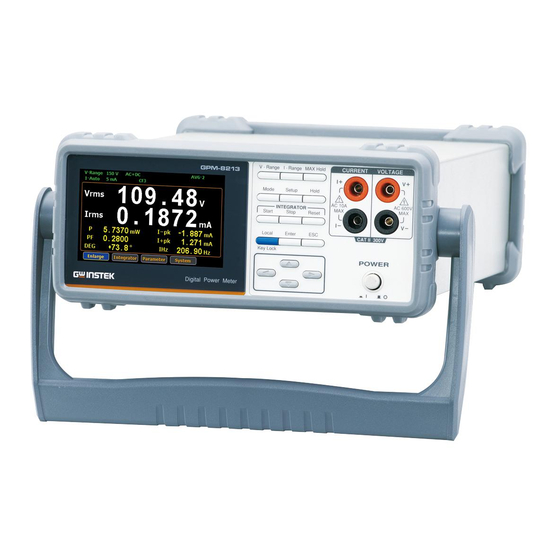
GPM-8213 User Manual Characteristics The GPM-8213 is a high-precision, programmable power meter for using in standby measuring the device with low power such as switching power supplies, transformers, power supplies, adapter and other devices. It equips with a color TFT-LCD screen which is very convenient for reading the measurement results. - Page 11 GETTING STARTED 6 selectable voltage ranges available from 15V to Performance 300V with 0.1% of reading + 0.1% of range. 12 selectable current ranges available from 5mA to 20A with 0.1% of reading + 0.1% of range. It can even measure the voltage of abnormal ...
- Page 12 GPM-8213 User Manual It can be applied to production test such as Application power supplies, transformers, motors, electrical equipment and other equipment with low standby power. It can be applied to power measurement conforms to IEC 62301 It can be applied to assess the power ...
-
Page 13: Appearance
GETTING STARTED Appearance Front Panel V − Range I − Range MAX Hold CURRENT VO AGE GPM‐8213 Mode Setup Ho d AC 10A AC 600V NTEGRATOR Start Stop Reset Local Enter CAT II 300V Key Lock POWER D g tal Power Meter POWER Turns On or Off... - Page 14 The maximum measurable current and voltage are 600 V and 10A for voltage and current terminals of the front Warning panel of the GPM-8213. Do not input exceeded voltage and current, otherwise it will burn the device. V-Range key, up/down arrow keys...
- Page 15 GETTING STARTED Press this button to display the maximum measurement reading. See page 48. Press this key to select measure mode (DC/AC/AC+DC). See page Press this key to enter the measurement settings menu. See page 30. Press this key to switch window and stop refreshing.
- Page 16 GPM-8213 User Manual Press this button to cancel the Cancel (Exit) button current setting. The cursor returns to the default position or return to the previous menu according to the situation. See page 49. This for arrow keys are used...
-
Page 17: Display Overview
GETTING STARTED Display Overview Voltage Range Mode Max. Hold Average Range Current Range Remot e Filter KeyLock Display Hold Peak Voltage Peak Current Main Measurement Display Minor Measurement Display Remot e Error Secondary Menus Status icon Description Item V_Range 300V Voltage measurement range. Voltage Range Example here range is 300V. - Page 18 GPM-8213 User Manual External current magnification CT Ratio State (on/off) Max. Hold Retain and display the maximum Maximum Hold measurement reading. KeyLock Lock Key button Keyboard Lock Avg-1 Average number of sampling Average (1/2/4/8/16/32/64) Hold Retain and display the current Display Hold measurement reading.
- Page 19 GETTING STARTED System This function key is used to enter the system setting and system configuration screens.
-
Page 20: Rear Panel
GPM-8213 User Manual Rear Panel CURRENT VOLTAGE R 232 600V WARNING TO AVOID SHOCK, CAT I 300V REMOVE NPUTS BEFORE OPENING. GP B SER.NO. LABEL 240V 50 / 60Hz 25VA MAX Power Cord Accepts the power cord. Socket AC 100~240V ±10%,... - Page 21 The maximum measurable current and voltage are 600 V and 20A for voltage and current terminals of the rear panel of the GPM-8213. Do not input exceeded voltage and current, otherwise it will burn the device. Always use the supplied cable for connection.
-
Page 22: Set Up
GPM-8213 User Manual Set Up Tilting the Stand From the base of the handle, gently pull the handle out sideways and then rotate it to one of the following positions. Horizontal position Tilt stand position Carry position... -
Page 23: Power Up
GETTING STARTED Power Up 1. Ensure the AC voltage is 100~ 240V. Steps 2. Connect the power cord to the AC voltage input. Make sure the ground connector on the power Note cord is connected to a safety ground. This will influence the measurement accuracy. -
Page 24: Connect The Wires To The Gpm-8213
GPM-8213 User Manual Connect the wires to the GPM-8213 Two separate wires is used to connect the Background GPM-8213, so voltage and current measurement are isolated and don’t interfere with each other. CURRENT VOLTAGE Connection diagram CAT II 300V The terminals on the front and rear panels can’t be Note used as input terminal at the same time. -
Page 25: Basic Setting
BASIC SETTING ASIC SETTING Setting up measurement range ......... 26 Auto Range ..............28 Setting up measurement status ........ 30 Setting up synchronization source ......30 Setting up filter ............31 Setting up crest factor ..........32 ... -
Page 26: Setting Up Measurement Range
GPM-8213 User Manual Setting up measurement range To get the accurate measurement results, you should set an appropriate measurement range before you perform measurement task. Set voltage range 1. Press V-Range button. 2. Use up and down arrow keys to select the desired range. - Page 27 BASIC SETTING 2. Use up and down arrow keys to select the desired range. 3. Press Enter button to confirm your selection. Available range Crest Factor AUTO, 5mA, 10mA, 20mA, 50mA, is 3: 100mA, 200mA, 0.5A, 1A, 2A, 5A,10A, Crest Factor AUTO, 2.5mA, 5mA, 10mA, 25mA, is 6: 50mA, 100mA, 250mA, 0.5A, 1A, 2.5A,...
-
Page 28: Auto Range
GPM-8213 User Manual The P.V status icon lights in red when the voltage Note measurement circuit detects that the measured value exceeds setting range by 3 folds (CF is set to 3) or 6 folds (CF is set to 6). - Page 29 BASIC SETTING Example Irms exceeds the current setting range by 110%, so range is shifted to 20mA Irms is less than or equal to 60% of the previous setting range, so range is shifted down to 10mA. Test Equipment Depot - 800.517.8431 - 99 Washington Street Melrose, MA 02176 TestEquipmentDepot.com...
-
Page 30: Setting Up Measurement Status
GPM-8213 User Manual Setting up measurement status Setting up synchronization source 1. Press Setup button. Steps 2. Press Enter button. 3. Press down arrow key. 4. Press Enter button to enter Sync Source item. Use up and down arrow keys to select the desired option and then press Enter button again to confirm your selection. -
Page 31: Setting Up Filter
BASIC SETTING Setting up filter 1. Press Setup button. Steps 2. Press Enter button. 3. Press down arrow key twice. 4. Press Enter button to enter Filter item. Use up and down arrow keys to select the desired option and then press Enter button again to confirm your selection. -
Page 32: Setting Up Crest Factor
GPM-8213 User Manual Setting up crest factor 1. Press Setup button. Steps 2. Press Enter button. 3. Press down arrow key three times. 4. Press Enter button to enter Crest Factor item. Use up and down arrow keys to select the desired option and then press Enter button again to confirm your selection. -
Page 33: Setting Up Auto-Zero Function
BASIC SETTING Setting up auto-zero function 1. Press Setup button. Steps 2. Press Enter button. 3. Press down arrow key four times. 4. Press Enter button to enter Auto Zero item. Use up and down arrow keys to select the desired option and then press Enter button again to confirm your selection. -
Page 34: Setting Up Average Value
GPM-8213 User Manual Setting up average value 1. Press Setup button. Steps 2. Press Enter button. 3. Press down arrow key five times. 4. Press Enter button to enter Average item. Use up and down arrow keys to select the desired option and then press Enter button again to confirm your selection. -
Page 35: Setting Up Method Of Calculating Harmonics
BASIC SETTING Setting up method of calculating harmonics 1. Press Setup button. Steps 2. Press Enter button. 3. Press down arrow key six times. 4. Press Enter button to enter Harmonics item. Use up and down arrow keys to select the desired option and then press Enter button again to confirm your selection. -
Page 36: Setting Up The Pt Ratio Status
GPM-8213 User Manual Setting up the PT ratio status 1. Press Setup button. Steps 2. Press Enter button. 3. Press down arrow key seven times. 4. Press Enter button to enter PT Ratio Status item. Use up and down arrow keys to select the... -
Page 37: Setting Up The Ct Ratio Status
BASIC SETTING Setting up the CT ratio status 1. Press Setup button. Steps 2. Press Enter button. 3. Press down arrow key eight times. 4. Press Enter button to enter CT Ratio Status item. Use up and down arrow keys to select the desired option and then press Enter button again to confirm your selection. -
Page 38: Setting Up System Status
GPM-8213 User Manual Setting up System status System configuration setting screen 1. Use left and right arrow keys on Steps the front panel to select System function key. 2. Press Enter button to Enter SYSTEM INFORMATION setting screen. 3. Press right arrow key to select Config key. -
Page 39: Setting Up Brightness
BASIC SETTING 2. Press Enter button to enter Power On Status Setup item. Use up and down keys to select the desired option and then press Enter button again to confirm your selection. Option Previous: The status of device on powering on is set to the status before the last shutdown. -
Page 40: Setting Up Key Sound
GPM-8213 User Manual 2. Press Enter button to enter Brightness item. Use up and down keys to select a number and then press Enter button again to confirm your selection. Option 1 to 9 The display is the darkest when set to 1. -
Page 41: Setting Up Interface
BASIC SETTING 2. Press Enter button to enter Key Sound item. Use up and down arrow keys to select the desired option and then press Enter button again to confirm your selection. Option A short sound is heard from the speaker of device when pressing the keys on the front panel. - Page 42 GPM-8213 User Manual 2. Press Enter button to enter I/O Model item. Use up and down arrow keys to select the desired option and then press Enter button again to confirm your selection. Option RS232: If interface is set to RS232, the Baud Rate can be selected from the following options.
-
Page 43: Configure Rs232 Interface
Configure RS232 Interface RS232 Selectable Baud rate 1200, 2400, 4800, 9600, Configuration 19200, 38400, 57600, 115200 Parity None Hardware flow control Data Bits Stop bit RS232 Pin Pin 2: RxD Assignments Pin 3: TxD Pin 5: GND Pin 1, 4, 6 ~ 9: No Connection Use a Null Modem connection as shown in the PC Connection... -
Page 44: Measurement And Other Functions
GPM-8213 User Manual EASUREMENT AND OTHER FUNCTIONS Measurement function ..........45 Introduction to measurement parameters ....45 Setting measurement parameters ......46 Other functions ............48 Introduction to other functions ......... 48 Integration measurement function ......50 Setting up Integrator measurement ......50 Introduction to integrator parameters ...... -
Page 45: Measurement Function
MEASUREMENT AND OTHER FUNCTIONS Measurement function The GPM-8213 provides a wide range of basic electricity and power measurement functions. It equips with different accurate measurement parameters for accurately measuring the voltage, current, power, DC/AC/AC + DC, power factor, harmonics, frequency, etc. The input impedance of the device is 2.4MΩ, the maximum input voltage is 600Vrms. -
Page 46: Setting Measurement Parameters
GPM-8213 User Manual P+pk and P-pk Active Power Peak THDI and THDV Total Harmonic Distortion CFV, CFI Crest factor Setting measurement parameters Please follow the steps blow to set the measurement parameters 1. Use left and right arrow keys on... - Page 47 MEASUREMENT AND OTHER FUNCTIONS 5. In standard display mode, you Switching display mode simply press the Enter button to switch display mode to simple one. 6. Press ESC button to return back to original display mode. Test Equipment Depot - 800.517.8431 - 99 Washington Street Melrose, MA 02176 TestEquipmentDepot.com...
-
Page 48: Other Functions
GPM-8213 User Manual Other functions Introduction to other functions Function name Button Description When the MAX Hold button is MAX Hold pressed, the MAX Hold status icon will light in red in the LCD display to indicate that this function is activated. - Page 49 MEASUREMENT AND OTHER FUNCTIONS When the Hold button is pressed, the Hold Hold status icon will light in red in the LCD display to indicate that this function is activated. To deactivate this function, press this button again. When the Hold function is activated, the displayed value on the LCD display is not updated and the range is locked.
-
Page 50: Integration Measurement Function
GPM-8213 User Manual Integration measurement function Setting up Integrator measurement 1. Use left and right arrow keys on steps the front panel to select Integrator function key. 2. Press Enter button to enter the integrator measurement screen. 3. Press right arrow key to select Set key. - Page 51 MEASUREMENT AND OTHER FUNCTIONS 4. Press Enter button to enter Select integrator measurement integrator measurement setting mode screen. 5. Press Enter button to enter Mode item. Use up and down arrow keys to toggle between Manual and Standard mode. Press Enter button again to confirm your selection.
- Page 52 GPM-8213 User Manual If you select standard mode, you need to set integrator measurement time before using integrator function. It can be set from 1 second to 9999 hours, 59 minutes and 59 seconds. 6. Press down arrow key to select Function item in the integrator measurement setting screen.
-
Page 53: Introduction To Integrator Parameters
MEASUREMENT AND OTHER FUNCTIONS Introduction to integrator parameters Parameter name Description Manual Mode Standard Watt Hours Function WP: Total power WP+: Positive total power WP-: Negative total power Ampere Hours q: Total mAh q+: Positive total q-: Negative total It indicates the time of integrator measurement to Set time... - Page 54 GPM-8213 User Manual Running State Integrator measurement is in progress. Stop Integrator measurement has been stopped manually. Timeout The time for running integrator measurement is up. Reset The integrator measurement status is cleared.
-
Page 55: Using The Integrator Function
MEASUREMENT AND OTHER FUNCTIONS Using the integrator function 1. In manual mode, you can directly Manual mode Start press the Start button in the front panel to start integrator function. Stop 2. To stop integration function, press the Stop button in the front panel. 3. - Page 56 GPM-8213 User Manual 1. Set integrator measurement time before using Standard mode integrator function. 2. Other steps are same as running in manual mode. When integrator performing, the test time will increase until the setting integrator measurement time. In the integration process, select the Measure ...
-
Page 57: Appendix
APPENDIX PPENDIX Specifications ............58 Input ................58 Display ................ 59 Voltage Measurement ..........59 Current Measurement ..........60 Power Measurement ..........60 Frequency Measurement ........... 61 Integrator Measurement ..........61 Dimensions ............62 Declaration of Conformity ........ -
Page 58: Specifications
GPM-8213 User Manual Specifications Below are the basic conditions required to operate the GPM-8213 within specifications: Calibration: Yearly 18~28 ˚C (64.4~82.4˚F) Operating Environment: Humidity: <80%RH, Accuracy: ± (% of reading + % of range) The specifications apply when it warmed up for at least 30 ... -
Page 59: Display
APPENDIX Display Synchronization frequency 45Hz~ 6kHz Average 1, 2, 4, 8, 16, 32, 64 Displayed items(Standard mode) 8 items simultaneously. Displayed items(Simple mode) 4 items simultaneously. Displayed digits Voltage converter 1 to 9999.999 Current converter 1 to 9999.999 Voltage, current, active power, apparent power, reactive power, power factor, phase angle, frequency, integrated current, integrated power,... -
Page 60: Current Measurement
GPM-8213 User Manual Temperature 5-18˚C / 28-40˚C Increase ±0.03% reading /˚C effect Residual noise 0.5 % of range Current Measurement 5mA, 10mA, 20mA, 50mA, CF=3 : 100mA, 200mA, 500mA, 1A, 2A, 5A, 10A, 20A Measurement range 2.5mA, 5mA, 10mA, 25mA, CF=6 : 50mA, 100mA, 250mA, 0.5A,... -
Page 61: Frequency Measurement
APPENDIX Frequency Measurement The filter is turned on 30.000Hz to 499.99Hz Measurement range The filter is turned off 30.000Hz to 9.9999kHz Measurement items Voltage, Current 10% to 105% of voltage input Effective input range range Accuracy ±(0.06 % reading) Integrator Measurement Integrator Accuracy ±(Accuracy of voltage or current+ 0.1 % reading) Range... -
Page 62: Dimensions
GPM-8213 User Manual Dimensions Test Equipment Depot - 800.517.8431 - 99 Washington Street Melrose, MA 02176 TestEquipmentDepot.com... -
Page 63: Declaration Of Conformity
GOOD WILL INSTRUMENT CO., LTD. declare that the below mentioned product Type of Product: Digital Power Meter Model Number: GPM-8213 are herewith confirmed to comply with the requirements set out in the Council Directive on the Approximation of the Law of Member States relating to EMC (2014/30/EU), LVD (2014/35/EU), WEEE (2012/19/EU) and RoHS (2011/65/EU). -
Page 64: Power Measurement
GPM-8213 User Manual Power measurement Direct read method: Directly read the Method measurement value measured from power measuring instrument. The average power method: Record the actual power value within a settable time and then take the average. Settable time isn’t less than 10min. - Page 65 APPENDIX Large current: Voltage measurement mode measured from load side (Connect to ammeter externally). The voltage measurement is accurate. The current measurement on load could be larger than the actual one due to leakage current of multi-measurement voltage.
-
Page 66: Introduction To Iec-62301
Turning off the auto range function is available. Harmonic bandwidth is greater than or equal to 2.5kHz. The GPM-8213 meets all of the features listed above. Test Equipment Depot - 800.517.8431 - 99 Washington Street Melrose, MA 02176 TestEquipmentDepot.com... -
Page 67: Eup Directive Lot6 Specifications
APPENDIX EUP Directive Lot6 specifications Ecodesign directive for energy-using products: The power loss requirement for the products with external power supply such as information devices, consumer electronics product, household appliances, toys, entertainment and sports products and so on in standby and off mode is as below. Mode/Limit 2010.01 2013.01 ≦...
Need help?
Do you have a question about the GPM-8213 and is the answer not in the manual?
Questions and answers