Sign In
Upload
Download
Table of Contents
Contents
Add to my manuals
Delete from my manuals
Share
URL of this page:
HTML Link:
Bookmark this page
Add
Manual will be automatically added to "My Manuals"
Print this page
×
Bookmark added
×
Added to my manuals
Manuals
Brands
GW Instek Manuals
Measuring Instruments
GPM-8320
User manual
GW Instek GPM-8320 User Manual
Digital power meter
Hide thumbs
1
2
3
4
5
6
7
8
9
10
11
12
13
14
15
16
17
18
19
20
21
22
23
24
25
26
27
28
29
30
31
32
33
34
35
36
37
38
39
40
41
42
43
44
45
46
47
48
49
50
51
52
53
54
55
56
57
58
59
60
61
62
63
64
65
66
67
68
69
70
71
72
73
74
75
76
77
78
79
80
81
82
83
84
85
86
87
88
89
90
91
92
93
94
95
96
97
98
99
100
101
102
103
104
105
106
107
108
109
110
111
112
113
114
115
116
117
118
119
120
121
122
123
124
125
126
127
128
129
130
131
132
133
134
135
136
137
138
139
140
141
142
143
144
145
146
147
148
149
150
151
152
153
154
155
156
157
158
159
160
161
162
163
164
165
166
167
168
169
170
171
172
173
174
175
176
177
178
179
180
181
182
183
184
185
186
187
188
189
190
191
192
193
194
195
196
197
198
199
200
201
202
203
204
205
206
207
208
209
210
211
212
213
214
215
216
217
218
219
220
221
222
223
224
225
226
227
228
229
230
231
232
233
234
235
236
237
238
239
240
241
242
243
244
245
246
page
of
246
Go
/
246
Contents
Table of Contents
Bookmarks
Table of Contents
Table of Contents
Safety Instructions
Getting Started
Characteristics
Accessories
Package Contents
Appearance
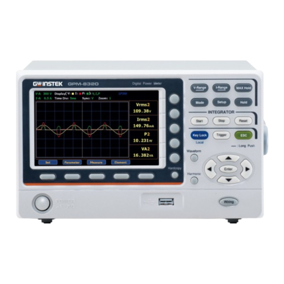
Front Panel
Gpm-8320/8330
Main Display Overview
Rear Panel
Gpm-8330
GPM-8330 (Without GPIB +DA 12 Interface)
Gpm-8320
Set up
Power up
Connect the Wires to the GPM-8320/8330
Basic Setting
Setting up Measurement Range
Auto Range
Setting up Measurement Status
Setting up Synchronization Source
Setting up Line Filter
Setting up Frequency Filter
Setting up Crest Factor
Setting up Auto-Zero Function
Setting up Method of Calculating Harmonics
Setting up Data Update Rate
Setting up Measure Storage
Setting up Average Function
Setting up the Voltage and Current Skipping Configuration46
Setting up the Skipping Configuration for External
Setting up the Element for Ratio
Setting up the VT Ratio State
Setting up the CT Ratio State
Setting up the Power Ratio State
Setting up the External Sensor Input Terminal
Saving and Loading the Setup Parameters
Setting up the D/A Output Configuration
Setting up the Hardcopy and Log Configuration
Setting up the MATH Configuration
Setting up System Status
System Information Screen
SYSTEM CONFIG1 Screen
Setting up Power on Status
Setting up Brightness
Setting up Key Sound
Setting up Remote Interface
SYSTEM CONFIG2 Screen
Setting up SCPI Identity
Measurement and Other Functions
Measurement Function
Introduction to Measurement Parameters
Measurement Display Pages Overview
Setting Measurement Parameters
Changing the Numeric Display
Changing the Standard and Simple Display Modes
Other Functions
Introduction to Other Functions
Integration Measurement Function
Setting up Integrator Measurement
Introduction to Integrator Parameters
Using the Integrator Function
Graph Measurement Function
Setting up Waveform Graph Measurement
Setting up Waveform Graph Parameter and Element
Setting up Harmonics Bar Graph Measurement and Element
Setting up Harmonics List Graph Measurement
Digital I/O / Da12
Digital I/O / DA12 Overview
External Remote Control
DA12 Output Function
Remote Control
Configure Remote Control Interface
Configure USB Interface
Configure RS232 Interface
Configure GPIB Interface
Configure LAN Interface
Configure EOL Character
Return to Local Control
Command Overview
Command Syntax
Command List
Cls
Ese
Esr
Idn
Opc
Opt
Rst
Sre
Stb
Trg
Aoutput
Aoutput[:Normal]:Channel<X
Aoutput[:Normal]:Irtime
Aoutput[:Normal]:Mode<X
Aoutput[:Normal]:Preset
Aoutput[:Normal]:Rate<X
Aoutput:digital:mode
Aoutput:digital:output
Aoutput:digital:setup
Communicate
Communicate:header
Commands :Communicate:lockout
Communicate:remote
Communicate:lockout
Communicate:status
Communicate:verbose
Display
Display:normal
Commands :Display[:Normal]:Item<X
Display[:Normal]:Item<X
Display:integrate:item<X
Display:page
Display:numeric[:Normal]:Format
Display:numeric[:Normal]:Page
Display
Description
Harmonics
Harmonics:display
Command :Harmonics:display[:State]
Harmonics:display[:State]
Harmonics:display:order
Harmonics:pllsource
Harmonics:order
Harmonics:thd
Input
[:Input]:Wiring
[:Input]:Mode
[:Input]:Voltage
[:Input]:Voltage:range
[:Input]:Voltage:auto
[:Input]:Voltage:config
[:Input]:Voltage:pojump
[:Input]:Current
[:Input]:Current:range
[:Input]:Current:auto
[:Input]:Current:config
[:Input]:Current:pojump
[:Input]:Current:extsensor:config<X
[:Input]:Current:extsensor:pojump<X
[:Input]:Current:sratio:element<X><Y
[:Input]:Rconfig
[:Input]:Scaling
[:Input]:Scaling[:State]
[:Input]:Scaling:{Vt|Ct|Sfactor}:Element <X
[:Input]:Synchronize
[:Input]:Filter
[:Input]:Filter:line
[:Input]:Filter:frequency
[:Input]:Pover
[:Input]:Crange
[:Input]:Zero
Measure
Measure:averaging
Measure:averaging[:State]
Measure:averaging:type
Measure:averaging:count
Measure:mhold
Numeric
Numeric:format
Numeric:normal
Numeric[:Normal]:Value
Numeric[:Normal]:Number
Numeric[:Normal]:Item<X
Numeric[:Normal]:Preset
Numeric[:Normal]:Clear
Numeric[:Normal]:Delete
Numeric[:Normal]:Header
Numeric:list
Numeric:list:value
Numeric:list:number
Numeric:list:order
Numeric:list:select
Numeric:list:item<X
Numeric:list:preset
Numeric:list:clear
Numeric:list:delete
Numeric:hold
Status
Status:condition
Status:eese
Status:eesr
Status:error
Status:filter<X
Status:qenable
Status:qmessage
System
System:brightness
System:communicate:command
System:communicate:ethernet:macaddress
System:firmware:date
System:klock
System:model
System:resolution
System:serial
System:version[:Firmware]
Appendix
Specifications
General Specifications
Input
Voltage and Current Accuracy
Active Power Accuracy
Voltage, Current and Active Power Measurements
Frequency Measurement
Integration
Harmonic Measurement
D/A Output (Options)
Remote Control Input/Output Signal (Options)
Status System
Dimensions
Certificate of Compliance
Power Measurement
Measurement for Small Current
Measurement for Large Current
Measurement Function
Advertisement
Quick Links
Download this manual
Digital Power Meter
GPM-8320/8330
USER MANUAL
Rev. A
ISO-9001 CERTIFIED MANUFACTURER
Ihr Ansprechpartner /
Your Partner:
dataTec AG
E-Mail: info@datatec.eu
>>> www.datatec.eu
Table of
Contents
Previous
Page
Next
Page
1
2
3
4
5
Advertisement
Chapters
Table of Contents
3
Etting Started
10
Asic Setting
27
Easurement and Other Functions
80
Emote Control
134
Command List
147
Aoutput Commands
155
Communciate Commands
160
Display Commands
164
Harmonics Command
169
Input Commands
173
Measure Commands
191
Status Commands
217
Ppendix
228
Table of Contents
Need help?
Do you have a question about the GPM-8320 and is the answer not in the manual?
Ask a question
Questions and answers
Related Manuals for GW Instek GPM-8320
Measuring Instruments GW Instek gpm-8212 User Manual
Power meter (6 pages)
Measuring Instruments GW Instek 82PM-82120MB User Manual
Ac power meter (14 pages)
Measuring Instruments GW Instek GPM-8213 User Manual
Digital power meter (114 pages)
Measuring Instruments GW Instek GPM-8213 User Manual
Digital power meter (67 pages)
Measuring Instruments GW Instek GPT-10000 Series User Manual
Electrical safety analyzer (224 pages)
Measuring Instruments GW Instek GPT-10000 Series Quick Start Manual
Electrical safety analyzer (24 pages)
Measuring Instruments GW Instek GPT-10000 Series User Manual
Electrical safety analyzer (263 pages)
Measuring Instruments GW Instek GPT-10000 Series User Manual
Electrical safety analyzer (288 pages)
Measuring Instruments GW Instek GPT-12000 Series User Manual
Electrical safety analyzer (224 pages)
Measuring Instruments GW Instek GPM-8310 User Manual
Digital power meter (251 pages)
Measuring Instruments GW Instek GPM-8310 Installation Manual
Digital power meter da4 installation (9 pages)
Measuring Instruments GW Instek GPM-8330 User Manual
Digital power meter (246 pages)
Measuring Instruments GW Instek GPT-15012 User Manual
Electrical safety analyzer (288 pages)
Measuring Instruments GW Instek GOM-802 User Manual
Milliohm meter (19 pages)
Measuring Instruments GW Instek GDM-8342 User Manual
Gdm-834x series. dual measurement multimeter (158 pages)
Measuring Instruments GW Instek GFC-8270H Manual
(10 pages)
This manual is also suitable for:
Gpm-8330
Table of Contents
Print
Rename the bookmark
Delete bookmark?
Delete from my manuals?
Login
Sign In
OR
Sign in with Facebook
Sign in with Google
Upload manual
Upload from disk
Upload from URL


Need help?
Do you have a question about the GPM-8320 and is the answer not in the manual?
Questions and answers