Gwinstek GSP-730, 82SP-73000MC1 - Spectrum Analyzer Quick Start Guide
- User manual (114 pages) ,
- Quick start manual (20 pages) ,
- Operating instructions manual (8 pages)
Advertisement
SAFETY INSTRUCTIONS
This section contains the basic safety symbols that may appear on the accompanying user manual CD or on the instrument. For detailed safety instructions and precautions, please see the Safety Instructions chapter in the user manual CD.
Safety Symbols
These safety symbols may appear in the user manual or on the instrument.
 | Identifies conditions or practices that could result in injury or loss of life. |
 | Identifies conditions or practices that could result in damage to the instrument or to other properties. |
 |  High Voltage |
 | Attention Refer to the Manual |
 | Protective Conductor Terminal |
 | Earth (ground) Terminal |
 | Do not dispose electronic equipment as unsorted municipal waste. Please use a separate collection facility or contact the supplier from which this instrument was purchased. |
Power Cord for the United Kingdom
When using the instrument in the United Kingdom, make sure the power cord meets the following safety instructions.
NOTE: This lead/appliance must only be wired by competent persons.

THIS APPLIANCE MUST BE EARTHED

The wires in this lead are coloured in accordance with the following code:

Green/ Yellow: Earth
Blue: Neutral
Brown: Live (Phase)
As the colours of the wires in main leads may not correspond with the coloured marking identified in your plug/appliance, proceed as follows:
The wire which is coloured Green & Yellow must be connected to the Earth terminal marked with either the letter E, the earth symbol ![]() or coloured Green/Green & Yellow.
or coloured Green/Green & Yellow.
The wire which is coloured Blue must be connected to the terminal which is marked with the letter N or coloured Blue or Black. The wire which is coloured Brown must be connected to the terminal marked with the letter L or P or coloured Brown or Red.
If in doubt, consult the instructions provided with the equipment or contact the supplier.
This cable/appliance should be protected by a suitably rated and approved HBC mains fuse: refer to the rating information on the equipment and/or user instructions for details. As a guide, a cable of 0.75mm2 should be protected by a 3A or 5A fuse. Larger conductors would normally require 13A types, depending on the connection method used.
Any exposed wiring from a cable, plug or connection that is engaged in a live socket is extremely hazardous. If a cable or plug is deemed hazardous, turn off the mains power and remove the cable, any fuses and fuse assemblies. All hazardous wiring must be immediately destroyed and replaced in accordance to the above standard.
GETTING STARTED
This chapter provides a brief overview of the GSP-730, the package contents, instructions for first time use and an introduction to the front panel, rear panel and GUI.
Main Features
| Performance |
|
| Features |
|
| Interface |
|
Package Contents
Please the package contents to ensure you have all of the following items:
| Part Number | Description User Manual CD Quick Start Guide (this document) |
| Region Dep. | Power cord x1 Cal. Certificate |
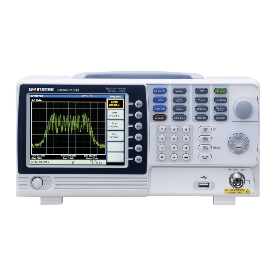
Display and Panel Overview
Display Overview

Description
- Reference level
- Marker information
- Function menu
- Soft menu keys
- Trace icons
- Entry/Message area
- Frequency / Bandwidth settings
- Trace and waveforms
Front Panel

Description
- LCD display
- Function keys
- Menu keys
- Hardcopy key
- Scroll wheel
- Arrow keys
- RF terminal input
- USB A port
- Keypad and unit keys
- Power button
Rear Panel

Description
- RS-232 port
- USB B port
- VGA output
- Security slot
- Fan
- Power socket
First Time Use Instructions
Use the procedures below when first using the GSP730 to tilt the stand, power up the instrument, update the firmware and restore the unit back to the default settings. Lastly, the Conventions sections will introduce you to the basic operating conventions used throughout the user manual. For further details, please see the user manual.
Tilting the Stand
The GSP-730 has two adjustable tabs at the front that can be used to position the instrument into two preset orientations.
Leaning position:

Set the tabs down to have the GSP-730 leaning backward.
Upright Position:

Set the tabs flat to have the GSP-730 in an upright position.
Power Up and Down
Power Up:
- Insert the AC power cord into the power socket.
![]()
- Press the power button to turn the GSP-730 on.
![]()


Power Down:

Press the power button to power down.
Software Update
The GSP-730 allows the software to be updated by end-users. Before using the GSP-730, please check the GW Instek website or ask your local distributor for the latest software.
The update file, MAIN1.BIN, must be placed in the root directory of a USB flash drive.
System Version:
- Press
![]() >Information[F4].
>Information[F4]. - The system version is displayed on the SW Ver[F4] icon.

 >Information[F4].
Update Software:
- Place the update file, MAIN1.BIN, into the root directory of a USB flash drive.
- Insert the USB flash drive into the USB port on the front panel.
- Press
![]() >Update From USB Flash[F5].
>Update From USB Flash[F5]. - Press Update Now[F3] to execute the update process.
- When the message ìProgrammed Successfulî is displayed, the software has completed the update.
- Reboot the system when the update procedure has finished by cycling the power button.
- Check the software version again to confirm the update procedure.
USB Driver Installation
If the type B USB port on the rear panel is to be used for remote control, then the USB driver must be installed. The USB driver is located in the CD that accompanied this manual.
Driver Installation:
- Ensure the GSP-730 is turned on.
- Connect the USB cable from the PC to the rear panel USB B port.
![]()
- Windows will automatically detect the GSP-730 as a new device.
- Follow the instructions to locate the driver on the accompanying CD and install the driver.
- To see if the driver has been successfully installed, you can check to see if the GSP-730 is recognized by the Windows Device Manager when the GSP730 in connected to the PC.
- In Windows XP go to: Start>Control Panel>Device Manager.
- The GSP-730 should be shown under the Ports (COM & LPT) node:
![]()
- If the USB driver installation fails, you can try to manually install the driver by right clicking on the AT91 USBSerial icon and selecting the Install option.


Restoring Default Settings
The factory default settings can be easily restored using the Preset key on the front panel. The default settings cannot be changed. See the user manual for a list of the factory default settings.
Restore Default Settings:
Press  .
.
- The spectrum analyzer will load the default factory settings.
Conventions
The following conventions are used throughout the user manual. Read the conventions below for a basic grasp of how to operate the GSP-730 menu system and front panel keys.
Soft Menu keys:
The F1 to F6 function keys on the right side of the display correspond directly to the soft-menu keys on their left.

Input Parameter Values:
Selecting this type of menu key will allow you to enter a new value with the numeric keypad or increment/decrement the value using the scroll wheel or number pad. See the parameter input description below for more details.

Toggle State:
Pressing this menu key will toggle the state. Notice that any soft-menu key that can be toggled will have the active parameter underlined.

Toggle State & Input Parameter:
Pressing this menu key will allow you to toggle the state of the function between on and off. When in the onstate, the parameter value can be manually edited. Use the numeric keypad to enter the new value or use the scroll wheel to increment/decrement the current value. Again, the setting that is underlined is the active setting.

Sub Menu:
Pressing the More menu key will enter a submenu.

Sub Menu to select parameter
Pressing this type of menu key will enter a submenu to select a parameter.

Active Function:
Pressing this type of menu key will activate that function. The menu key will be highlighted to show it is the active function.

Parameter Input
Parameter values can be entered using the numeric keypad, the scroll wheel and the arrow keys.

Using the numeric keypad:
When prompted to enter a parameter, use the number keys (0~9), the decimal key (.) and the minus key (-) to enter a value. After a value has been entered, the unit keys can be used to select the units.
The value of the parameter is shown at the bottom of the screen as it is edited.

Back Space:
Use the backspace key to delete the last character or number entered.
Using the scroll wheel:
Use the scroll wheel to alter the current value. Clockwise increases the value, anti-clockwise decreases the value. The scroll wheel is usually used for values that highly variable, such as the center frequency settings.
Directional arrows:
Use the directional arrows to select discrete parameters or to alter values by a coarser resolution than the scroll wheel. Left/down decreases the value, right/up increases the value. The directional arrows are usually used for values that are of a discrete nature, such as selecting a memory location.
SPECIFICATIONS
The specifications apply when the GSP is powered on for at least 30 minutes under +20°C~+30°C.
Frequency Specifications
| Frequency Range | |
| Setting Range | 150kHz to 3GHz |
| Center Frequency | |
| Setting Resolution | 0.1MHz |
| Accuracy | within ±50kHz (frequency span: 0.3GHz to 2.6GHz, 20 ±5°C) |
| Frequency Span | |
| Setting range | 1MHz to 3GHz |
| Accuracy | within ±3% (frequency span: 0.3GHz to 2.6GHz, 20 ±5°C) |
| Resolution Bandwidth | |
| Setting Range | 30KHz, 100KHz, 300KHz, 1MHz, nominal -3dB bandwidth |
| SBB Phase Noise | |
| -85dBc / Hz (typical, 500kHz offset, RBW : 30kHz, Sweep time: 1.5s, Span: 1MHz@1GHz) | |
| Inherent Spurious Response | |
| less than -45dBc @ -40dBm Ref. Level (typical less than -50dBc) | |
Amplitude Specifications
| Reference Level | |
| Input Range | +20 to -40dBm |
| Unit | dBm, dBV, dBµV |
| Average Noise Level | |
| ≤ -100dBm (typical, center frequency: 1GHz RBW: 30kHz) | |
| Frequency Characteristics | |
| within ±3.0dB @300MHz~2.6GHz, within ±6.0dB @ 80~300MHz, 2.6~3GHz | |
| Accuracy | Within ±2dB (1GHz); SPAN:5MHz; Ref. level 0dBm, input signal -10dBm |
| Input | |
| Input Impedance | 50ohm, nominal |
| Input VSWR | less than 2.0@input att≥10dB |
| Input damage level | +30dBm (CW average power), 25VDC |
| Input connector | N connector |
Sweep Specifications
| Sweep Time | |
| Range | 300ms to 8.4s, auto (not adjustable) |
| Accuracy | within ±2% ( frequency span: full span) |
General Specifications
| Interface | |
| RS-232C | Sub-D female-D 9 pins |
| USB Connector | USB Host/Device full speed supported |
| VGA Output | Sub-D female 15 pins |
| Display | 640*480 RGB color LCD |
Other Specifications
| Operating Temperature | 5 to 45°C (Guaranteed at 25 ±5°C, without soft carrying case) |
| Operating Humidity | less than 45°C / 90%RH |
| Storage Temperature | -20 to 60°C, less than 60°C / 70%RH |
| Dimensions | 296 (L) × 153 (W) × 105 (H) mm |
| Weight | Approx. 2.2kg |
| Power Source | AC 100~240V, 50/60Hz |
Dimensions

EC Declaration of Conformity
We
GOOD WILL INSTRUMENT CO., LTD. declare that the below mentioned product
Type of Product: Spectrum Analyzer Model Number: GSP-730 is herewith confirmed to comply with the requirements set out in the Council Directive on the Approximation of the Law of Member States relating to the EMC: 2014/30/EU, LVD: 2014/35/EU, WEEE: 2012/19/EU and RoHS: 2011/65/EU
For the evaluation regarding the Electromagnetic Compatibility and Low Voltage Directive, the following standards were applied:
| ◎ EMC | |
| EN 61326-1: EN 61326-2-1: | Electrical equipment for measurement, control and laboratory use –– EMC requirements (2013) |
| Conducted & Radiated Emission EN 55011: 2016 | Electrical Fast Transients IEC 61000-4-4: 2012 |
| Current Harmonics EN 61000-3-2: 2014 | Surge Immunity EN 61000-4-5: 2014 |
| Voltage Fluctuations EN 61000-3-3: 2013 | Conducted Susceptibility EN 61000-4-6: 2014 |
| Electrostatic Discharge EN 61000-4-2: 2009 | Power Frequency Magnetic Field EN 61000-4-8: 2010 |
| Radiated Immunity EN 61000-4-3: 2006+A1:2008+A2:2010 | Voltage Dip/ Interruption EN 61000-4-11: 2004 |
| Low Voltage Equipment Directive 2014/35/EU | |
| Safety Requirements | EN 61010-1: 2010 (Third Edition) EN 61010-2-030: 2010 (First Edition) |
GOODWILL INSTRUMENT CO., LTD.
No. 7-1, Jhongsing Road, Tucheng District, New Taipei City 236, Taiwan
Tel: +886-2-2268-0389
Fax: +886-2-2268-0639
Web: http://www.gwinstek.com
Email: marketing@goodwill.com.tw
GOODWILL INSTRUMENT (SUZHOU) CO., LTD.
No. 521, Zhujiang Road, Snd, Suzhou Jiansu 215011, China
Tel: +86-512-6661-7177
Fax: +86-512-6661-7277
Web: http://www.instek.com.cn
Email: marketing@instek.com.cn
GOODWILL INSTRUMENT EURO B.V.
De Run 5427A, 5504DG Veldhoven, The Netherlands
Tel: +31-(0)40-2557790
Fax: +31-(0)40-2541194
Email: sales@gw-instek.eu
This manual contains proprietary information, which is protected by copyright. All rights are reserved. No part of this manual may be photocopied, reproduced or translated to another language without prior written consent of Good Will Corporation.
The information in this manual was correct at the time of printing. However, Good Will continues to improve its products and therefore reserves the right to change the specifications, equipment, and maintenance procedures at any time without notice.
Good Will Instrument Co., Ltd. No. 7-1, Jhongsing Rd., Tucheng Dist., New Taipei City 236, Taiwan


Documents / Resources
References
Home-GW Instek
交流直流电源_大功率电子负载_数字源表_电子安规测试仪_泄漏电流测试仪_万用表_数字电桥_信号发生器_示波器_电池测试仪_数字功率计_直流微欧姆计_交直流分流器_交流毫伏表-固纬电子-固纬电源
Download manual
Here you can download full pdf version of manual, it may contain additional safety instructions, warranty information, FCC rules, etc.
Download Gwinstek GSP-730, 82SP-73000MC1 - Spectrum Analyzer Quick Start Guide
Advertisement


Need help?
Do you have a question about the GSP-730 and is the answer not in the manual?
Questions and answers