Ransburg 9060 Service Manual
Classic high voltage controller (hv3 - handguns)
Hide thumbs
Also See for 9060:
- Service manual (52 pages) ,
- Service manual (38 pages) ,
- Service manual (36 pages)
Table of Contents
Advertisement
Quick Links
SERVICE MANUAL
CP-17-02
AUGUST - 2017
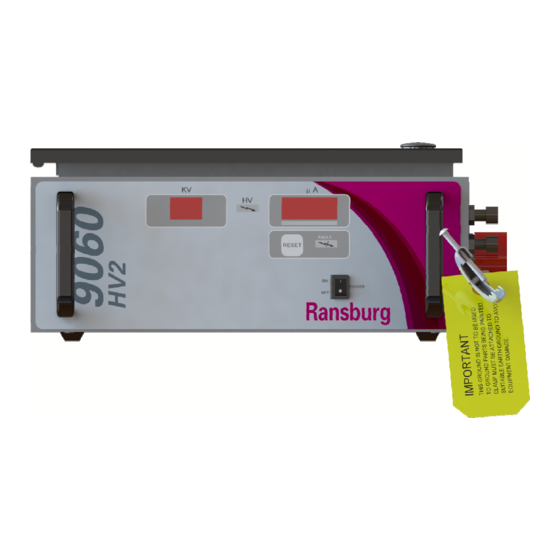
9060 CLASSIC HIGH VOLTAGE
IMPORTANT: Before using this equipment, carefully read SAFETY
PRECAUTIONS, starting on page 1, and all instructions in this manual.
Keep this Service Manual for future reference.
CONTROLLER
(HV3 - Handguns)
MODEL: 80180-212
Service Manual Price:
$50.00 (U.S.)
Ransburg
Advertisement
Table of Contents

Related Manuals for Ransburg 9060


Summary of Contents for Ransburg 9060
- Page 1 SERVICE MANUAL Ransburg CP-17-02 AUGUST - 2017 9060 CLASSIC HIGH VOLTAGE CONTROLLER (HV3 - Handguns) MODEL: 80180-212 IMPORTANT: Before using this equipment, carefully read SAFETY PRECAUTIONS, starting on page 1, and all instructions in this manual. Keep this Service Manual for future reference.
-
Page 2: Table Of Contents
9060 Classic High Voltage Controller - CONTENTS CONTENTS SAFETY: Safety Precautions ............................1 Hazards / Safeguards ............................. 2 INTRODUCTION: 6-11 General Description ............................6 Safety Features ...............................6 Displays ................................6 Specifications ..............................7 Controller Features ............................8 Operator Interface ............................9 Switches ................................9 LEDs ................................9 Buttons ................................9... - Page 3 9060 Classic High Voltage Controller - CONTENTS CONTENTS PARTS IDENTIFICATION: 29-31 9060 High Voltage Controller Model Identification..................29 Parts List................................ 30 Accessories ..............................31 WARRANTY POLICIES: Limited Warranty ............................32 CP-17-02...
-
Page 4: Safety
If you do not have the manuals and safety literature for your Ransburg system, contact your local Ransburg representative or Ransburg. -
Page 5: Hazards / Safeguards
9060 Classic High Voltage Controller - SAFETY SAFEGUARDS AREA HAZARD Tells how to avoid the hazard. Tells where hazards Tells what the hazard is. may occur. Spray Area Fire Hazard Improper or inadequate Fire extinguishing equipment must be present in operation and maintenance the spray area and tested periodically. - Page 6 9060 Classic High Voltage Controller - SAFETY SAFEGUARDS AREA HAZARD Tells how to avoid the hazard. Tells where hazards Tells what the hazard is. may occur. Explosion Hazard Spray Area Improper or inadequate Electrostatic arcing must be prevented. Safe operation and maintenance...
- Page 7 9060 Classic High Voltage Controller - SAFETY SAFEGUARDS AREA HAZARD Tells how to avoid the hazard. Tells where hazards Tells what the hazard is. may occur. Spray Area / Electrical Discharge High Voltage There is a high voltage device Parts being sprayed and operators in the spray...
- Page 8 9060 Classic High Voltage Controller - SAFETY SAFEGUARDS AREA HAZARD Tells how to avoid the hazard. Tells where hazards Tells what the hazard is. may occur. Electrical Discharge Electrical Equipment High voltage equipment is Unless specifically approved utilized in the process. Arcing...
-
Page 9: Introduction
The processor circuitry provides the maximum in applicator transfer efficiency, while maintaining the maximum safety. The 9060 Controller selection and adjustment of set point values is performed from the controller front panel. The triggering of the HV is normally initiated by... -
Page 10: Specifications
9060 Classic High Voltage Controller - INTRODUCTION SPECIFICATIONS Environmental: Operating Temperature: 0°C to +40°C, 32°F to +104°F Storage and Shipping Temperature: -40°C to +85°C, -40°F to +185°F (Allow power supply to go to room temperature before use) Humidity: 95% Non-Condensing... -
Page 11: Controller Features
9060 Classic High Voltage Controller - INTRODUCTION FRONT VIEW SIDE VIEW Figure 2: 9060 High Voltage Controller Features 9060 CONTROLLER FEATURES Description Description kV Display kV Setpoint/Adjust Buttons High Voltage On Indicator Air Flow Switch Hose Connections Reset Button High Voltage Cable Connector µA Display... -
Page 12: Operator Interface
Remote Mode LED Indicator The remote mode LED indicator should NOT be lit for handgun units. The 9060 Controller shown in Figure 3, has a simple operator interface consisting of 7 LEDs (Light Emitting Active Preset LED Indicators (3) Diodes), one (1) power switch, seven (7) buttons, one (1) -
Page 13: Connection Interface
This lug is provided as an external ground connection one (1) AC inlet receptacle. point used to ground the 9060 to an earth ground via a ground cable. This ground lug connection can also be used as the ground point for the high voltage cable CONNECTORS ground. -
Page 14: Fuses
Fault and HV on relay outputs. This is the source of their output voltage. It can be wired to either The 9060 controller local mode is used for handguns, an AC or DC signal. It is most commonly connected or very simple automatic gun systems. -
Page 15: Installation
Install the controller in an area outside the hazardous The following section contains general information on location in accordance with federal, state, and local the installation of 9060 High Voltage Controller. codes. The area should protect the controller from the possibility of environmental intrusion (such as... -
Page 16: Electrical Noise
(conduit) that makes contact to the shield (conduit) in a full 360° circle around the Using the methods previously described, the 9060 cable (conduit) and makes contact to the grounded Controller have been successfully tested to the stringent enclosure in the same fashion. -
Page 17: I/O Connections
Figure 8: I/O Cable Stripping AC INPUT CONNECTIONS For non-conduit installations, plug the detachable AC line cord into the receptacle on the side of the 9060 Controller. Plug the other end of the line cord into a properly grounded AC outlet. - Page 18 9060 Classic High Voltage Controller - INSTALLATION NOTE † In general, conduit must be used for approved AC installation, however, if national and local codes permit, the AC power may be supplied via the factory supplied line cord. If conduit is...
-
Page 19: Safety Ground
The 9060 Controller accepts universal input voltage between 100 and 240 VAC at 50 or 60 Hz. There is 1. Turn the 9060 Controller off, disconnect it from no need to change any switch settings when changing its AC source, and remove the fuses. - Page 20 9060 Classic High Voltage Controller - INSTALLATION Figure 12: Controller Schematic CP-17-02...
-
Page 21: High Voltage Cable
One of the listed flow W A R N I N G switches is mounted inside the 9060 Controller chassis via the Air Flow Switch Connector on the side panel. † The Controller MUST be OFF when the When the handgun trigger is pressed and flow starts, applicator is removed or reinstalled. - Page 22 INSTALLATION For reference, when replacing a flow switch, perform the following: 1. Turn the 9060 Controller off, disconnect it from its AC source, and remove the fuses. W A R N I N G † ALWAYS double check that the Controller is unplugged from its AC outlet before working with any internal wiring.
-
Page 23: Operation
11, 12 through the applicator. The flow of air activates the air flow switch which sends a trigger signal to the 9060 unit. The kV setpoint is displayed on the kV display, the actual current draw on the µA display, and the high voltage After the initial start-up delay, the unit will be configured light illuminates. -
Page 24: Lockouts
Figure 16: µA Bar Graph Meter Display Measuring “High Voltage On” Time The 9060 High Voltage Controller records the amount of time the high voltage is triggered on up to 99,999 hours. This value is display on the kV and µA displays of the unit. -
Page 25: Kv Test Jumper
JUMPER 17 INSTALLED Voltage Setpoints OVERLOAD ACTIVATED The voltage on the 9060 High Voltage Controller is adjustable between 20 kV and full kV DC. There are 3 Figure 20: Jumper Location - Overload Activation voltage setpoints (presets); 1, 2, and 3. Each of these... -
Page 26: Fault Descriptions
NOTE 9060 unit arise. If a fault occurs, to reset a fault, the trigger of the gun MUST be off and then press the Re- † The full kV DC value is determined by the set Button . - Page 27 9060 Classic High Voltage Controller - OPERATION Boot Fault (bF) This fault will occur during the start-up sequence if an GROUND FAULT ILLUMINATES FAULT active trigger signal is present. It is designed to prevent INDICATOR AND DISPLAYS “GF” immediate triggering after start-up as the unit should be allowed to enter the “ready”...
- Page 28 9060 Classic High Voltage Controller - OPERATION Voltage Cable Fault (UC) CURRENT LIMIT FAULT This fault will occur if the microprocessor detects ILLUMINATES FAULT a loss of the voltage feedback signal. This can be INDICATOR AND DISPLAYS “CL” caused by a failed high voltage cable, a failed high voltage section, or a failed pc board.
-
Page 29: Maintenance
9060 Classic High Voltage Controller - MAINTENANCE MAINTENANCE W A R N I N G † Before troubleshooting gun and control unit problems, flush the gun with solvent and purge with air. Some of the tests will require high voltage to be applied to the gun, so the gun must be empty of paint and solvent. - Page 30 9060 Classic High Voltage Controller - MAINTENANCE TROUBLESHOOTING GUIDE (Cont.) General Problem Possible Cause Solution The Ground Fault is typically caused by 1. Check for loose wiring between the pc board Ground a ground connection problem, and can connector and the high voltage section by Fault (GF) create a safety hazard.
- Page 31 9060 Classic High Voltage Controller - MAINTENANCE TROUBLESHOOTING GUIDE (Cont.) General Problem Possible Cause Solution Voltage Cable 1. Turn off the voltage controller and remove The Voltage Feedback Fault indicates the high voltage cable from the voltage Fault (UC) the cascade drive signal is not present.
-
Page 32: Parts Identification
9060 Classic High Voltage Controller - PARTS IDENTIFICATION PARTS IDENTIFICATION 9060 HIGH VOLTAGE CONTROLLER MODEL IDENTIFICATION* When ordering, use 80180-A1B as indicated by Tables A and B. Three (3) digits must follow the basic part number. For Example: 80180 - A 1B... -
Page 33: Parts List
Air Flow Switch (80130-21X, 31X, 51X Units) 13742-02 Air Flow Switch (80130-41X Units) 72771-06 Fuse (250V, 1A, 5mm x 20mm) 80116-80 9060 High Voltage Controller PC Mainboard for 80180-212 79428-00 Power Supply, 24V (24VDC Power Supply 1PS) 76434-01 Switch, Rocker (On-Off Switch) 79350-XX... -
Page 34: Accessories
9060 Classic High Voltage Controller - PARTS IDENTIFICATION 9060 HIGH VOLTAGE CONTROLLER - ACCESSORIES LIST Part No. Description 76652-01 HV Probe 76652-02 Meter w/Test Leads 76652-03 Paint Test Probe w/Meter 76652-04 Deluxe Kit (Include HV Probe, Meter w/Test Leads, and Paint Test Probe) -
Page 35: Warranty Policies
(any part number ending in “R”) for which the warranty period If, in Ransburg’s opinion the warranty item in question, is ninety (90) days. or other items damaged by this part was improperly... - Page 36 Ransburg Manufacturing 1910 North Wayne Street Angola, Indiana 46703-9100 Telephone: 260-665-8800 Fax: 260-665-8516 Technical Service — Assistance 320 Phillips Ave. Toledo, Ohio 43612-1493 Telephone (toll free): 800-233-3366 Fax: 419-470-2233 Technical Support Representative will direct you to the appropriate telephone number for ordering Spare Parts.
Need help?
Do you have a question about the 9060 and is the answer not in the manual?
Questions and answers