Table of Contents
Advertisement
Quick Links
SERVICE MANUAL
CP-13-05.3
FEBURARY — 2014
9060 HIGH VOLTAGE CONTROLLER
(HV1—Automatic Guns)
MODEL: 80100-XXX
IMPORTANT: Before using this equipment, carefully read
SAFETY PRECAUTIONS, starting on page 1, and all instructions
in this manual. Keep this Service Manual for future reference.
Service Manual Price:
Service Manual Price:
Service Manual Price:
Service Manual Price:
$50.00 (U.S.)
$50.00 (U.S.)
$50.00 (U.S.)
$50.00 (U.S.)
Advertisement
Table of Contents

Related Manuals for Ransburg 80100 Series


Summary of Contents for Ransburg 80100 Series
- Page 1 SERVICE MANUAL CP-13-05.3 FEBURARY — 2014 9060 HIGH VOLTAGE CONTROLLER (HV1—Automatic Guns) MODEL: 80100-XXX IMPORTANT: Before using this equipment, carefully read SAFETY PRECAUTIONS, starting on page 1, and all instructions in this manual. Keep this Service Manual for future reference. Service Manual Price: Service Manual Price: Service Manual Price:...
- Page 2 CP-13-05.3...
-
Page 3: Table Of Contents
9060 High Voltage Controller - Contents CONTENTS PAGE SAFETY: SAFETY PRECAUTIONS ......................1 HAZARDS / SAFEGUARDS....................2-5 INTRODUCTION: 7-16 GENERAL DESCRIPTION ......................7 SAFETY FEATURES ........................ 7 DISPLAYS ..........................7 SPECIFICATIONS ........................8 CONTROLLER FEATURES ...................... 9 OPERATOR INTERFACE ....................... 10 SWITCHES .......................... - Page 4 9060 High Voltage Controller - Contents CONTENTS PAGE OPERATION (Cont.): 29-42 LOCKOUTS ........................32-33 KV TEST JUMPER ......................... 33 REMOTE I/O MONITORING DIAGNOSTIC MODE ............33-35 PARAMETER ADJUSTMENT MODE ................35-36 LOCAL MODE ONLY OPERATIONS ................. 36-37 REMOTE MODE ONLY OERATIONS ................37-40 FAULT DESCRIPTIONS ....................
- Page 5 CP-13-05.3...
-
Page 6: Safety
Ransburg safety literature therein and understand all of the technical and safety identified. literature for your Ransburg products. This manual contains information that is important for you to know and understand. This infor- This manual MUST be read and thor-... -
Page 7: Hazards / Safeguards
9060 High Voltage Controller - Safety AREA HAZARD SAFEGUARDS Tells where hazards Tells what the hazard is. Tells how to avoid the hazard. may occur. Fire Hazard Fire extinguishing equipment must be present in Spray Area the spray area and tested periodically. Improper or inadequate opera- tion and maintenance proce- Spray areas must be kept clean to prevent the... - Page 8 9060 High Voltage Controller - Safety AREA HAZARD SAFEGUARDS Tells where hazards Tells what the hazard is. Tells how to avoid the hazard. may occur. Fire and/or explosion. Spray Area Electrostatic arcing MUST be prevented. The 78789 control panel, LEPS5001 power sup- ply and all other electrical equipment must be located outside Class I or II, Division 1 or 2 haz- ardous areas, in accordance with NFPA-33.
- Page 9 9060 High Voltage Controller - Safety AREA HAZARD SAFEGUARDS Tells where hazards Tells what the hazard is. Tells how to avoid the hazard. may occur. High voltage equipment is utilized. The power supply, optional remote control Electrical Arcing in areas of flammable or cabinet, and all other electrical equipment Equipment combustible materials may occur.
- Page 10 9060 High Voltage Controller - Safety AREA HAZARD SAFEGUARDS Tells where hazards Tells what the hazard is. Tells how to avoid the hazard. may occur. There is a high voltage Parts being sprayed must be supported on conveyors Spray Area / device that can induce an or hangers and be grounded.
- Page 11 9060 High Voltage Controller - Safety N O T E S CP-13-05.3...
-
Page 12: Introduction
Feedback Signal Faults, Overvoltage, and GENERAL DESCRIPTION Overcurrent. The microprocessor circuits provide a controlled output load curve, which The Ransburg 9060 High Voltage Control- limits the high voltage output to safe levels ler (80100-XXX) is used to provide high while... -
Page 13: Specifications
9060 High Voltage Controller - Introduction SPECIFICATIONS Environmental Operating Temperature: 0° C to +40° C Storage and Shipping Temperature: -40° C to +85° C (Allow power supply to go to room temperature before use) Humidity: 95% Non-Condensing Physical Height: 16.5 cm (6.5 inches) Width: 37.8 cm (14.9 inches) Depth:... -
Page 14: Controller Features
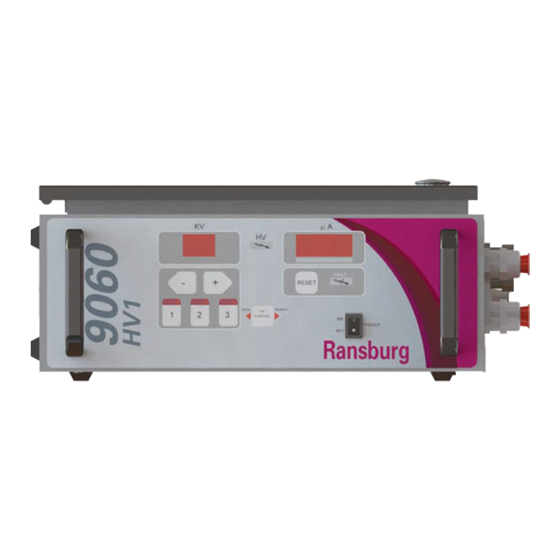
9060 High Voltage Controller - Introduction Figure 2: 9060 High Voltage Controller Features 9060 CONTROLLER FEATURES Description Description kV Display kV Setpoint/Adjust Buttons High Voltage On Indicator Optional Air Flow Switch Hose Connections Reset Button High Voltage Cable Connector µA Display Standard I/O Connector Fault Indicator Fuses... -
Page 15: Operator Interface
9060 High Voltage Controller - Introduction LOCAL Mode LED Indicator OPERATOR INTERFACE The LOCAL mode LED indicator is a left The 9060 Controller shown in Figure 3, has a pointing triangle and is located on the left side simple operator interface consisting of 7 LEDs the HV control button on the center of the (Light Emitting Diodes), one (1) power switch, operator interface. -
Page 16: Connection Interface
9060 High Voltage Controller - Introduction pressed with the reset button, at the same time, active, the unit will be in REMOTE mode, the screen will display the resettable High otherwise the unit will be in LOCAL mode. Voltage ON operating hours for 3 seconds on CONNECTION INTERFACE the display screens. -
Page 17: Fuses
9060 High Voltage Controller - Introduction HOT line (L) input connection and the Interlock I/O Connector Interlock AC line connection terminal TB1- The interlock I/O connector is located just L2. The bottom fuse holder is connected in above the AC inlet receptacle. This connector series between the neutral AC input connec- is provided as the entry point for interlock signal tion and the neutral input connection of the... -
Page 18: Signal Interface - Local Mode
9060 High Voltage Controller - Introduction relay signal is activated when a Fault Condi- SIGNAL INTERFACE - tion or Overload Condition has faulted the LOCAL MODE 9060 Controller. The 9060 Controller LOCAL mode is normal- Relay Common Input ly used for handguns, or very simple auto- The relay common input (TB2-3) is a shared matic gun systems. - Page 19 9060 High Voltage Controller - Introduction preset voltages that are normally selected N O T E during LOCAL mode operation via the three preset buttons on the left side of the front Sinking and Sourcing refers to the sig- panel. The two signals are used together as nal that is applied to activate an input.
- Page 20 9060 High Voltage Controller - Introduction control signal that adjusts the KV setpoint W A R N I N G scaled relative to the current signal applied. The allowable range for the current control DO NOT attempt to use both analog signal is 0-20mA mapped directly to a setpoint voltage and analog current at the same range of 0-100kV, or (2mA per 10kV).
- Page 21 9060 High Voltage Controller - Introduction High Voltage On (Relay Output N O T E S Dry Contact The “HV on” signal (TB2-4) is available in both LOCAL and REMOTE modes. This signal, being a relay controlled signal, can be config- ured as either an AC or DC signal using the Relay Common Input as the signal source.
-
Page 22: Installation
As each installation is unique, this infor- mation is intended to provide general in- stallation information for the 9060 Control- ler. Consult your authorized Ransburg distributor for specific directions pertaining to the installation of your equipment. Figure 5: Typical Controller Mounting... -
Page 23: Electrical Noise
9060 High Voltage Controller - Installation ELECTRICAL NOISE Electrical noise refers to stray electrical signals in the atmosphere at various signal strengths and frequencies that can affect the operation of equipment. One of the best ways to prevent this is to shield the equipment and cables within a continuous ground envelope, such that any incident noise will be conducted to earth ground before it can affect the circuit conductors. -
Page 24: I/O Connections
9060 High Voltage Controller - Installation affected by electrical noise when the above methods are utilized. I/O CONNECTIONS For maximum noise immunity, I/O wiring should be run in conduit or cables having a foil shield with an overall braided shield. The foil shield provides 100% shielding, while the braid provides a means of making proper 360°... - Page 25 9060 High Voltage Controller - Installation N O T E In general, conduit must be used for approved AC installation, however, if na- tional and local codes permit, the AC power may be supplied via the factory supplied line cord. If conduit is utilized, the Controller AC input wiring may be routed through an optional explosion proof switch mounted on or near the...
-
Page 26: Safety Ground
Controller ground automatically locked out whenever flush- stud to a true earth ground. ing occurs. Consult your authorized Ransburg representative for information on interlocking the high voltage OFF sig- INPUT VOLTAGE nal with the solvent flush signal. - Page 27 9060 High Voltage Controller - Installation Figure 12: Controller Schematic CP-13-05.3...
-
Page 28: High Voltage Cable
9060 High Voltage Controller - Installation of 300V and 105° C and its conductors W A R N I N G should be 0.8mm (18 AWG) minimum. Secure the cable to the interlock connector The Controller MUST be OFF when the as described in “I/O Connections”... -
Page 29: Local Mode Signals
9060 High Voltage Controller - Installation LOCAL MODE W A R N I N G (TRIGGER SIGNAL ONLY) The 9060 High Voltage Controller is designed to handle both a sinking or sourcing trigger input. The LOCAL mode is normally used only for handguns, or very simple automatic gun systems. -
Page 30: Remote I/O Mode Signals
(supplied by formation, consult your authorized user). Secure the cable to the standard I/O Ransburg distributor for specific directions connector as described in “I/O Connections” in pertaining to your installation or call Cus- the “Installation” section of this manual so that tomer Service. - Page 31 9060 High Voltage Controller - Installation The Relay Contact Outputs are normally 3. Route the selected shielded cable through included as output signal indicators for a control the standard I/O connector and secure it to system and are wired using a few of the con- the connector as described in “I/O Connec- ductors in the I/O cable.
- Page 32 9060 High Voltage Controller - Installation 6. The local/remote board (Assy# A13123), jumpers must be adjusted into one of the two REMOTE settings, based on the Terminal Block 2 (TB2) Terminal Block 3 desired input type, to allow for REMOTE mode operation.
- Page 33 9060 High Voltage Controller - Installation 8. Complete the control system I/O wiring be- N O T E S fore reconnecting the 9060 Controller to the AC source. 9. Secure the cabinet door, replace the fuses, and reconnect the AC source. 10.
-
Page 34: Operation
J10-J13. If they are incorrect, shown in Figure 18. These items are displayed contact your Ransburg representative. for approximately 5 seconds. USE ONLY the gun type configuration for the specific applicator being used. Us-... - Page 35 9060 High Voltage Controller - Operation onds. This is the resettable register. Triggering High voltage is actuated by the presence of an To reset this register, press the reset button active trigger signal. In LOCAL mode, this is while the hours are displayed. normally accomplished by pulling the trigger of the handgun to start the flow of atomizing and To view the non-resettable register, press the...
-
Page 36: Di/Dt Configuration (80100-51X Units Only)
9060 High Voltage Controller - Operation Adjusting DI/DT Parameters DI/DT CONFIGURATION The di/dt safety overload fault is configured (For 80100-51X Units Only) based upon two (2) parameters; Sensitivity The 9060 Voltage Controller, model 80100-51X, (SE), and Sample Time Interval (SA). These for use with the ATEX approved Aerobell 168 parameters can be adjusted in the Parameter applicator, contains a di/dt (rate of change in... -
Page 37: Lockouts
The overload circuit may be activated for safety reasons. These lockouts should applications that require overload indication or ONLY be modified by Ransburg Authorized notification of high current draws of the applica- Representatives. tor. The default overload value is set in the software to the maximum microamp rating minus 10 microamps. -
Page 38: Kv Test Jumper
N O T E N O T E Use Ransburg Calibrated Equipment Each time a signal monitoring sub mode ONLY for testing and troubleshooting. Re- is entered, the signal index is reset to zero fer to the “Accessories”... - Page 39 9060 High Voltage Controller - Operation Analog Signal Monitoring Mode To navigate through the analog indexes, use the - and + buttons. Both buttons change the In the analog signal monitoring mode the kV index by 1 for each press and will automatically display will show an “A#”...
-
Page 40: Parameter Adjustment Mode
9060 High Voltage Controller - Operation To navigate through the digital indexes, use the - and + buttons. Both buttons change the index by 1 for each press and will automatically wrap back around when the either end of the list is reached. -
Page 41: Local Mode Only Operations
9060 High Voltage Controller - Operation C A U T I O N Be careful when using the parameter adjustment mode, if you select something and are unsure if you’ve changed it, dese- lect it using Preset 2. Modifying a Parameter After a parameter has been selected using the preset 2 button and is flashing, the + and - keys can be used to increase or decrease... -
Page 42: Remote Mode Only Oerations
9060 High Voltage Controller - Operation REMOTE MODE ONLY OPERATIONS Remote Mode Control Behavior When operating in remote mode, the 9060 KV setpoint can be controlled by only one of two different sets of signals that are mutually exclusive: Tripleset Point Signals and Analog I/ O signals. - Page 43 9060 High Voltage Controller - Operation Tripleset Selection Setpoint 0 Selection Setpoint 1 0 (off) 0 (off) No Change 0 (off) 1 (on) Preset 1 1 (on) 0 (off) Preset 2 1 (on) 1 (on) Preset 3 N O T E Figure 33: Remote Mode Configuration Menu The display indicates the status of the The presets can NOT be adjusted in...
- Page 44 10 ms to reset the fault.. Then turn off the reset the unit may need recalibrated or re- signal. paired. Please contact your Ransburg representative. RESET SIGNAL TIMING: The 9060 Controller automatically trun-...
-
Page 45: Fault Descriptions
9060 High Voltage Controller - Operation TRIGGER SIGNAL TIMING: The trigger signal minimum hold time is 10 ms. C A U T I O N The signal Hold Times are the minimum required for the processor to detect the signal. During actual operations, signal time durations are expected to be much greater than the minimums. - Page 46 9060 High Voltage Controller - Operation Current Limit Fault (CL) This fault occurs if the output current exceeds the maximum current by 20µA. This fault can be caused by excessive overspray on the ap- plicator or a paint formulation that is too con- ductive.
- Page 47 DI/DT settings if necessary, and re- test operation. If this fault continues to occur, contact your Ransburg Representative. Figure 40: Over Voltage Fault Display Figure 42: DI/DT Overload Fault Display Feedback Fault (FF) This fault will occur if the microprocessor de- tects a loss of the current feedback signal.
-
Page 48: Maintenance
9060 High Voltage Controller - Maintenance MAINTENANCE TROUBLESHOOTING GUIDE General Problem Possible Cause Solution 1. No power 1. Check the power connections and verify Blank Display they are fully connected and power is avail- 2. Blown fuse able. Power cycle the unit off and back on. 3. - Page 49 9060 High Voltage Controller - Maintenance Fault Description Solution Ground Fault (GF) The Ground Fault is typically 1. Check for loose wiring between the pc caused by a ground connection board connector and the high voltage sec- problem, and can create a safety tion by pulling on each wire.
- Page 50 9060 High Voltage Controller - Maintenance Fault Description Solution The Voltage Feedback Fault indi- 1. Turn off the voltage controller and remove Voltage Cable cates the cascade drive signal is the high voltage cable from the voltage Fault (UC) not present. It typically occurs controller.
- Page 51 9060 High Voltage Controller - Maintenance N O T E S CP-13-05.3...
-
Page 52: High Voltage Controller Model Identification
9060 High Voltage Controller - Parts Identification PARTS IDENTIFICATION 9060 HIGH VOLTAGE CONTROLLER MODEL IDENTIFICATION * When ordering, use 80100-A1B as indicated by Table A and B. Three digits must follow the basic part number, for example: 80100 - A 1 B Basic Part Number Plug Selection (TABLE B) -
Page 53: Parts
9060 High Voltage Controller - Parts 9060 High Voltage Controller - Parts List Description Part # 72771-06 Fuse (250V, 1A, 5mm x 20mm) 80116-41 9060 High Voltage Controller PC Mainboard (for 80100-21X, 31X, 41X) 80116-68 9060 High Voltage Controller PC Mainboard (for 80100-51X) A13123-00 9060 High Voltage Controller Local/Remote Board 79350-01... -
Page 54: Accessories
9060 High Voltage Controller - Accessories ACCESSORIES 9060 High Voltage Controller - Accessories List Description Part # 76652-01 HV Probe 76652-02 Meter w/Test Leads 76652-03 Paint Test Probe w/Meter 76652-04 Deluxe Kit (Include HV Probe, Meter w/Test Leads, and Paint Test Probe) 76453-00 Conduit Adapter Kit CP-13-05.3... -
Page 55: Warranty Policies
THE USE OF OTHER THAN RANSBURG APPROVED PARTS, VOID ALL WARRAN- EXCLUSIONS: TIES. If, in Ransburg's opinion the warranty item in SPARE PARTS: One hundred and eighty (180) question, or other items damaged by this days from date of purchase, except for rebuilt part was improperly installed, operated or parts (any part number ending in "R") for which... -
Page 56: Wiring Configurations
9060 High Voltage Controller - Wiring Configurations WIRING CONFIGURATIONS COMMON REMOTE CONFIGURATIONS Remote Analog Voltage Control (Sourcing Configuration) The following example configuration uses the following: Sourcing Configured Digital Inputs (Apply 24VDC to activate the input) • Permanently Wired into Remote Mode (Jumper Wire from TB3-10 to TB3-2) •... - Page 57 9060 High Voltage Controller - Wiring Configurations Remote Analog Current Control (Sourcing Configuration) The following example configuration uses the following: Sourcing Configured Digital Inputs (Apply 24VDC to activate the input) • Permanently Wired into Remote Mode (Jumper Wire from TB3-10 to TB3-2) •...
- Page 58 9060 High Voltage Controller - Wiring Configurations Remote Tripleset Point Control (Sourcing Configuration) The following example configuration uses the following: Sourcing Configured Digital Inputs (Apply 24VDC to activate the input) • Normally Open (NO) Contact to Activate Reset when unit is Faulted •...
- Page 59 9060 High Voltage Controller - Wiring Configurations Remote Analog Voltage Control (Sinking Configuration) The following example configuration uses the following: Sinking Configured Digital Inputs (Apply GND to activate the input) • Permanently Wired into Remote Mode (Jumper Wire from TB3-11 to TB3-2) •...
- Page 60 Telephone (toll free): 800-233-3366 Fax: 419-470-2233 Technical Support Representative will direct you to the appropriate telephone number for ordering Spare Parts. Form No. CP-13-05.3 © 2013 Ransburg. All rights reserved. Litho in U.S.A. Models and specifications subject to change without notice. 02/14 CP-13-05.3...
Need help?
Do you have a question about the 80100 Series and is the answer not in the manual?
Questions and answers