Ransburg 9060 Service Manual
High voltage controller
hv1-automatic guns
Hide thumbs
Also See for 9060:
- Service manual (38 pages) ,
- Service manual (36 pages) ,
- Service manual (31 pages)
Table of Contents
Advertisement
SERVICE MANUAL
CP-13-05.4
MODEL:
IMPORTANT: Before using this equipment, carefully read SAFETY PRECAUTIONS, starting on
page 1, and all instructions in this manual. Keep this Service Manual for future reference.
CP-13-05.4 (10/2017)
9060 HIGH VOLTAGE
CONTROLLER
(HV1 - AUTOMATIC GUNS)
80100-XXX
1 / 52
www.carlisleft.com
Advertisement
Table of Contents

Related Manuals for Ransburg 9060


Summary of Contents for Ransburg 9060
- Page 1 SERVICE MANUAL CP-13-05.4 9060 HIGH VOLTAGE CONTROLLER (HV1 - AUTOMATIC GUNS) MODEL: 80100-XXX IMPORTANT: Before using this equipment, carefully read SAFETY PRECAUTIONS, starting on page 1, and all instructions in this manual. Keep this Service Manual for future reference. CP-13-05.4 (10/2017) 1 / 52 www.carlisleft.com...
- Page 2 MANUAL CHANGES NOTE: This manual has been changed from revision CP-13-05.3 to revision CP-13-05.4. Reasons for this change are noted under “Manual Change Summary” inside the back cover of this manual. CP-13-05.4 (10/2017) 2 / 52 www.carlisleft.com...
-
Page 3: Table Of Contents
Signal Interface - Local Mode ..........................15 Signal Interface - Remote Mode .......................... 16 INSTALLATION: 19-28 General Information ............................19 Location of the 9060 ............................19 Electrical Noise ..............................19 I/O Connections ..............................20 AC Input Connections ............................21 Safety Ground .............................. - Page 4 ............................42 Fault Troubleshooting Guide ..........................42 PARTS IDENTIFICATION: 45-46 High Voltage Controller Model Identification - Parts List ..................45 9060 High Voltage Controller - Parts List ......................46 Accessories ................................ 46 WIRING CONFIGURATIONS: 47-50 Common Remote Configurations ........................47...
-
Page 5: Safety
If you do not have the manuals and safety literature for your Ransburg system, contact your local Ransburg representative or Ransburg. CP-13-05.4 (10/2017) 5 / 52 www.carlisleft.com... -
Page 6: Hazards / Safegaurds
SAFETY Return To Contents AREA SAFEGUARDS HAZARD Tells where hazards Tells how to avoid the hazard. Tells what the hazard is. may occur. Fire Hazard Spray Area Fire extinguishing equipment must be present in the Improper or inadequate spray area and tested periodically. operation and maintenance procedures will cause a fire Spray areas must be kept clean to prevent the... - Page 7 SAFETY Return To Contents AREA SAFEGUARDS HAZARD Tells where hazards Tells how to avoid the hazard. Tells what the hazard is. may occur. Explosion Hazard Spray Area Improper or inadequate Electrostatic arcing must be prevented. Safe sparking operation and maintenance distance must be maintained between the parts being procedures will cause a coated and the applicator.
- Page 8 SAFETY Return To Contents AREA SAFEGUARDS HAZARD Tells where hazards Tells how to avoid the hazard. Tells what the hazard is. may occur. Spray Area / Electrical Discharge High Voltage There is a high voltage device Parts being sprayed and operators in the spray Equipment that can induce an electrical area must be properly grounded.
- Page 9 SAFETY Return To Contents AREA SAFEGUARDS HAZARD Tells where hazards Tells how to avoid the hazard. Tells what the hazard is. may occur. Electrical Discharge Electrical Unless specifically approved for use in hazardous Equipment locations, the power supply, control cabinet, and all High voltage equipment is utilized in the process.
-
Page 10: Introduction
The 9060 Controller can operate in either LOCAL mode or REMOTE mode conditions. In the LOCAL mode, the selection and adjustment of set point values is performed from the controller front panel. -
Page 11: Specifications
INTRODUCTION Return To Contents SPECIFICATIONS Environmental Operating Temperature: 0°C to +40°C Storage and Shipping Temperature: -40°C to +85°C (Allow power supply to go to room temperature before use) Humidity: 95% Non-Condensing Physical Height: 16.5 cm (6.5 inches) Width: 37.8 cm (14.9 inches) Depth: 30.7 cm (12.1 inches) Weight:... -
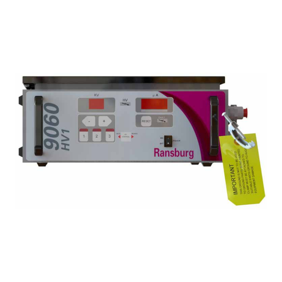
Page 12: Controller Features
INTRODUCTION Return To Contents FRONT VIEW SIDE VIEW Figure 2: 9060 High Voltage Controller Features 9060 CONTROLLER FEATURES Description Description kV Display kV Setpoint/Adjust Buttons High Voltage On Indicator Optional Air Flow Switch Hose Connections Reset Button High Voltage Cable Connector µA Display... -
Page 13: Operator Interface
The LOCAL mode LED indicator is a left pointing triangle and is located on the left side the HV control button on the The 9060 Controller shown in Figure 3, has a simple operator center of the operator interface. This LED is lit when the interface consisting of 7 LEDs (Light Emitting Diodes), one Controller is in LOCAL mode. -
Page 14: Connection Interface
4, provides all of the required connections for setting up lug is provided as an external ground connection point used either a remote I/O controlled painting system or a local to ground the 9060 to an earth ground via a ground cable. controlled painting system. This connection interface... -
Page 15: Fuses
High Voltage On (Relay Output, Dry Contact) High Voltage when the unit is not in the desired operating mode. As the 9060 Controller was designed to operate in The “HV on” signal (TB2-4) is available in both LOCAL and either LOCAL or REMOTE mode, it must be configured for REMOTE modes. -
Page 16: Signal Interface - Remote Mode
Digital Inputs when the Remote Mode Configuration is set to disable All of the digital inputs on the 9060 High Voltage Controller are Analog Control. For more information on how to configure 24 VDC signals that can be configured as either all sourcing Remote Mode, please see the Operation section of this or all sinking inputs. - Page 17 NOT be adjusted from REMOTE mode. than 2V, the KV setpoint is set to 0kV and the cascade To adjust the preset values stored in the 9060, the outputs no voltage. unit MUST be in LOCAL mode. If the voltage setpoint...
- Page 18 “Relay Output Contacts” portion of the “Installation” section of the manual. This relay signal is activated when a Fault Condition or Overload Condition has faulted the 9060 Controller. Relay Common Input The relay common input (TB2-3) is a shared connection between the Fault and HV on relay outputs.
-
Page 19: Installation
WA R N I N G The Controller may be free standing on any flat surface or † The 9060 Controller MUST be located outside of wall mounted (wall mount brackets not supplied) as shown the hazardous area. in Figure 5. -
Page 20: I/O Connections
Additional noise protection can be provided by running the AC input line to the control Using the methods previously described, the 9060 Controller panel in grounded conduit. have been successfully tested to the stringent standards of... -
Page 21: Ac Input Connections
Figure 8: I/O Cable Stripping AC INPUT CONNECTIONS For non-conduit installations, plug the detachable AC line cord into the receptacle on the side of the 9060 Controller. Plug the other end of the line cord into a properly grounded 110 volt AC outlet. -
Page 22: Safety Ground
INSTALLATION Return To Contents INPUT VOLTAGE SELECTION The 9060 Controller accepts universal input voltage be- tween 100 and 240 VAC at 50 or 60 Hz. There is no need to change any switch settings when changing input from 110 to 240 VAC or from 240 to 110 VAC. -
Page 23: High Voltage Cable
1. Turn the 9060 Controller off, disconnect it from its (129°F+). The operator should have free movement of AC source, and remove the fuses. -
Page 24: Controller Schematic
INSTALLATION Return To Contents Figure 12: Controller Schematic CP-13-05.4 (10/2017) 24 / 52 www.carlisleft.com... -
Page 25: Local Mode
The standard (optional) air flow switch (13742- To operate the Controller in the LOCAL mode, which uses 01 or 13742-02) used in the 9060 is wired as a only the high voltage trigger signal, perform the following: sinking switch. When the flow switch is activated, it connects the trigger signal input to ground. -
Page 26: Remote Mode External Signals
For any installation that includes a trigger signal that is connections in advance to determine the amount of generated by a switch or source that is external to the 9060 wire length required. Controller unit, the signal should be routed in through the standard I/O connector using a shielded cable (supplied by †... - Page 27 To operate the Controller in the REMOTE mode using any number of the discrete I/O signals, perform the following: Terminal Block 3 (TB3) 1. Turn the 9060 Controller off, disconnect it from its AC source, and remove the fuses. 2. Open the Controller cabinet door.
-
Page 28: Installation
INSTALLATION Return To Contents 8. Complete the control system I/O wiring before recon- REMOTE MODE JUMPER SETTINGS necting the 9060 Controller to the AC source. 9. Secure the cabinet door, replace the fuses, and recon- Jumper Remote Source Remote nect the AC source. -
Page 29: Operation
J10-J13. If they are incorrect, contact your Rans- turned on, the kV display will show the applicator type the burg representative. 9060 Controller is configured for and the µA (microamp) display will show the current software revision level as †... - Page 30 (see Accessory table) is activated, and the trigger signal is issued to the 9060 unit. In REMOTE mode, the control system logic DISPLAY OF “HV ON” TIME IN HOURS issues the trigger signal to the 9060 unit directly.
-
Page 31: Di/Dt Configuration
SENSITIVITY VALUES (For 80100-51X Units Only) Average Rate of Change SE Settings The 9060 Voltage Controller, model 80100-51X, for use (Per sampling interval) with the ATEX approved Aerobell 168 applicator, contains (Most Sensitive) 2.0 a di/dt (rate of change in current with respect to time) safety overload fault and is used in addition to the stan- dard current overload fault. - Page 32 OPERATION Return To Contents Overload The overload circuit may be activated for applications that require overload indication or notification of high current draws of the applicator. The default overload value is set in the software to the maximum microamp rating minus 10 microamps.
-
Page 33: Kv Test Jumper
(0) moving it back to the start of the signal list for the selected mode. NOTE † Use Ransburg Calibrated Equipment ONLY for testing and troubleshooting. Refer to the “Accessories” Analog Signal Monitoring Mode section for this manual for part numbers for testing In the analog signal monitoring mode the kV display will equipment. - Page 34 OPERATION Return To Contents the currently selected digital signal is displayed on the µA display as either -ON (Figure 27) or OFF (Figure 28). There are a total of 5 digital signal inputs that can be monitored, they are listed in the digital index reference table under their respective index.
-
Page 35: Parameter Adjustment Mode
If the + button is pressed the next parameter will be displayed. The parameter adjustment menu has a Certain parameters within the 9060 High Voltage Controller wrap around indexing, so it if the end of the parameter list can be adjusted depending on the applicator being used. -
Page 36: Local Mode Only Operations
Voltage Setpoints can then be adjusted between 20 kV and full kV using the + and - buttons on the front panel of the 9060 Controller The voltage on the 9060 High Voltage Controller is adjust- shown in Figure 31. Single pushes of the + or - buttons able between 20 kV and full kV DC. - Page 37 Press (1) to turn ON the Analog Control operating mode: Press (3) to turn OFF the Analog Control 1. Turn off the 9060 voltage controller by turning the power 6. To exit the configuration screen at any time press the switch to the off (down) position.
- Page 38 20kV (2V or 4mA) up to the maximum † The 9060 Controller automatically truncates the kV allowed for the specific gun configuration. The 9060 maximum setpoint value to the maximum voltage Controller automatically truncates the maximum setpoint allowed for the applicator being used.
-
Page 39: Fault Descriptions
FAULT DESCRIPTIONS LOCAL/REMOTE MODE SIGNAL TIMING: The local/remote mode signal hold time for a mode change For in depth troubleshooting information on the 9060, is 10 ms. please refer to the “Fault Troubleshooting” portion of the Maintenance Section of this service manual. If a fault oc-... - Page 40 OPERATION Return To Contents GROUND FAULT ILLUMINATES FAUL BOOT FAULT ILLUMINATES FAUL INDICATOR INDICATOR AND DISPLAYS “GF” AND DISPLAYS “bF” Figure 36: Ground Fault Display Figure 34: Boot Fault Display NOTE Cable Fault (CF) † The ground fault error code displayed on the uA This fault will occur if high voltage is active and the display appears very similar to the boot fault.
-
Page 41: Operation
DI/DT settings if necessary, and re-test operation. If this fault continues to occur, contact your Ransburg Representative. Figure 39: Voltage Cable Fault Display DI/DT OVERLOAD FAULT ILLUMINATES FAULT INDICATOR AND DISPLAYS “dOL”... -
Page 42: Maintenance
MAINTENANCE Return To Contents MAINTENANCE TROUBLESHOOTING GUIDE General Problem Possible Cause Solution Blank Display Check the power connections and verify they are No power fully connected and power is available. Power cycle the unit off and back on. Check Fuses and replace if blown using the Blown fuse replacement fuses inside the lid of the unit. - Page 43 MAINTENANCE Return To Contents FAULT TROUBLESHOOTING GUIDE Fault Description Solution Check for loose wiring between the pc board Ground Fault (GF) The Ground Fault is typically caused by a ground connection problem, and can connector and the high voltage section by pulling create a safety hazard.
- Page 44 MAINTENANCE Return To Contents TROUBLESHOOTING GUIDE General Problem Possible Cause Solution Voltage Cable The Voltage Feedback Fault indicates Turn off the voltage controller and remove the high Fault (UC) the cascade drive signal is not present. voltage cable from external cascade assembly. It typically occurs when high voltage is triggered.
-
Page 45: Parts Identification
PARTS IDENTIFICATION Return To Contents PARTS IDENTIFICATION 9060 HIGH VOLTAGE CONTROLLER MODEL IDENTIFICATION* When ordering, use 80100-A1B as indicated by Table A and B. Three digits must follow the basic part number, for example: 80100 - A 1 B TABLE B - PLUG SELECTION... -
Page 46: 9060 High Voltage Controller - Parts List
9060 HIGH VOLTAGE CONTROLLER - PARTS LIST Part No. Description 72771-06 Fuse (250V, 1A, 5mm x 20mm) 80116-41 9060 High Voltage Controller PC Mainboard (for 80100-21X, 31X, 41X) 80116-68 9060 High Voltage Controller PC Mainboard (for 80100-51X) A13123-00 9060 High Voltage Controller Local/Remote Board 79350-01... -
Page 47: Wiring Configurations
WIRING CONFIGURATIONS WIRING CONFIGURATIONS Figure 44: Remote Analog Voltage Control (Sourcing Configuration) COMMON REMOTE CONFIGURATIONS Remote Analog Voltage Control (Sourcing Configuration) The following example configuration uses the following: Normally Open (NO) Contact to Activate Reset when • unit is Faulted Sourcing Configured Digital Inputs (Apply 24VDC to •... - Page 48 WIRING CONFIGURATIONS Figure 45: Remote Analog Current Control (Sourcing Configuration) Remote Analog Current Control (Sourcing Configuration) The following example configuration uses the following: Normally Open (NO) Contact to Activate HV Trigger Sourcing Configured Digital Inputs (Apply 24VDC to • • activate the input) to turn on HV Cascade Permanently Wired into Remote Mode (Jumper...
- Page 49 WIRING CONFIGURATIONS Figure 46: Remote Tripleset Point Control (Sourcing Configuration) Remote Tripleset Point Control (Sourcing Configuration) The following example configuration uses the following: Sourcing Configured Digital Inputs (Apply 24VDC to Normally Open (NO) Contact to Activate remote • • activate the input) mode.
- Page 50 WIRING CONFIGURATIONS Figure 47: Remote Analog Voltage Control (Sinking Configuration) Remote Analog Voltage Control (Sinking Configuration) The following example configuration uses the following: Sinking Configured Digital Inputs (Apply GND to Normally Open (NO) Contact to Activate HV Trigger • • activate the input) to turn on HV Cascade Permanently Wired into Remote Mode (Jumper...
-
Page 51: Manual Change Summary
MANUAL CHANGES Return To Contents MANUAL CHANGE SUMMARY CP-13-05.4 - Replaces CP-13-05.3 with the folowing changes: Previous Current Change Description Page(s) Page(s) Update to new manual design All Pages Change text under LOCAL/REMOTE BOARD and NOTE Add text to “Digital Inputs” Delete first bullet point in the first WARNING Add WIRING CONFIGURATIONS section 47-52... - Page 52 ©2017 Carlisle Fluid Technologies, Inc. All rights reserved. Ransburg is part of Carlisle Fluid Technologies, a global leader in innovative finishing technologies. For technical assistance or to locate an authorized distributor, contact one of our international sales and customer support locations.
Need help?
Do you have a question about the 9060 and is the answer not in the manual?
Questions and answers