Advertisement
Table of Contents
- 1 Verify the Grid Voltage to Match with Microinverter Rating
- 2 Connect the Apsystems Microinverter to AC Bus Cable
- 3 Install a Bus Cable End Cap at the End of AC Bus Cable
- 4 Place the PV Modules and Connect each YC500I to the PV Modules
- 5 Complete the Apsystems Installation Map
- 6 Start the Operation
- Download this manual
Please scan the QR code to get
mobile app and more support
to help the installation.
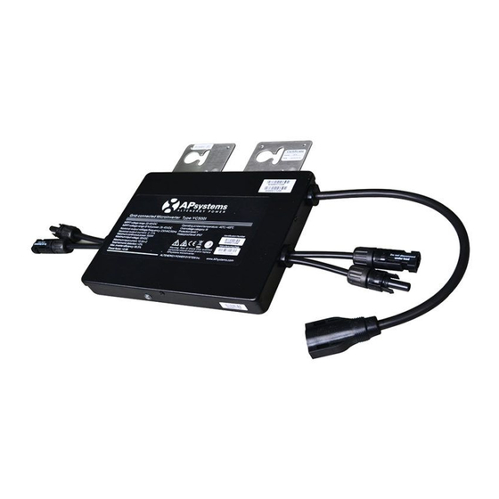
YC500I-EU Microinverter Quick Installation Guide
Step 1. Verify the grid voltage to match with microinverter rating
Step 2. Position the AC bus cable and install the AC branch circuit junction box
a. Install an appropriate junction box at a suitable location on the PV racking system.
b. Put one end of the AC bus cable into the branch junction box.
c. Place cable connecting to the point of utility interconnection into the branch junction box.
d. Wire the conductors
NOTE: Wiring colour code can be different according local regulation, check all the wires of the
installation before connecting to the AC bus to be sure they match.Wrong cabling can damage
irreparably the microinverters, such an issue is not covered by the warranty.
Step 3. Attach the APsystems Microinverters to the racking or the PV module frame
NOTE:Do not place the inverters (including DC and AC connectors) where exposed to the sun, rai
n or snow, even gap between modules. Allow a minimum of 3/4''(1.5cm.) between the roof and the
100mm
bottom of the Microinverter to allow proper air flow.
Attach to the racking
Option 1:
Option 2:
B
Attach to the PV module frame. Drill holes on the PV module frame before installing YC500I. Please check
with the module manufacturer the compatibilty of such installation process.
54
46
54
Connect the APsystems microinverter to AC bus cable
Step 4.
B
A
of the AC bus
: L - BROWN; N - BLUE; PE - YELLOW GREEN.
A
M8
Click
Best Practice:
Unlock Tool of AC Bus to split the
connectors.
1
2017.03.20 Rev1.3
M8
(not supplied by APsystems)
M4
Use the Bus Cable
Quick Installation Guide
Advertisement
Table of Contents

Related Manuals for APsystems YC500I-EU


Summary of Contents for APsystems YC500I-EU
- Page 1 Step 3. Attach the APsystems Microinverters to the racking or the PV module frame NOTE:Do not place the inverters (including DC and AC connectors) where exposed to the sun, rai n or snow, even gap between modules.
- Page 2 Complete the APsystems installation map Step 7. Each APsystems microinverter has two removable serial number labels. Peel labels off, affix one to the respective location on the APsystems installation map, and affix another to the PV module frame such that it is easily visible. Use the Scanning Gun to scan the serial numbers on the map into the computer or scan by mobile phone, then complete the setting (see ECU manual).
Need help?
Do you have a question about the YC500I-EU and is the answer not in the manual?
Questions and answers