Table of Contents
Advertisement
Quick Links
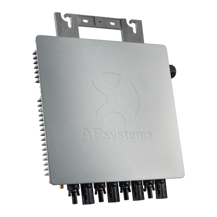
APsystems YC1000-3 3-Phase Microinverter
ALTENERGY POWER SYSTEM Inc.
latam.APsystems.com
APsystems Guadalajara:
AV. Lazaro Cardenas 2850-5º Piso, Colonia Jardines del Bosque
P. 44520, Guadalajara, Jalisco
TEL: 52 (33) -3188-4604
Installation / User Manual
EMAIL: info.latam@APsystems.com
(For Brazil)
Please scan the QR code
to get mobile app and
more support to help the
installation.
© All Rights Reserved
Advertisement
Table of Contents
Troubleshooting

Related Manuals for APsystems YC1000-3 3-Phase


Summary of Contents for APsystems YC1000-3 3-Phase
- Page 1 Installation / User Manual APsystems YC1000-3 3-Phase Microinverter (For Brazil) Please scan the QR code to get mobile app and more support to help the ALTENERGY POWER SYSTEM Inc. installation. latam.APsystems.com © All Rights Reserved APsystems Guadalajara: AV. Lazaro Cardenas 2850-5º Piso, Colonia Jardines del Bosque P.
-
Page 2: Table Of Contents
Required Parts and Tools from you......................8 Installation Procedures..........................9 Step 1 - Lay the AC bus according to the arrangement of APsystems Microinverter... 9 Step 2 - Attaching the APsystems Microinverters to the Racking........9 Step 3 - Connecting the APsystems Microinverter AC Cables to the AC bus cable... 10 Step 4 - Connecting APsystems Microinverters to the PV Module........11... -
Page 3: Important Safety Instructions
This manual contains important instructions to follow during installation and maintenance of the APsystems Photovoltaic Grid-connected Inverter (Microinverter). To reduce the risk of electrical shock and ensure the safe installation and operation of the APsystems Microinverter, the following symbols appear throughout this document to indicate dangerous conditions and important safety instructions. -
Page 4: Safety Instructions
Be aware that the body of the APsystems Microinverter is the heat sink and can reach a temperature of 80°C. To reduce risk of burns, do not touch the body of the Microinverter. Do NOT attempt to repair the APsystems Microinverter. If it fails, contact APsystems ... -
Page 5: Symbols Replace Words On The Equipment, On A Display
EMC and is authorized to energize, ground, and tag equipment, systems, and circuits in accordance with established safety procedures. The inverter and endues system may only be commissioned and operated by qualified personnel. APsystems YC1000-3 Installation/User Manual... -
Page 6: Apsystems Yc1000-3 System Introduction
APsystems YC1000-3 System Introduction The APsystems Microinverter is used in utility-interactive grid-tied applications, comprised of three key elements: APsystems Microinverter APsystems Energy Communication Unit (ECU) APsystems Energy Monitor and Analysis (EMA) web-based monitoring and analysis system Meter... - Page 7 The distributed microinverter system ensures that no single point of system failure exists across the PV system. APsystems microinverters are designed to operate at full power at ambient temperatures of up to +65°C (+149° F). The inverter housing is designed for outdoor installation and complies with the IP67 environmental enclosure rating.
-
Page 8: Apsystems Three-Phase Microinverter Yc1000-3
60, 72, 84 and 96 cell PV modules. For more information, please see the Technical Data page (p.18) of this manual, or sign in APsystems website to obtain a solar panel list which can match with APsystems Microinverters: www.APsystems.com... -
Page 9: Apsystems Microinverter System Installation
An AC GFCI device should not be used to protect the dedicated circuit Special Statement! to the APsystems microinverter even though it is an outside circuit. None of the small GFCI devices (5mA-30 mA) are designed for back feeding and will be damaged if back feed. In a... -
Page 10: Installation Procedures
Even if they are plugged into the solar array, they will not turn themselves on until they can read power from the grid. Do NOT connect APsystems Microinverters to the utility grid or energize the AC circuit until you have completed all of the installation procedures as described in the following sections. -
Page 11: Step 3 - Connecting The Apsystems Microinverter Ac Cables To The Ac Bus Cable
Installation Procedures Step 3 - Connecting the APsystems Microinverter AC Cables to the AC bus cable Click Figure 3 Cover all unused T connectors with Bus Cable T-CONN Cap to protect the T connectors. Figure 4 AC connector interface as follows, from left to right PE, N, L3, L2, L1. -
Page 12: Step 4 - Connecting Apsystems Microinverters To The Pv Module
Installation Procedures Step 4 - Connecting APsystems Microinverters to the PV Module Place the PV modules into position on the racking and connect the DC input cables to the microinverters based on optimum layout configuration (up to four PV modules per microinverter). -
Page 13: Step 6 - Installing The Ac Branch Circuit Junction Box
Double check to make sure all of the AC and DC wiring has been correctly installed. Ensure that none of the AC and/or DC wires are pinched or damaged. Make sure that all of the junction boxes are properly closed. APsystems YC1000-3 Installation/User Manual... -
Page 14: Step 7 - Completing The Apsystems Installation Map
Each APsystems microinverter has removable serial number labels. Peel labels off, and affix one to the respective location on the APsystems installation map, and affix another to the PV module frame which is easy to see.The warranty cards can be obtained from the appendix of this manual or APsystems website: www.APsystems.com... -
Page 15: Apsystems Microinverter System Operating Instructions
2. Turn ON the main utility-grid AC circuit breaker. Your system will start producing power after a five-minute safety delay period. 3. The APsystems Microinverters will start to send performance data over wireless to the ECU.The time required for all the microinverters in the system to report to the ECU will vary with the number of microinverters in the system. -
Page 16: Troubleshooting
Always disconnect AC power before disconnecting the PV module wires from the APsystems microinverter. The APsystems microinverter is powered by PV module DC power. Make sure you disconnect and reconnect the DC connections to watch for the three short LED flashes indicating start up. -
Page 17: Troubleshooting A Non-Operating Apsystems Microinverter
Verify the PV module DC voltage is within the allowable range shown in the Technical Data of this manual. If the problem persists, please call APsystems Technical Support. Do not attempt to repair the APsystems microinverter. If troubleshooting methods fail, please call APsystems Customer Support. APsystems YC1000-3 Installation/User Manual... -
Page 18: Replace A Microinverter
Follow the procedure to replace a failed APsystems Microinverter A. Remove the APsystems microinverter from the PV Module, in the following order: Disconnect the AC by turning off the branch circuit breaker. Cover the module with an opaque cover. -
Page 19: Technical Data
APsystems website www.APsystems.com. You must match the DC operating voltage range of the PV module with the allowable input voltage range of the APsystems Microinverter. The maximum open circuit voltage of the PV module must not exceed the specified maximum input voltage of the APsystems microinverter. -
Page 20: Yc1000-3 3-Phase Microinverter Datasheet
High Frequency Transformers, Galvanically Isolated Programmable through ECU in field to meet customer need. Depending on the local regulations. Specifications subject to change without notice - please ensure you are using the most recent update found at latam.APsystems.com © All Rights Reserved 2020/09/01 REV1.0... -
Page 21: Wiring Diagram
YELLOW GREEN PE 20 AMP CIRCUIT AC JUNCTION BOX BREAKER PER BRANCH CIRCUIT NEUTRAL BRANCH END CAP INSTALLED ON THE END OF AC BUS CABLE GROUND DISTRIBUTION PANEL 127V/220V THREE PHASE ENERGY COMMUNICATION UNIT Figure 10 APsystems YC1000-3 Installation/User Manual... -
Page 22: Sample Wiring Diagram - 220V/380V Three Phase
YELLOW GREEN PE 20 AMP CIRCUIT AC JUNCTION BOX BREAKER PER BRANCH CIRCUIT NEUTRAL BRANCH END CAP INSTALLED ON THE END OF AC BUS CABLE GROUND DISTRIBUTION PANEL 220V/380V THREE PHASE ENERGY COMMUNICATION UNIT Figure 11 APsystems YC1000-3 Installation/User Manual... -
Page 23: Yc1000-3 Accessory
7 AC Connector Female 、 Grid 2 Bus Cable End Cap 、 1 Bus Cable 、 3、 Bus Cable T CONN Cap 8 DC Extension Cable 、 4、 DC Male Connector Cap 5、 DC Female Connector Cap APsystems YC1000-3 Installation/User Manual... -
Page 24: Accessories Summary
DC Female Connector Cap(MC4) Cap(Optional) AC Connector (Male) 2300711032 25A AC Male Connector (EN,5-wire) (Optional) AC Connector (Female) 2300812032 25A AC Female Connector (EN,5-wire) (Optional) 2310310274 1m DC Extension Cable(MC4) DC Extension Cable (Optional) 2310360214 2m DC Extension Cable(MC4) APsystems YC1000-3 Installation/User Manual... - Page 25 The APsystems Installation Map is a diagram of the physical location of each microinverter in your PV installation. Each APsystems microinverter has a removable serial number label located on the mounting plate. Peel the label and affix it to the respective location on the APsystems installation map.
Need help?
Do you have a question about the YC1000-3 3-Phase and is the answer not in the manual?
Questions and answers