APsystems YC500-A Installation & User Manual
Photovoltaic grid-connected inverter
Hide thumbs
Also See for YC500-A:
- Installation and user manual (23 pages) ,
- Installation & user manual (29 pages)
Table of Contents
Advertisement
Quick Links
Advertisement
Table of Contents
Troubleshooting

Related Manuals for APsystems YC500-A


Summary of Contents for APsystems YC500-A
- Page 1 Installation/User Manual APsystems YC500-A Photovoltaic Grid-connected Inverter Version 4.2 11/15 APsystems 600 Ericksen Ave. NE Ste 200 Seattle, WA 98110 844-666-7035 : info@APsystems.com TEL: EMAIL www.APsystems.com WEB: © All Rights Reserved...
-
Page 2: Table Of Contents
Required parts and tools from installer Installation procedures Step 1 – Installing the AC Branch Circuit Junction Box Step 2 – Attaching the APsystems microinverters to the racking or the PV module frame Step 3 – Connecting the APsystems microinverter to the PV module Step 4 –... -
Page 3: Important Safety Instructions
APsystems microinverter system and the PV – array. ✔ Be aware that the body of the APsystems microinverter is the heat sink and can reach high temperatures. To reduce risk of burns, do not touch the body of the microinverter. -
Page 4: Radio Interference Statement
A) Relocate the receiving antenna and keep it well away from the equipment B) Consult the dealer or an experienced radio/TV technician for assistance. Changes or modifications not expressly approved by the party responsible for compliance may void the user’s authority to operate the equipment. APsystems YC500-A Installation/User Manual... -
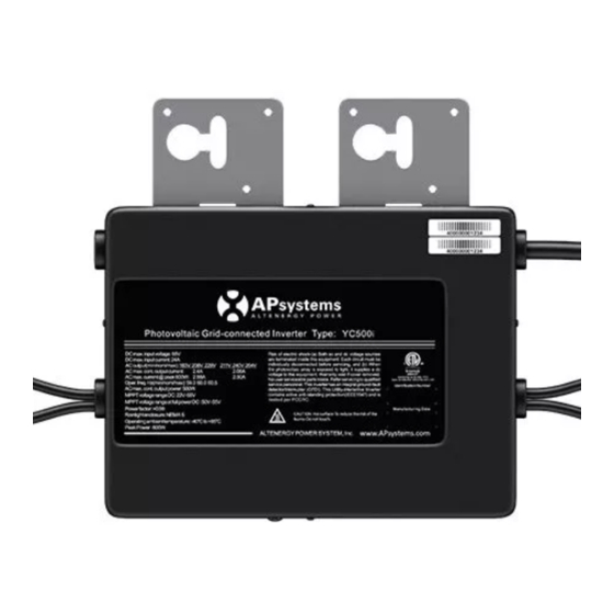
Page 5: Apsystems Yc500-A System Introduction
APsystems YC500-A System Introduction APsystems YC500 System Introduction The APsystems microinverter is used in utility-interactive grid-tied The APsystems Microinverter is used in utility-interactive grid-tied applications, and is comprised of three key elements: applications, comprised of three key elements: ✹ APsystems microinverter ... - Page 6 More reliable than centralized or string inverters The distributed APsystems microinverter system ensures that no single point of system failure exists across the PV–array. APsystems microinverters are designed to operate at full power at ambient outdoor temperatures of up to 149°F (65°C). The inverter housing is designed for outdoor installation and complies with the NEMA 6 environmental enclosure rating.
- Page 7 MC-4 Type or Customize Maximum units per branch of YC500 Max. parallel combination of APsystems modules = 7/branch for 20A breaker (14 PV modules) The APsystems YC500 has two independent DC inputs, each with independent MPPT control and data monitoring.
-
Page 8: Apsystems Microinverter System Installation
WARNING: Before installing or using an APsystems microinverter, please read all instructions and warnings in the technical documents and on the APsystems microinverter system itself as well as on the PV array. WARNING: Be aware that installation of this equipment includes the risk of electric shock. -
Page 9: Installation Procedures
APsystems microinverters are designed to only operate when they can sense power coming from the grid. Even if they are plugged into the PV array, they will not turn themselves on until they can read power from the grid. WARNING:... - Page 10 YC500 number per branch Installation Procedures EXTERNAL WIRE SIZE (AWG) MAXIMUM EXTERNAL CABLE LENGTH (ft) Step 2 - Attaching the APsystems Microinverters to the 370.7 237.1 167.9 124.3 93.6 70.2 51.4 35.7 Racking or the PV Module Frame 593.1 379.4 268.6...
-
Page 11: Step 3 - Connecting The Apsystems Microinverter To The Pv Module
Figure 9 Each APsystems Microinverter comes with a ground clamp that can accommodate a single #6 awg strand and #4 awg solid conductor. Check your local electrical code for grounding conductor sizing requirements. -
Page 12: Step 4 - Ground The System
PV module racking as described in Step 2, skip this step. Figure 7 Figure 9 Each APsystems Microinverter comes with a ground clamp that can accommodate a single #6 awg strand and #4 awg solid conductor. Check Each APsystems microinverter comes with a ground clamp that can your local electrical code for grounding conductor sizing requirements. -
Page 13: Step 5 - Connecting Apsystems Microinverters To The Ac Cables
Step 3 - Connecting the APsystems Microinverter AC Cables Installation Procedures Step 5 - Connecting the APsystems microinverter to the PV module Step 3 - Connecting the APsystems Microinverter AC Cables Figure 6 Best Practice: Use screwdriver to split the Main connectors. -
Page 14: Step 6 - Completing The Apsystems Installation Map
Each APsystems Microinverter has removable serial number labels. horizontal orientation to meet all field PV configurations. Peel labels off, affix one to the respective location on the APsystems Each APsystems microinverter has a removable serial number installation map, and fill in A,B in the label below(as Figure12) label. -
Page 15: Apsystems Microinverter System Operating Instructions
ECU and the inverters, the microinverters will start to send performance data over power line to the ECU. You can verify proper operation of the APsystems microinverters via the ECU. See the ECU Installation and Operation Manual for more information. -
Page 16: Troubleshooting
WARNING: Always disconnect AC power before disconnecting the PV module wires from the APsystems microinverter. Either disconnecting by the appropriate AC circuit breaker or unplugging the first AC connector of the first microinverter in a branch circuit is suitable as a ... -
Page 17: Troubleshooting A Non-Operating Apsystems Microinverter
WARNING: The APsystems microinverter is powered by PV module DC power. AFTER disconnecting the DC power, when reconnecting the PV modules to the microinverter, be sure to watch for the four short LED flashes - one red, and three green. - Page 18 PV module. Verify that the PV module DC voltage is within the allowable range shown in the Section 8 Technical Data of this manual. . If the problem persists, please call APsystems Customer Support at 844-666-7035. WARNING: Do not attempt to repair the APsystems microinverter.
-
Page 19: Replace A Microinverter
APsystems website for a list of approved PV modules. WARNING: You must match the DC operating voltage range of the PV module with the allowable input voltage range of the APsystems microinverter. WARNING: The maximum open circuit voltage of the PV module must not exceed the specified maximum input voltage of the APsystems microinverter. -
Page 20: Technical Data
APsystems YC500A/I Microinverter Datasheet Datasheet APsystems YC500A Microinverter Input Data (DC) Recommended PV Module Power (STC)Range 180W-310W MPPT Voltage Range 22V-45V Operation Voltage Range 16V-52V Maximum Input Voltage Startup Voltage Maximum Input Current 12A x 2 Output Data (AC) Nominal Output Voltage... - Page 21 ECU. Programmable through ECU to meet customer need. Depending on the local regulations. © All Rights Reserved 600 Ericksen Ave NE. Suite 200, Seattle, WA 98110 | 844.666.7035 | APsystems.com © All Rights Reserved APsystems YC500A/I Installation/User Manual...
-
Page 22: Efficency Curves
ALTENERGY POWER SYSTEM, INC. Efficency Curves ALTENERGY POWER SYSTEM, INC. 8. Efficiency Curves 8. Efficiency Curves YC500-NA Efficiency-temperature Curves YC500-A Efficency-temperature curves YC500-NA Efficiency-temperature Curves YC500-NA Efficiency Curves YC500-A Efficency curves YC500-NA Efficiency Curves APsystems YC500-A Installation/User Manual... -
Page 23: Wiring Diagrams
Wiring Diagram Sample Wiring Diagrams Sample Wiring Diagram - 120V/ 240V Split Phase Sample Wiring Diagram - 120V/240V Split Phase Figure 14 Figure 11 APsystems YC500A/I Installation/User Manual APsystems YC500-A Installation/User Manual... -
Page 24: Sample Wiring Diagram - 120V/ 208V Three Phase
Sample Wiring Diagram - 120V/ 208V Three Phase Sample wiring diagram - 120V/208V Three Phase Figure 12 Figure 15 NOTE: The ECU should function properly when connected to L1, L2 or L3. APsystems YC500A/I Installation/User Manual APsystems YC500-A Installation/User Manual...
Need help?
Do you have a question about the YC500-A and is the answer not in the manual?
Questions and answers