APsystems YC500I Installation & User Manual
Microinverter
Hide thumbs
Also See for YC500I:
- Installation & user manual (20 pages) ,
- Installation & user manual (29 pages)
Table of Contents
Advertisement
Quick Links
Installation / User Manual
Please scan the QR code to get
mobile app and more support
to help the installation.
ALTENERGY POWER SYSTEM Inc.
www.APsystems.com
APsystems Europe
Rue des Monts dor ZAC de Folliouses Sud-Les Echets 01700 Miribel, France
TEL: +33-481 65 60 40
© All Rights Reserved
EMAIL: emea@APsystems.com
I
YC500
Microinverter
Rev 1.4
(For Europe)
Advertisement
Table of Contents
Troubleshooting

Related Manuals for APsystems YC500I


Summary of Contents for APsystems YC500I
- Page 1 Please scan the QR code to get mobile app and more support to help the installation. ALTENERGY POWER SYSTEM Inc. www.APsystems.com APsystems Europe Rue des Monts dor ZAC de Folliouses Sud-Les Echets 01700 Miribel, France TEL: +33-481 65 60 40 EMAIL: emea@APsystems.com © All Rights Reserved...
-
Page 2: Table Of Contents
Step 1 - Position the AC bus cable........................ 9 Step 2 - Install the AC branch circuit junction box..................9 Step 3 - Attach the APsystems Microinverters to the racking or the PV module frame......9 Stpe 4 - Connect the APsystems microinverter to AC bus cable..............10 Step 5 - Install a Bus Cable End Cap at the end of AC bus cable.............. -
Page 3: Important Safety Instructions
APsystems Microinverter system and the solar-array. Be aware that the body of the APsystems Microinverter is the heat sink and can reach a temperature of 80°C. To reduce risk of burns, do not touch the body of the Microinverter. -
Page 4: Radio Interference Statement
ECU experiences loss of signal or data randomly, that is not a problem or a fault. If the ECU does not communicate with the EMA database at all, contact APsystems support. YC500I Installation/User Manual... -
Page 5: Symbols Replace Words On The Equipment, On A Display, Or In Manuals
EMC and is authorized to energize, ground, and tag equipment, systems, and circuits in accordance with established safety procedures. The inverter and endues system may only be commissioned and operated by qualified personnel. YC500I Installation/User Manual... -
Page 6: Apsystems Microinverter System Introduction
APsystems Microinverter System Introduction The APsystems Microinverter is used in utility-interactive grid-tied applications, comprised of three key elements: APsystems Microinverter APsystems Energy Communication Unit (ECU) APsystems Energy Monitor and Analysis (EMA) web-based monitoring and analysis system Module... - Page 7 More reliable than centralized or string inverters The distributed APsystems Microinverter system ensures that no single point of system failure exists across the PV system. APsystems Microin- verters are designed to operate at full power at ambient outdoor temper- atures of up to 149°F (65°C). The inverter housing is designed for outdoor installation and complies with the IP67 environmental enclosure rating.
-
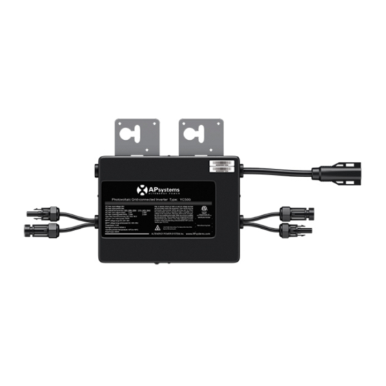
Page 8: Apsystems Microinverter Yc500I Introduction
APsystems Microinverter YC500I Introduction The APsystems YC500I Microinverters connect with the single-phase grid, and can also use multiple APsystems Microinverters in the form of single-phase grid to achieve three-phase grid, and operate with most 60 and 72 cell PV modules. For more information, please see the Technical Data page (p.18) of this manual. -
Page 9: Apsystems Microinverter System Installation
WARNING: When Local regulation requires to protect the microinverters with a 30mA Ground Default Protection ( GDP) device (The case in most European Countries), do not exceed 11 units of YC500I Microinverters by GDP device. WARNING: Perform all electrical installations in accordance with localelectrical codes. -
Page 10: Installation Procedures
Step 3 - Attach the APsystems Microinverters to the racking or the PV module frame a. Mark the location of the Microinverter on the rack, with respect to the PV module junction box or any other obstructions. -
Page 11: Stpe 4 - Connect The Apsystems Microinverter To Ac Bus Cable
Allow a minimum of 3/4’’(1.5cm.) between the roof and the bottom of the Microinverter to allow proper air flow. Stpe 4 - Connect the APsystems microinverter to AC bus cable Click Figure 5 Best Practice: Use the Bus Cable Unlock Tool of AC Bus to split the connectors. -
Page 12: Step 5 - Install A Bus Cable End Cap At The End Of Ac Bus Cable
Figure 8 Seal Body Step 6 - Connect APsystems Microinverters to the PV Modules Figure 9 NOTE: When plugging in the DC cables, the Microinverter should immediately blink one quick red and three short green. This will happen as soon as the cables are plugged in and will show that the Microinverter is functioning correctly. -
Page 13: Step 7 - Complete The Apsystems Installation Map
PV connections. a. Each APsystems Microinverter has removable serial number labels. Peel labels off, affix one to the respective location on the APsystems installation map, and fill in A,B in the label below (as figure12) according to the layout on the roof (as figure 11). Then affix another label to the PV module frame which is easy to see. -
Page 14: Step 8 - Place A Warning Notice
APsystems Microinverter&Energy Communication Unit Warranty Card The APsystems Installation Map is a diagram of the physical location of each microinverter in your PV installation. Each APsystems microinverter has a removable serial number label located on the mounting plate. Pee l the label and affix it to the respective location on the APsystems installation map. -
Page 15: Apsystems Microinverter System Operating Instructions
ECU. The time required for all the Microinverters in the system to report to the ECU will vary with the number of Microinverters in the system. You can verify proper operation of the APsystems Microinverters via the ECU. See the ECU Installation and Operation Manual for more information. -
Page 16: Troubleshooting
WARNING: Always disconnect AC power before disconnecting the PV module wires from the APsystems microinverter. Either disconnecting by the appropriate AC circuit breaker or unplugging the first AC connector of the first Microinverter in a branch circuit is suitable as a means of disconnection. -
Page 17: Troubleshooting A Non-Operating Apsystems Microinverter
6. Verify the PV module DC voltage is within the allowable range shown in the Technical Data of this manual. 7. If the problem persists, please call APsystems Customer Support. WARNING: Do not attempt to repair the APsystems microinverter. -
Page 18: Replace A Microinverter
Replace a microinverter Follow the procedure to replace a failed APsystems Microinverter A. Disconnect the APsystems Microinverter from the PV Module, in the order shown below: 1. Disconnect the AC by turning off the branch circuit breaker. 2. Disconnect the AC connector of the microinverter. -
Page 19: Technical Data
APsystems website www.APsystems.com. WARNING: You must match the DC operating voltage range of the PV module with the allowable input voltage range of the APsystems Microinverter. WARNING: The maximum open circuit voltage of the PV module... -
Page 20: Yc500I Microinverter Datasheet
YC500I Microinverter Datasheet France, Germany, Great Britain, Denmark, Sweden, Holland, Norway, Region Portugal,Ireland,etc. YC500I-EU, YC500I-UK, YC500I-FR, YC500i-VDE Model Input Data (DC) Recommended PV Module Power (STC)Range 180Wp-310Wp / 60 and 72-cell PV modules MPPT Voltage Range 22V-45V Operation Voltage Range... -
Page 21: Sample Wiring Diagram - Single Phase
Wiring Diagram Sample Wiring Diagram - Single Phase Figure 28 NOTE: Only for countries that using VDE 4105: each phase must be equipped with a NS protection and should not exceed maximum 3.68KVA. YC500I Installation/User Manual... - Page 22 The APsystems Installation Map is a diagram of the physical location of each microinverter in your PV installation. Each APsystems microinverter has a removable serial number label located on the mounting plate. Peel the label and affix it to the respective location on the APsystems installation map.
Need help?
Do you have a question about the YC500I and is the answer not in the manual?
Questions and answers