Table of Contents
Advertisement
Quick Links
ALTENERGY POWER SYSTEM Inc.
latam.APsystems.com
APsystems
APsystems Guadalajara:
AV. Lazaro Cardenas 2850-5º Piso, Colonia Jardines del Bosque
P. 44520, Guadalajara, Jalisco
TEL: 52 (33) -3188-4604 EMAIL: info.latam@APsystems.com
APsystems Microinverter
Installation manual
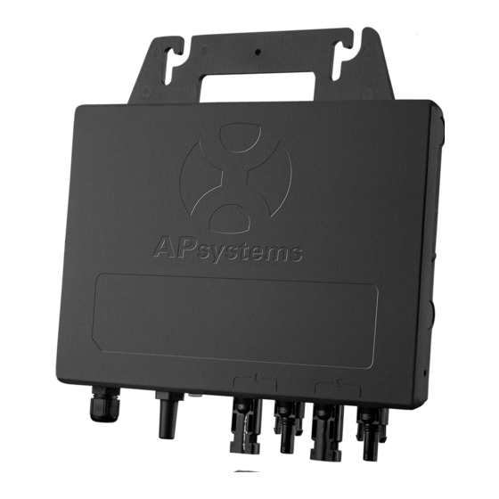
APsystems YC600B Microinverter
(For LATAM)
Please scan this QR code to
have access to our APPs and
Products information
© All Rights Reserved
Advertisement
Table of Contents
Troubleshooting

Related Manuals for APsystems YC600B


Summary of Contents for APsystems YC600B
- Page 1 Please scan this QR code to APsystems have access to our APPs and Products information APsystems Guadalajara: AV. Lazaro Cardenas 2850-5º Piso, Colonia Jardines del Bosque © All Rights Reserved P. 44520, Guadalajara, Jalisco TEL: 52 (33) -3188-4604 EMAIL: info.latam@APsystems.com...
-
Page 2: Table Of Contents
4.3.1 Step 1 - Verify the grid voltage to match with microinverter rating ........ 9 4.3.2 Step 2 - The AC bus distribution ..................... 9 4.3.3 Step 3 - Attach the APsystems Microinverters to the racking ........9 4.3.4 Step 4 - Ground the systems ....................10 4.3.5 Step 5 - Connect the APsystems microinverter to AC bus cable ......10... -
Page 3: Important Safety Instructions
APsystems Microinverter system and the solar-array. Be aware that the body of the APsystems Microinverter is the heat sink and can reach a temperature of 80°C. To reduce risk of burns, do not touch the body of the Microinverter. ... -
Page 4: Radio Interference Statement
A) Relocate the receiving antenna and keep it well away from the equipment. B) Consult the dealer or an experienced radio / TV technical for help. Changes or modifications not expressly approved by the party responsible for compliance may void the user’s authority to operate the equipment. APsystems YC600B Installation/User Manual... -
Page 5: Symbols Replace Words On The Equipment, On A Display, Or In Manuals
EMC and is authorized to energize, ground, and tag equipment, systems, and circuits in accordance with established safety procedures. The inverter and endues system may only be commissioned and operated by qualified personnel. APsystems YC600B Installation/User Manual... -
Page 6: Apsystems Microinverter System Introduction
2. APsystems Microinverter System Introduction The APsystems Microinverter is used in utility-interactive grid-tied applications, comprised of three key elements: APsystems Microinverter APsystems Energy Communication Unit (ECU) APsystems Energy Monitor and Analysis (EMA) web-based monitoring and analysis system... - Page 7 PV modules in the array. When PV modules in the array are affected by shade, dust, orientation, or any situation in which one module underperforms compared with the other units, the APsystems Microinverter ensures top performance from the array by maximizing the performance of each module within the array.
-
Page 8: Apsystems Microinverter Yc600B Introduction
Offering an unprecedented 375VA peak output power per channel, the YC600B works with 60 and 72-cell PV modules and offers dual, independent MPPT per panel. The YC600B also operates within a wider MPPT voltage range than competing brands for a greater energy harvest. -
Page 9: Apsystems Microinverter System Installation
Special Statement! An AC GFCI device should not be used to protect the dedicated circuit to the APsystems microinverter even though it is an outside circuit. None of the small GFCI devices (5mA-30 mA) are designed for back feeding and will be damaged if back feed. In a similar manner, AC AFCIs have not been evaluated for back feeding and may be damaged if back feed with the output of a PV inverter. -
Page 10: Installation Procedures
4.3.3 Step 3 - Attach the APsystems Microinverters to the racking a. Mark the location of the Microinverter on the rack, with respect to the PV module junction box or any other obstructions. -
Page 11: Step 4 - Ground The Systems
Figure 3 4.3.5 Step 5 - Connect the APsystems microinverter to AC bus cable Push the microinverter AC connector into the trunk cable connector until you hear a "click". Try to remove it to check that it is properly locked. -
Page 12: Step 6 - Install A Bus Cable End Cap At The End Of Ac Bus Cable
Figure 8 Body Seal 4.3.7 Step 7 - Connect APsystems Microinverters to the PV Modules Figure 9 When plugging in the DC cables, the microinverter should immediately blink green three times. This will happen as soon as the cables are plugged in and will show that the microinverter is functioning correctly. -
Page 13: Step 8 - Complete The Apsystems Installation Map
PV connections. a. Each APsystems Microinverter has removable serial number labels. b. Peel labels off, affix one to the respective location on the APsystems installation map, and fill in 1,2 in the label below,according to the layout on the roof. - Page 14 Peel the label and affix it to the respective location on the APsystems installation map. The APsystems Installation Map is a diagram of the physical location of each microinverter in your PV installation. Each APsystems microinverter has a removable serial number label located on the mounting plate. Pee l the label Installation Map Template and affix it to the respective location on the APsystems installation map.
-
Page 15: Apsystems Microinverter System Operating Instructions
Plug in the ECU and follow the instructions according to the manual for the ECU. The APsystems Microinverters will start to send performance data to the ECU. The time required for all the Microinverters in the system to report to the ECU will vary with the number of Microinverters in the system. -
Page 16: Troubleshooting
Always disconnect AC power before disconnecting the PV module wires from the APsystems Microinverter. The APsystems Microinverter is powered by PV module DC power. AFTER disconnecting the DC power, when reconnecting the PV modules to the Microinverter, be sure to watch for the three short LED flashes. -
Page 17: Troubleshooting A Non-Operating Apsystems Microinverter
Verify the PV module DC voltage is within the allowable range shown in the Technical Data of this manual. If the problem persists, please call APsystems Customer Support. Do not attempt to repair the APsystems microinverter. If troubleshooting methods fail, please return the microinverter to your distributor for replacement. 6.3 Maintenance No need to Maintenance. -
Page 18: Replace A Microinverter
7. Replace a microinverter Follow the procedure to replace a failed APsystems Microinverter A. Disconnect the APsystems Microinverter from the PV Module, in the order shown below: Disconnect the AC by turning off the branch circuit breaker. Disconnect the inverter AC connector from the AC Bus. -
Page 19: Technical Data
APsystems website www.APsystems.com. You must match the DC operating voltage range of the PV module with the allowable input voltage range of the APsystems Microinverter. The maximum open circuit voltage of the PV module must not exceed the specified maximum input voltage of the APsystems. -
Page 20: Yc600B Microinverter Datasheet
8.1 YC600B Microinverter Datasheet Region LATAM Input Data (DC) Recommended PV Module Power (STC) Range 300Wp-550Wp+ Peak Power Tracking Voltage 22-48V Operation Voltage Range 16-60V Maximum Input Voltage Maximum Input Current 12A x 2 Maximum Input Short Circuit Current 13.2A... - Page 21 (3) The inverter may enter to power de-grade mode under poor ventilation and heat dissipation installation environment. (4) Recommend no more than 80 inverters register to one ECU for stable communication. (5) To be eligible for the warranty, APsystems microinverters need to be monitored via the EMA portal. Please refer to our warranty T&Cs available on latam.APsystems.com.
-
Page 22: Wiring Diagram
SOLAR PANEL BROWN - L BLUE - N YELLOW GREEN - PE AC JUNCTION BOX Apsystems BUS CABLE END CAP YC600B INSTALL AT THE END OF AC BUS CABLE ENERGY COMMUNICATION UNIT DISTRIBUTION PANEL Figure 13 APsystems YC600B Installation/User Manual... - Page 23 APsystems Microinverter & Energy Communication Unit Installation Map The APsystems Installation Map is a diagram of the physical location of each microinverter in your PV installation. Each APsystems microinverter has two serial number labels. Peel the one label and affix it to the respective location on the APsystems installation map.
Need help?
Do you have a question about the YC600B and is the answer not in the manual?
Questions and answers