Table of Contents
Advertisement
Installation / User Manual
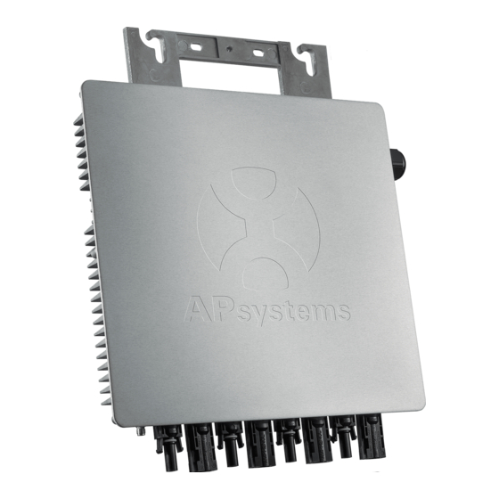
APsystems YC1000-3 3-Phase Microinverter
Rev 3.7
Please scan the QR code to get
mobile app and more support
to help the installation
ALTENERGY POWER SYSTEM Inc.
usa.APsystems.com
WEB:
APsystems America
600 Ericksen Ave NE, Suite 200 Seattle, WA 98110
TEL: 844-666-7035
EMAIL: info.usa@APsystems.com
(For North America)
© All Rights Reserved
Advertisement
Table of Contents
Troubleshooting

Related Manuals for APsystems YC1000-3-208


Summary of Contents for APsystems YC1000-3-208
- Page 1 Installation / User Manual APsystems YC1000-3 3-Phase Microinverter Rev 3.7 Please scan the QR code to get mobile app and more support to help the installation ALTENERGY POWER SYSTEM Inc. usa.APsystems.com WEB: APsystems America 600 Ericksen Ave NE, Suite 200 Seattle, WA 98110 TEL: 844-666-7035 EMAIL: info.usa@APsystems.com...
-
Page 2: Table Of Contents
PV Rapid Shut Down Equipment.......................... 8 Installation Procedures............................9 Step 1 - Lay the AC bus according to the arrangement of APsystems Microinverter........9 Step 2 - Attaching the APsystems Microinverters to the Racking..............9 Step 3 - Connecting the APsystems Microinverter Cables to the AC bus cable.........10 Step 4 - Connecting APsystems Microinverters to the PV Module............ -
Page 3: Important Safety Instructions
APsystems Photovoltaic Grid-connected Inverter (Microinverter). To reduce the risk of electrical shock and ensure the safe installation and operation of the APsystems Microinverter, the following symbols appear throughout this document to indicate dangerous conditions and important safety instructions. -
Page 4: Safety Instructions
APsystems Microinverter system and the solar-array. Be aware that the body of the APsystems Microinverter is the heat sink and can reach a temperature of 80°C. To reduce risk of burns, do not touch the body of the Microinverter. -
Page 5: Apsystems Yc1000-3 System Introduction
APsystems YC1000-3 System Introduction The APsystems Microinverter is used in utility-interactive grid-tied applications, comprised of three key elements: APsystems Microinverter APsystems Energy Communication Unit (ECU) APsystems Energy Monitor and Analysis (EMA) web-based monitoring and analysis system Meter... - Page 6 Ethernet or Wi-Fi connection to a broadband router. After installing and setting the ECU (see ECU manual), the full network of APsystems Microinverters automatically reports to the APsystems Energy Monitor and analysis (EMA) web server.
-
Page 7: Apsystems Three-Phase Microinverter Yc1000-3
APsystems Three-phase Microinverter YC1000-3 The APsystems YC1000-3 Microinverters connect with the Three-phase grid, and operate with most 60, 72, 84 and 96 cell PV modules. For more information, please see the Technical Data page (p.16) of this manual. Model Number... -
Page 8: Apsystems Microinverter System Installation
Installation MUST comply with local regulations and technical rules. Special Statement! An AC GFCI device should not be used to protect the dedicated circuit to the APsystems microinverter even though it is an outside circuit. None of the small GFCI devices (5mA-30 mA) are designed for back feeding and will be damaged if back feed. -
Page 9: Pv Rapid Shut Down Equipment
APsystems Microinverter System Installation PV Rapid Shut Down Equipment This product is PV Rapid Shut Down Equipment and conforms with NEC-2014 and NEC-2017 section 690.12, for AC and DC conductors, when installed according to the following requirements: Microinverters and all DC connections must be installed inside the array boundary. -
Page 10: Installation Procedures
Installation Procedures APsystems Microinverters are designed to only operate when they can sense power coming from the grid. Even if they are plugged into the solar array, they will not turn themselves on until they can read power from the grid. -
Page 11: Step 3 - Connecting The Apsystems Microinverter Cables To The Ac Bus Cable
Installation Procedures Step 3 - Connecting the APsystems Microinverter Cables to the AC bus cable. Click Figure 3 Cover all unused T connectors with Bus Cable T-CONN Cap to protect the T connectors. Figure 4 AC connector interface as follows, from left to right PE, N, L3, L2, L1. -
Page 12: Step 4 - Connecting Apsystems Microinverters To The Pv Module
Installation Procedures Step 4 - Connecting APsystems Microinverters to the PV Module. Place the PV modules into position on the racking and connect the DC input cables to the microinverters based on optimum layout configuration (up to four PV modules per microinverter). -
Page 13: Step 6 - Installing The Ac Branch Circuit Junction Box
Double check to make sure all of the AC and DC wiring WARNING: has been correctly installed. Ensure that none of the AC and/or DC wires are pinched or damaged. Make sure that all of the junction boxes are properly closed. APsystems YC1000-3 Installation/User Manual... -
Page 14: Step 7 - Completing The Apsystems Installation Map
APsystems website: www.APsystems.com b. Fill out the warranty cards and email to APsystems at support@APsystems.com. c. Register the system using your Installer Account on the APsystems EMA. You can then use the EMA website to view detailed performance of the PV system. - Page 15 ECU will vary with the number of microinverters in the system. You can verify proper operation of the APsystems microinverters via the ECU. See the ECU Installation and Operation Manual for more information.
-
Page 16: Troubleshooting
Always disconnect AC power before disconnecting WARNING: the PV module wires from the APsystems microinverter. The APsystems microinverter is powered by PV module WARNING: DC power. Make sure you disconnect and reconnect the DC connections to watch for the three short LED flashes indicating start up. -
Page 17: Troubleshooting A Non-Operating Apsystems Microinverter
5. Check the DC connections between the microinverter and the PV module. 6. Verify the PV module DC voltage is within the allowable range shown 7. If the problem persists, please call APsystems Technical Support. in the Technical Data of this manual. -
Page 18: Replace A Microinverter
Follow the procedure to replace a failed APsystems Microinverter. A. Remove the APsystems microinverter from the PV Module, in the following order: 1. Disconnect the AC by turning off the branch circuit breaker. 2. Cover the module with an opaque cover. -
Page 19: Technical Data
You must match the DC operating voltage range of WARNING: the PV module with the allowable input voltage range of the APsystems Microinverter. The maximum open circuit voltage of the PV module WARNING: must not exceed the specified maximum input voltage of the APsystems microinverter. YC1000-3 Installation/User Manual... -
Page 20: Yc1000-3-208 3-Phase Microinverter Datasheet
IEEE1547 Specifications subject to change without notice - please ensure you Programmable through ECU in field to meet customer need. are using the most recent update found at www.APsystems.com Depending on the local regulations. © All Rights Reserved YC1000-3 Installation/User Manual... -
Page 21: Yc1000-3-480 3-Phase Microinverter Datasheet
Programmable through ECU in field to meet customer need. Specifications subject to change without notice - please ensure you Depending on the local regulations. are using the most recent update found at www.APsystems.com © All Rights Reserved YC1000-3 Installation/User Manual... - Page 22 Note 1 Note 1: Utility Interconnection Voltage and Frequency Trip Limits and Trip Times Voltage and frequency limits for utility Interaction Maximum time (sec) (cycles) at Simulated utility source Condition 60 Hza before cessation of Voltage (V) Frequency (Hz) current to the simulated utility <...
-
Page 23: Wiring Diagram
Wiring Diagram Sample Wiring Diagram - 120V/ 208V Three Phase Figure 11 YC1000-3 Installation/User Manual... -
Page 24: Sample Wiring Diagram - 277V/ 480V Three Phase
Wiring Diagram Sample Wiring Diagram - 277V/ 480V Three Phase Figure 12 YC1000-3 Installation/User Manual... -
Page 25: Yc1000-3 Accessory
YC1000-3 Accessory Wiring Diagram 6 AC Connector Male 、 7 AC Connector Female 、 Grid 、 2 Bus Cable End Cap 1 Bus Cable 、 3、 Bus Cable T CONN Cap 8 DC Extension Cable 、 4、 DC Male Connector Cap 5、... -
Page 26: Accessories Summary
Accessories Summary Accessories Category Part NO. Name 2322302552 5-wire Bus Cable(14AWG,TC-ER,2m, BK-RD-BU-WT-GN) Bus Cable (Mandatory) 2322402552 5-wire Bus Cable(14AWG, TC-ER,4m, BK-RD-BU-WT-GN) Bus Cable End Cap 2062050005 5-wire Bus Cable End Cap (Mandatory) Bus Cable T-CONN Cap 2061252032 5-wire Bus Cable T-CONN Cap (Optional)... - Page 27 The APsystems Installation Map is a diagram of the physical location of each microinverter in your PV installation. Each APsystems microinverter has a removable serial number label located on the mounting plate. Peel the label and affix it to the respective location on the APsystems installation map.
Need help?
Do you have a question about the YC1000-3-208 and is the answer not in the manual?
Questions and answers